Enjoy the warmth you desire with TMP392 and STM32F415ZG
Your home, your comfort control
Published Nov 08, 2023
Click board™
Thermostat 4 Click
Dev. board
UNI Clicker
Compiler
NECTO Studio
MCU
STM32F415ZG
Embrace smarter living with our cutting-edge smart thermostat that optimizes energy usage while keeping you cozy.
A
A
Hardware Overview
How does it work?
Thermostat 4 Click is based on the TMP392, a resistor-programmable temperature switch from Texas Instruments that enable protection and detection of system thermal events from 30°C to 130°C. The device powers on when the supply voltage goes beyond 1.5V, and starts sampling the input resistance to set the two trip points and hysteresis value after power-on. Trip point for channel A can be set manually using onboard trimmer while trip point for channel B is set using TPL0501 digital potentiometer with 256 wiper positions used as as a two-terminal rheostat. With end-to-end resistance of 100 kΩ internal registers of the TPL0501 can be accessed using a SPI interface. The position of the wiper (W) terminal is controlled by the value in the 8-bit Wiper Resistance (WR) register. When the WR register contains all zeroes (zero-scale), the wiper terminal is closest to its L terminal. As the value of the WR register increases from all zeroes to all ones
(full-scale), the wiper moves from the position closest to the L terminal, to the position closest to the H terminal. At the same time, the resistance between W and L increases, whereas the resistance between W and H decreases. The relay is activated by the host MCU. The voltage for the coil activation is 5V, while the current through the coil is 40mA. The MCU is not able to drive the coil directly, therefore an N-chanel FET had to be added. Its gate is controlled by the host MCU, allowing the coil to drain enough current from the 5V mikroBUS™ power rail. A red color LED, labeled as ACTIVE is used to indicate that the transistor is in an open state and that the current is running through the relay coil. When the current through a coil (or any other inductor) is suddenly changed, the backEMF will be generated, opposing the changes of the current. This can sometimes lead to damage to the control circuit: in this case, the transistor will become inversely polarized. To
prevent this from happening, a flyback diode is added across the coil. During the normal operation, this diode does not conduct any current. However, when the coil is switched OFF, the inverse polarization will cause the current to pass through this diode with minimum resistance. This prevents inverse (flyback) voltage from building up, so the transistor remains safe. The Click board™ is equipped with all the necessary elements, required to provide a reliable operation: it has a varistor across the relay output contacts, preventing excessive voltage transients, it has a flyback diode for the backEMF generated within the relay coil, and a durable mechanical relay, that can withstand up to 20,000,000 mechanical cycles (no load connected). These features allow Thermostat 4 click to be used for a wide range of applications that have to be thermally controlled: various home appliances, air conditioners, cooling fans, small heaters, and more.

Features overview
Development board
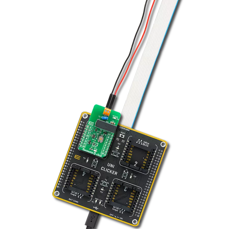
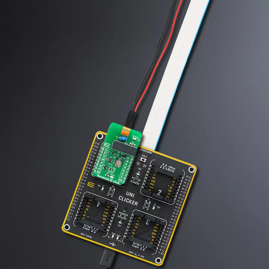
UNI Clicker is a compact development board designed as a complete solution that brings the flexibility of add-on Click boards™ to your favorite microcontroller, making it a perfect starter kit for implementing your ideas. It supports a wide range of microcontrollers, such as different ARM, PIC32, dsPIC, PIC, and AVR from various vendors like Microchip, ST, NXP, and TI (regardless of their number of pins), four mikroBUS™ sockets for Click board™ connectivity, a USB connector, LED indicators, buttons, a debugger/programmer connector, and two 26-pin headers for interfacing with external electronics. Thanks to innovative manufacturing technology, it allows you to build
gadgets with unique functionalities and features quickly. Each part of the UNI Clicker development kit contains the components necessary for the most efficient operation of the same board. In addition to the possibility of choosing the UNI Clicker programming method, using a third-party programmer or CODEGRIP/mikroProg connected to onboard JTAG/SWD header, the UNI Clicker board also includes a clean and regulated power supply module for the development kit. It provides two ways of board-powering; through the USB Type-C (USB-C) connector, where onboard voltage regulators provide the appropriate voltage levels to each component on the board, or using a Li-Po/Li
Ion battery via an onboard battery connector. All communication methods that mikroBUS™ itself supports are on this board (plus USB HOST/DEVICE), including the well-established mikroBUS™ socket, a standardized socket for the MCU card (SiBRAIN standard), and several user-configurable buttons and LED indicators. UNI Clicker is an integral part of the Mikroe ecosystem, allowing you to create a new application in minutes. Natively supported by Mikroe software tools, it covers many aspects of prototyping thanks to a considerable number of different Click boards™ (over a thousand boards), the number of which is growing every day.

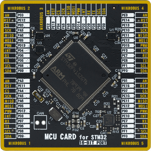
Microcontroller Overview
MCU Card / MCU
Type
8th Generation
Architecture
ARM Cortex-M4
MCU Memory (KB)
1024
Silicon Vendor
STMicroelectronics
Pin count
144
RAM (Bytes)
196608
Used MCU Pins
mikroBUS™ mapper
Take a closer look
Click board™ Schematic

Step by step
Project assembly

Start by selecting your development board and Click board™. Begin with the UNI Clicker as your development board.


Track your results in real time
Application Output
1. Application Output - In Debug mode, the 'Application Output' window enables real-time data monitoring, offering direct insight into execution results. Ensure proper data display by configuring the environment correctly using the provided tutorial.

2. UART Terminal - Use the UART Terminal to monitor data transmission via a USB to UART converter, allowing direct communication between the Click board™ and your development system. Configure the baud rate and other serial settings according to your project's requirements to ensure proper functionality. For step-by-step setup instructions, refer to the provided tutorial.

3. Plot Output - The Plot feature offers a powerful way to visualize real-time sensor data, enabling trend analysis, debugging, and comparison of multiple data points. To set it up correctly, follow the provided tutorial, which includes a step-by-step example of using the Plot feature to display Click board™ readings. To use the Plot feature in your code, use the function: plot(*insert_graph_name*, variable_name);. This is a general format, and it is up to the user to replace 'insert_graph_name' with the actual graph name and 'variable_name' with the parameter to be displayed.

Software Support
Library Description
This library contains API for Thermostat 4 Click driver.
Key functions:
thermostat4_hot_alert_state- This function read state from OA pin.thermostat4_relay_ctrl- This function write desired state on RLY pin.thermostat4_set_warm_hysteresis- This function write hysteresis data.
Open Source
Code example
The complete application code and a ready-to-use project are available through the NECTO Studio Package Manager for direct installation in the NECTO Studio. The application code can also be found on the MIKROE GitHub account.
/*!
 * @file
 * @brief Thermostat4 Click example
 *
 * # Description
 * Thermostat 4 Click reads alert on the warm and hot channel, using standard SPI communication.
 *
 * The demo application is composed of two sections :
 *
 * ## Application Init
 * Initializes Driver init, Relay test and
 * sets hysteresis on the WARM channel ( channel B ), after that starts uploading new data.
 *
 * ## Application Task
 * Reads Alert on the WARM and HOT channel.
 *
 * @note
 * The user has the option of adjusting the hysteresis for channel B via the SPI module
 * while for channel A it is adjusted via the potentiometer.
 *
 * @author MikroE Team
 *
 */

#include "board.h"
#include "log.h"
#include "thermostat4.h"

static thermostat4_t thermostat4;
static log_t logger;

void application_init ( void )
{
    log_cfg_t log_cfg;
    thermostat4_cfg_t thermostat4_cfg;

    /**
     * Logger initialization.
     * Default baud rate: 115200
     * Default log level: LOG_LEVEL_DEBUG
     * @note If USB_UART_RX and USB_UART_TX
     * are defined as HAL_PIN_NC, you will
     * need to define them manually for log to work.
     * See @b LOG_MAP_USB_UART macro definition for detailed explanation.
     */
    LOG_MAP_USB_UART( log_cfg );
    log_init( &logger, &log_cfg );
    log_info( &logger, " Application Init " );

    // Click initialization.
    thermostat4_cfg_setup( &thermostat4_cfg );
    THERMOSTAT4_MAP_MIKROBUS( thermostat4_cfg, MIKROBUS_1 );
    if ( SPI_MASTER_ERROR == thermostat4_init( &thermostat4, &thermostat4_cfg ) )
    {
        log_error( &logger, " Application Init Error. " );
        log_info( &logger, " Please, run program again... " );
        for ( ; ; );
    }

    log_printf( &logger, " RELAY ON\r\n" );
    thermostat4_relay_ctrl( &thermostat4, THERMOSTAT4_RELAY_ON );
    Delay_ms ( 1000 );
    log_printf( &logger, " RELAY OFF\r\n" );
    thermostat4_relay_ctrl( &thermostat4, THERMOSTAT4_RELAY_OFF );
    Delay_ms ( 500 );

    thermostat4_set_warm_hysteresis( &thermostat4, 0 );
    thermostat4_new_cfg_upload( &thermostat4 );

    log_info( &logger, " Application Task " );
}

void application_task ( void )
{
    if ( THERMOSTAT4_HOT_ALERT == thermostat4_hot_alert_state( &thermostat4 ) )
    {
        log_printf( &logger, " HOT ALERT\r\n" );
        thermostat4_relay_ctrl( &thermostat4, THERMOSTAT4_RELAY_ON );
    }
    else if ( THERMOSTAT4_WARM_ALERT == thermostat4_warm_alert_state( &thermostat4 ) )
    {
        log_printf( &logger, " WARM ALERT\r\n" );
        thermostat4_relay_ctrl( &thermostat4, THERMOSTAT4_RELAY_ON );
    }
    else
    {
        log_printf( &logger, " TEMPERATURE OK\r\n" );
        thermostat4_relay_ctrl( &thermostat4, THERMOSTAT4_RELAY_OFF );
    }
    Delay_ms ( 1000 );
    Delay_ms ( 1000 );
}

int main ( void )
{
    /* Do not remove this line or clock might not be set correctly. */
    #ifdef PREINIT_SUPPORTED
    preinit();
    #endif

    application_init( );

    for ( ; ; )
    {
        application_task( );
    }

    return 0;
}

// ------------------------------------------------------------------------ END
Additional Support
Resources
Category:Temperature & humidity


