Discover true colors with pinpoint chromatic accuracy using AS7263 and ATmega328P
Experience the brilliance of true whites
Published Feb 14, 2024
Click board™
Spectral 3 Click
Dev. board
Arduino UNO Rev3
Compiler
NECTO Studio
MCU
ATmega328P
Count on our multispectral light sensing solution for accurate, reliable, and real-time chromatic white color detection, ensuring the highest standards of color quality
A
A
Hardware Overview
How does it work?
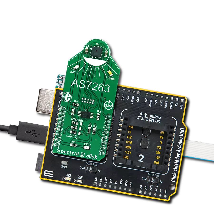
Spectral 3 Click is based on the AS7263, a 6 channel NIR Spectral_ID device with electronic shutter and smart Interface. This is a very advanced multispectral sensor, which incorporates a 6 photodiodes array element. Every photo element is filtered through the Gaussian filters, implemented through the nano-optic deposited interference filter technology, designed to provide ranges for 6 near-IR spectral channels: R = 610nm, S = 680nm, T = 730nm, U = 760nm, V = 810nm and W = 860nm, each with 20nm FWHM. The filter characteristics are tested and measured with the diffused white light. This technology ensures minimal drift of the readings and temperature stability. It should be noted that the filter accuracy will be affected by the angle of incidence, determined by an integrated aperture and the internal microlenses, which is ±20° for the AS7263. The measurements from the photo elements are digitized by the 16bit ADC converter and processed by the Spectral_ID engine. Besides the raw values of the six color elements, the engine calculates all the calibrated values available on this device and outputs them as 32bit float values. After the specified integration time (2.8ms min), those values are available in their respective registers and are accessible via the smart high-level UART interface driven by simple AT commands, or the I2C communication protocol bus. Even the temperature sensor can be accessed
via its register. A complete list of all the available color coordinates and the registers which hold these values can be found in the AS7263 datasheet. The sensor data is organized in two banks. The first bank contains readings from the S, T, U and V photodiodes, while the second bank contains readings from the R, T, U, and W photodiodes. Different modes allow readings to be made from each bank, as well as the combinations between these two banks. There is also a mode for one-shot reading when time-critical or triggered measurement needs to be made. The photodiode letter codes above, represent the channels of the respective wavelengths (Channel R, Channel S, Channel T, and more). An interrupt can be triggered when the data is ready to be read by the host, depending on the selected bank mode. If the interrupt is enabled (INT = 1), the INT line is pulled to a LOW logic level and DATA_RDY bit of the control register is set to 1. The INT line is released when the control register is read. The DATA_RDY bit will be cleared whenever the measurement registers are read. The interrupt will be generated after one or more integrating cycles are completed, depending on the selected bank mode. The INT line of the AS7263 is routed to the mikroBUS™ INT pin and can be used to trigger an interrupt on the host MCU. More about bank reading modes and the interrupts can be found in the provided AS7263 datasheet. The RESET line of
the sensor is routed to the mikroBUS™ RST pin. If this line is pulled to a LOW level for more than 100ms, it will reset the device. The sensor firmware is kept externally, on the auxiliary flash memory IC. The AT25SF041, an SPI serial flash memory is used for storing the firmware of the AS7263 sensor. The AT25SF041 IC communicates with the sensor via the SPI lines, internally routed on the Spectral 3 click. UART and I2C lines of the AS7263 sensor are routed to the mikroBUS™ respective UART pins (RX/TX and SDA/SCL). To select which interface will be used to drive the sensor IC, three onboard SMD jumpers labeled as COM SEL need to be moved either to the left position (to enable UART), or to the right position (to enable I2C). It should be noted that all the SMD jumpers need to be moved at once - if some of them are set as UART and some as I2C, the communication might not be possible at all. There are two integrated programmable LED drivers on the AS7263 sensor. The first LED constant current driver can be programmed up to 10mA and it can be used as the status indicator. It is also activated during the sensor firmware programming. The second LED driver is intended for driving of the light source for the measurement surface illumination. It can drive high brightness LED with up to 100mA. Both of these LED drivers are available through the communication interfaces.

Features overview
Development board
Arduino UNO is a versatile microcontroller board built around the ATmega328P chip. It offers extensive connectivity options for various projects, featuring 14 digital input/output pins, six of which are PWM-capable, along with six analog inputs. Its core components include a 16MHz ceramic resonator, a USB connection, a power jack, an
ICSP header, and a reset button, providing everything necessary to power and program the board. The Uno is ready to go, whether connected to a computer via USB or powered by an AC-to-DC adapter or battery. As the first USB Arduino board, it serves as the benchmark for the Arduino platform, with "Uno" symbolizing its status as the
first in a series. This name choice, meaning "one" in Italian, commemorates the launch of Arduino Software (IDE) 1.0. Initially introduced alongside version 1.0 of the Arduino Software (IDE), the Uno has since become the foundational model for subsequent Arduino releases, embodying the platform's evolution.

Microcontroller Overview
MCU Card / MCU

Architecture
AVR
MCU Memory (KB)
32
Silicon Vendor
Microchip
Pin count
28
RAM (Bytes)
2048
You complete me!
Accessories
Click Shield for Arduino UNO has two proprietary mikroBUS™ sockets, allowing all the Click board™ devices to be interfaced with the Arduino UNO board without effort. The Arduino Uno, a microcontroller board based on the ATmega328P, provides an affordable and flexible way for users to try out new concepts and build prototypes with the ATmega328P microcontroller from various combinations of performance, power consumption, and features. The Arduino Uno has 14 digital input/output pins (of which six can be used as PWM outputs), six analog inputs, a 16 MHz ceramic resonator (CSTCE16M0V53-R0), a USB connection, a power jack, an ICSP header, and reset button. Most of the ATmega328P microcontroller pins are brought to the IO pins on the left and right edge of the board, which are then connected to two existing mikroBUS™ sockets. This Click Shield also has several switches that perform functions such as selecting the logic levels of analog signals on mikroBUS™ sockets and selecting logic voltage levels of the mikroBUS™ sockets themselves. Besides, the user is offered the possibility of using any Click board™ with the help of existing bidirectional level-shifting voltage translators, regardless of whether the Click board™ operates at a 3.3V or 5V logic voltage level. Once you connect the Arduino UNO board with our Click Shield for Arduino UNO, you can access hundreds of Click boards™, working with 3.3V or 5V logic voltage levels.

Used MCU Pins
mikroBUS™ mapper
Take a closer look
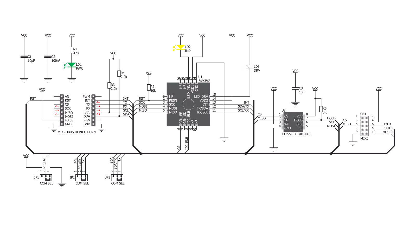
Click board™ Schematic
Step by step
Project assembly

Start by selecting your development board and Click board™. Begin with the Arduino UNO Rev3 as your development board.


Software Support
Library Description
This library contains API for Spectral 3 Click driver.
Key functions:
spectral3_module_reset- Reset modulespectral3_send_command- Send commandspectral3_get_data- Read raw X, Y, Z and NIR data as well as two special internal registers D, & C.
Open Source
Code example
The complete application code and a ready-to-use project are available through the NECTO Studio Package Manager for direct installation in the NECTO Studio. The application code can also be found on the MIKROE GitHub account.
/*!
 * \file
 * \brief Spectral3 Click example
 *
 * # Description
 * This example reads and processes data from Spectral 3 Clicks.
 *
 * The demo application is composed of two sections :
 *
 * ## Application Init
 * Initializes the driver and configures the sensor.
 *
 * ## Application Task
 * Reads the values of all 6 channels and parses it to the USB UART each second.
 *
 * ## Additional Function
 * - spectral3_process ( ) - The general process of collecting the sensor responses.
 *
 * \author MikroE Team
 *
 */
// ------------------------------------------------------------------- INCLUDES

#include "board.h"
#include "log.h"
#include "spectral3.h"
#include "string.h"

#define PROCESS_COUNTER 10
#define PROCESS_RX_BUFFER_SIZE 200
#define PROCESS_PARSER_BUFFER_SIZE 400

#define SPECTRAL3_CMD_DATA      "ATDATA"
#define SPECTRAL3_CMD_AT        "AT"
#define SPECTRAL3_CMD_GAIN      "ATGAIN=2"
#define SPECTRAL3_CMD_MODE      "ATTCSMD=2"

// ------------------------------------------------------------------ VARIABLES

static spectral3_t spectral3;
static log_t logger;

static char current_parser_buf[ PROCESS_PARSER_BUFFER_SIZE ];

// ------------------------------------------------------- ADDITIONAL FUNCTIONS

static void spectral3_process ( void )
{
    int32_t rsp_size;
    uint16_t rsp_cnt = 0;

    char uart_rx_buffer[ PROCESS_RX_BUFFER_SIZE ] = { 0 };
    uint8_t check_buf_cnt;
    uint8_t process_cnt = PROCESS_COUNTER;

    // Clear parser buffer
    memset( current_parser_buf, 0 , PROCESS_PARSER_BUFFER_SIZE );

    while( process_cnt != 0 )
    {
        rsp_size = spectral3_generic_read( &spectral3, &uart_rx_buffer, PROCESS_RX_BUFFER_SIZE );

        if ( rsp_size > 0 )
        {
            // Validation of the received data
            for ( check_buf_cnt = 0; check_buf_cnt < rsp_size; check_buf_cnt++ )
            {
                if ( uart_rx_buffer[ check_buf_cnt ] == 0 )
                {
                    uart_rx_buffer[ check_buf_cnt ] = 13;
                }
            }

            // Storages data in parser buffer
            rsp_cnt += rsp_size;
            if ( rsp_cnt < PROCESS_PARSER_BUFFER_SIZE )
            {
                strncat( current_parser_buf, uart_rx_buffer, rsp_size );
            }

            // Clear RX buffer
            memset( uart_rx_buffer, 0, PROCESS_RX_BUFFER_SIZE );
        }
        else
        {
            process_cnt--;

            // Process delay
            Delay_100ms( );
        }
    }
}

static void parser_application ( )
{
    uint16_t read_data[ 6 ];

    spectral3_send_command( &spectral3, SPECTRAL3_CMD_DATA );
    spectral3_process( );

    spectral3_get_data( current_parser_buf, read_data );

    log_printf( &logger, "-- R value: %d \r\n", read_data[ 0 ] );
    log_printf( &logger, "-- S value: %d \r\n", read_data[ 1 ] );
    log_printf( &logger, "-- T value: %d \r\n", read_data[ 2 ] );
    log_printf( &logger, "-- U value: %d \r\n", read_data[ 3 ] );
    log_printf( &logger, "-- V value: %d \r\n", read_data[ 4 ] );
    log_printf( &logger, "-- W value: %d \r\n", read_data[ 5 ] );
    log_printf( &logger, "-----------------\r\n" );
}

// ------------------------------------------------------ APPLICATION FUNCTIONS

void application_init ( void )
{
    log_cfg_t log_cfg;
    spectral3_cfg_t cfg;

    /**
     * Logger initialization.
     * Default baud rate: 115200
     * Default log level: LOG_LEVEL_DEBUG
     * @note If USB_UART_RX and USB_UART_TX
     * are defined as HAL_PIN_NC, you will
     * need to define them manually for log to work.
     * See @b LOG_MAP_USB_UART macro definition for detailed explanation.
     */
    LOG_MAP_USB_UART( log_cfg );
    log_init( &logger, &log_cfg );
    log_info( &logger, "---- Application Init ----" );

    //  Click initialization.

    spectral3_cfg_setup( &cfg );
    SPECTRAL3_MAP_MIKROBUS( cfg, MIKROBUS_1 );
    spectral3_init( &spectral3, &cfg );

    spectral3_module_reset( &spectral3 );
    Delay_ms ( 500 );

    log_printf( &logger, "Configuring the sensor...\r\n" );
    spectral3_send_command( &spectral3, SPECTRAL3_CMD_AT );
    spectral3_process( );
    spectral3_send_command( &spectral3, SPECTRAL3_CMD_GAIN );
    spectral3_process( );
    spectral3_send_command( &spectral3, SPECTRAL3_CMD_MODE );
    spectral3_process( );
    log_printf( &logger, "The sensor has been configured!\r\n" );
    Delay_ms ( 1000 );
}

void application_task ( void )
{
    parser_application( );
}

int main ( void )
{
    /* Do not remove this line or clock might not be set correctly. */
    #ifdef PREINIT_SUPPORTED
    preinit();
    #endif

    application_init( );

    for ( ; ; )
    {
        application_task( );
    }

    return 0;
}

// ------------------------------------------------------------------------ END
Additional Support
Resources
Category:Optical


