Provide superior illumination with CAT3224 and STM32F031K6
Your beacon of light in the dark
Published Oct 01, 2024
Click board™
LED Flash Click
Dev. board
Nucleo 32 with STM32F031K6 MCU
Compiler
NECTO Studio
MCU
STM32F031K6
With a focus on innovation and illumination, our purpose is to empower individuals with a cutting-edge LED flashlight solution that ensures longer-lasting and brighter light when you need it most
A
A
Hardware Overview
How does it work?
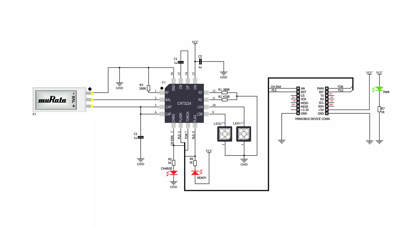
LED Flash Click is based on the CAT3224, a flash LED driver from ON Semiconductor. The click is designed to run on a 5V power supply. It communicates with the target microcontroller over the following pins on the mikroBUS™ line: AN, RST, PWM, and INT. The CAT3224 is a very high−current integrated flash LED driver which also supports the charging function for a dual−cell supercapacitor applications. Ideal for Li−ion battery−powered systems, it delivers up to 4A LED flash pulses, far beyond the peak current capability of the battery. Dual−mode 1x/2x charge pump charges the stacked supercapacitor to a nominal voltage of 5.4 V, while an active balance control circuit ensures that both capacitor cell voltages remain matched. The driver also features two matched current sources. External resistors
provide the adjustment for the maximum flash mode current (up to 4 A) and the torch mode current (up to 400 mA). A built−in safety timer automatically terminates the flash pulse beyond a maximum duration of 300 ms. The CAT3224 has a shutdown mode that is so low that ON Semiconductor can safely call it "zero" mode. In this mode, it typically uses only 1μA. On the LED Flash click there are three different LED indicators, here is how they operate: CHARGE — When this LED is on the driver is in charge mode; READY — When this LED is on it indicates that the supercapacitor is fully charged; PWR — Indicates if power is present. FLAG is an active−low open−drain output that notifies the microcontroller that the supercapacitor is fully charged by pulling the output low (pin 15 in the
mikroBUS). When using FLAG, this pin should be connected to a positive rail via an external pull−up resistor. TORCH is the torch mode enable pin. When high, the LED current sources are enabled in torch mode. FLASH is the flash mode enable pin. When high, the LED current sources are enabled in flash mode. If FLASH is kept high for longer than 300 ms typical, the LED channels are automatically disabled. LEDA, LEDB are connected internally to the current sources and must be connected to the LED anodes. Each output is independently current regulated. These pins enter a high−impedance ‘zero’ current state whenever the device is placed in shutdown mode or FLASH and TORCH are low.


Features overview
Development board
Nucleo 32 with STM32F031K6 MCU board provides an affordable and flexible platform for experimenting with STM32 microcontrollers in 32-pin packages. Featuring Arduino™ Nano connectivity, it allows easy expansion with specialized shields, while being mbed-enabled for seamless integration with online resources. The
board includes an on-board ST-LINK/V2-1 debugger/programmer, supporting USB reenumeration with three interfaces: Virtual Com port, mass storage, and debug port. It offers a flexible power supply through either USB VBUS or an external source. Additionally, it includes three LEDs (LD1 for USB communication, LD2 for power,
and LD3 as a user LED) and a reset push button. The STM32 Nucleo-32 board is supported by various Integrated Development Environments (IDEs) such as IAR™, Keil®, and GCC-based IDEs like AC6 SW4STM32, making it a versatile tool for developers.

Microcontroller Overview
MCU Card / MCU

Architecture
ARM Cortex-M0
MCU Memory (KB)
32
Silicon Vendor
STMicroelectronics
Pin count
32
RAM (Bytes)
4096
You complete me!
Accessories
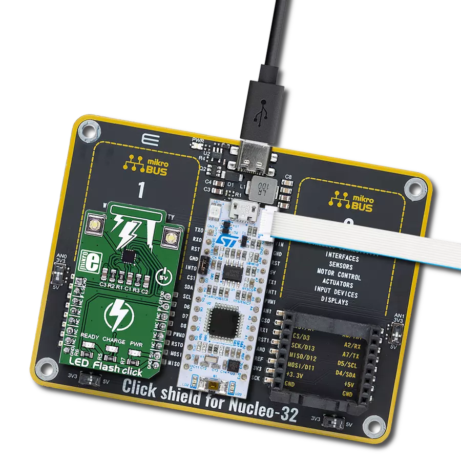
Click Shield for Nucleo-32 is the perfect way to expand your development board's functionalities with STM32 Nucleo-32 pinout. The Click Shield for Nucleo-32 provides two mikroBUS™ sockets to add any functionality from our ever-growing range of Click boards™. We are fully stocked with everything, from sensors and WiFi transceivers to motor control and audio amplifiers. The Click Shield for Nucleo-32 is compatible with the STM32 Nucleo-32 board, providing an affordable and flexible way for users to try out new ideas and quickly create prototypes with any STM32 microcontrollers, choosing from the various combinations of performance, power consumption, and features. The STM32 Nucleo-32 boards do not require any separate probe as they integrate the ST-LINK/V2-1 debugger/programmer and come with the STM32 comprehensive software HAL library and various packaged software examples. This development platform provides users with an effortless and common way to combine the STM32 Nucleo-32 footprint compatible board with their favorite Click boards™ in their upcoming projects.

Used MCU Pins
mikroBUS™ mapper
Take a closer look
Click board™ Schematic
Step by step
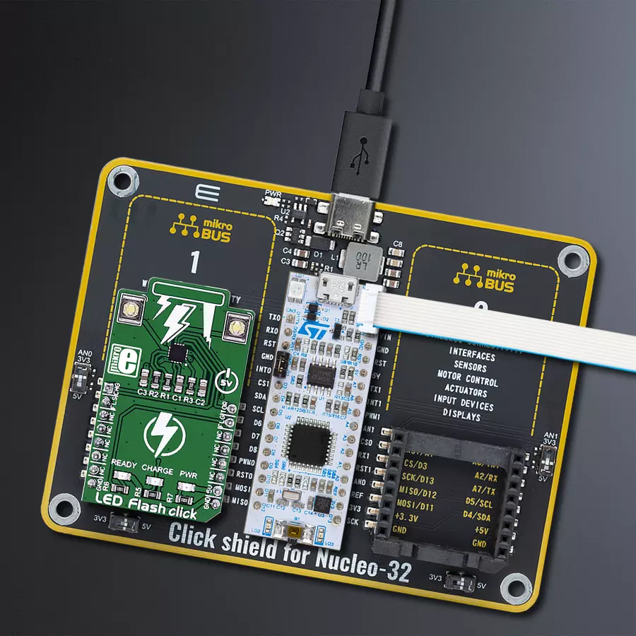
Project assembly

Start by selecting your development board and Click board™. Begin with the Nucleo 32 with STM32F031K6 MCU as your development board.


Track your results in real time
Application Output
1. Application Output - In Debug mode, the 'Application Output' window enables real-time data monitoring, offering direct insight into execution results. Ensure proper data display by configuring the environment correctly using the provided tutorial.

2. UART Terminal - Use the UART Terminal to monitor data transmission via a USB to UART converter, allowing direct communication between the Click board™ and your development system. Configure the baud rate and other serial settings according to your project's requirements to ensure proper functionality. For step-by-step setup instructions, refer to the provided tutorial.

3. Plot Output - The Plot feature offers a powerful way to visualize real-time sensor data, enabling trend analysis, debugging, and comparison of multiple data points. To set it up correctly, follow the provided tutorial, which includes a step-by-step example of using the Plot feature to display Click board™ readings. To use the Plot feature in your code, use the function: plot(*insert_graph_name*, variable_name);. This is a general format, and it is up to the user to replace 'insert_graph_name' with the actual graph name and 'variable_name' with the parameter to be displayed.

Software Support
Library Description
This library contains API for LED Flash Click driver.
Key functions:
ledflash_char_supcap_enable- Charge Supercapacitor Enable functionledflash_flash_enable- Flash Enable functionledflash_flash_rdy_flag- Check Flash Ready Flag function
Open Source
Code example
The complete application code and a ready-to-use project are available through the NECTO Studio Package Manager for direct installation in the NECTO Studio. The application code can also be found on the MIKROE GitHub account.
/*!
 * \file
 * \brief LED Flash Click example
 *
 * # Description
 * This application switching on and off led flash.
 *
 * The demo application is composed of two sections :
 *
 * ## Application Init
 * Initialization driver enables GPIO, starts write log and issues a warning.
 *
 * ## Application Task
 * This example demonstrates the use of LED Flash Click board by flashing
 * with LEDs when ever supercapacitor is at a full voltage.
 *
 * \author MikroE Team
 *
 */
// ------------------------------------------------------------------- INCLUDES

#include "board.h"
#include "log.h"
#include "ledflash.h"

// ------------------------------------------------------------------ VARIABLES

static ledflash_t ledflash;
static log_t logger;

// ------------------------------------------------------ APPLICATION FUNCTIONS

void application_init ( void )
{
    log_cfg_t log_cfg;
    ledflash_cfg_t cfg;

    /**
     * Logger initialization.
     * Default baud rate: 115200
     * Default log level: LOG_LEVEL_DEBUG
     * @note If USB_UART_RX and USB_UART_TX
     * are defined as HAL_PIN_NC, you will
     * need to define them manually for log to work.
     * See @b LOG_MAP_USB_UART macro definition for detailed explanation.
     */
    LOG_MAP_USB_UART( log_cfg );
    log_init( &logger, &log_cfg );
    log_info( &logger, "---- Application Init ----" );

    //  Click initialization.

    ledflash_cfg_setup( &cfg );
    LEDFLASH_MAP_MIKROBUS( cfg, MIKROBUS_1 );
    ledflash_init( &ledflash, &cfg );
    Delay_ms ( 100 );

    log_printf( &logger, "----------------------------------\r\n" );
    log_printf( &logger, " LED Flash Click \r\n" );
    log_printf( &logger, "----------------------------------\r\n" );
    log_printf( &logger, "/////////////////\r\n" );
    log_printf( &logger, " WARNING!!! \r\n" );
    log_printf( &logger, " DO NOT LOOK \r\n" );
    log_printf( &logger, " INTO THE LEDS, \r\n" );
    log_printf( &logger, " WHILE THAY ARE ON!!! \r\n" );
    log_printf( &logger, "/////////////////\r\n" );
    Delay_ms ( 1000 );
}

void application_task (  )
{
    uint8_t state;

    log_printf( &logger, " Charge Supercapacitor Enable \r\n" );
    ledflash_char_supcap_enable( &ledflash );
    Delay_ms ( 1000 );
    state = ledflash_flash_rdy_flag( &ledflash );

    if ( state == 0 )
    {
        log_printf( &logger, " Flash ON! \r\n" );
        ledflash_flash_enable( &ledflash );
    }
    else
    {
        log_printf( &logger, " Flash OFF! \r\n" );
        ledflash_flash_disable( &ledflash );
    }
    log_printf( &logger, "----------------------------------\r\n" );
}

int main ( void )
{
    /* Do not remove this line or clock might not be set correctly. */
    #ifdef PREINIT_SUPPORTED
    preinit();
    #endif

    application_init( );

    for ( ; ; )
    {
        application_task( );
    }

    return 0;
}

// ------------------------------------------------------------------------ END


