使用 DS1307 和 STM32F302VC 提供高精度实时时钟和日历功能
电池备份的实时时钟解决方案,确保持续跟踪
已发布 7月 22, 2025
点击板
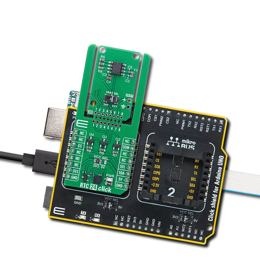
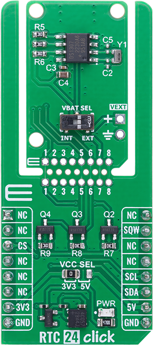
RTC 24 Click
开发板
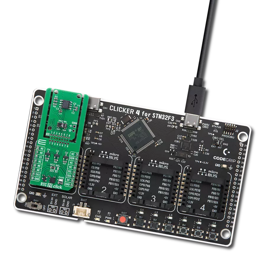
CLICKER 4 for STM32F302VCT6
编译器
NECTO Studio
微控制器单元
STM32F302VC
通过强大的实时时钟功能,确保数据记录器和计量系统始终保持精准时间戳
A
A
硬件概览
它是如何工作的?
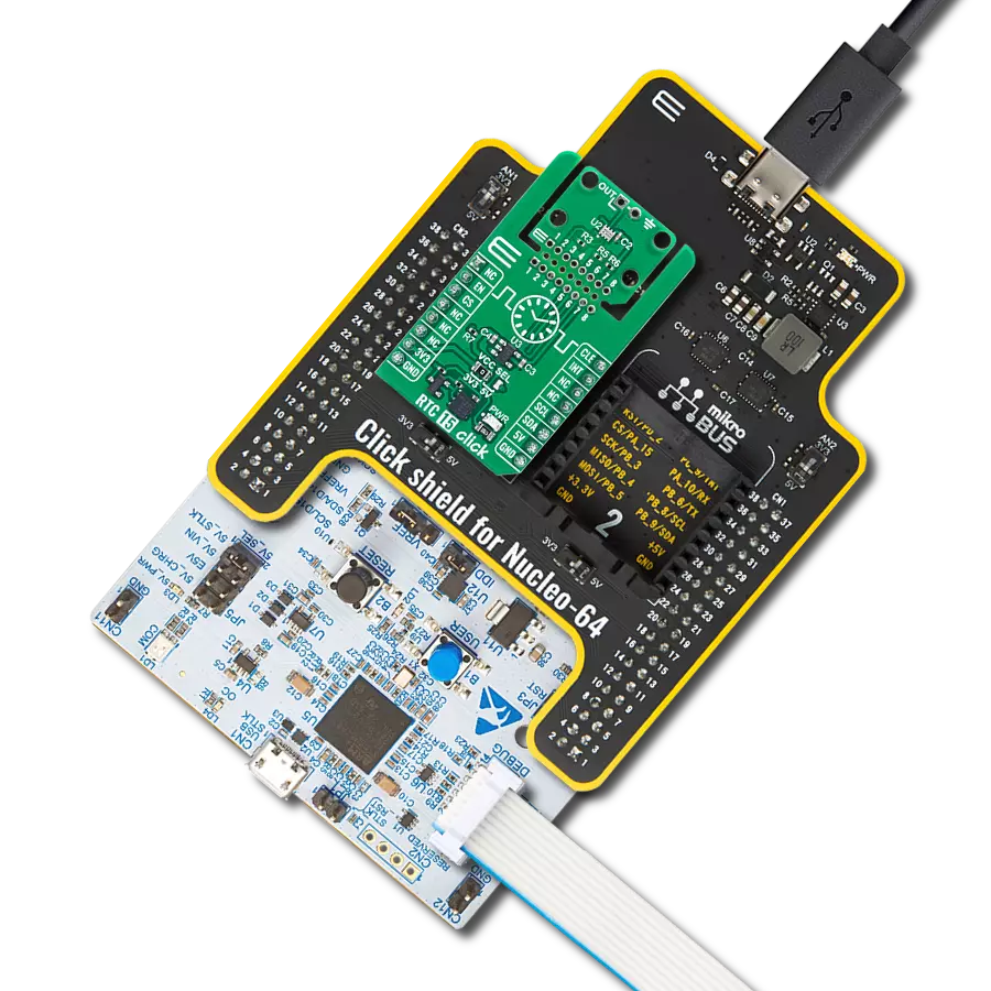
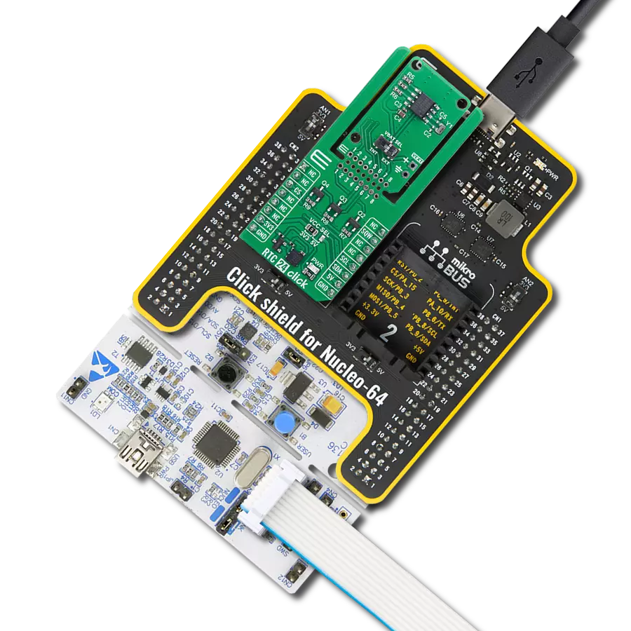
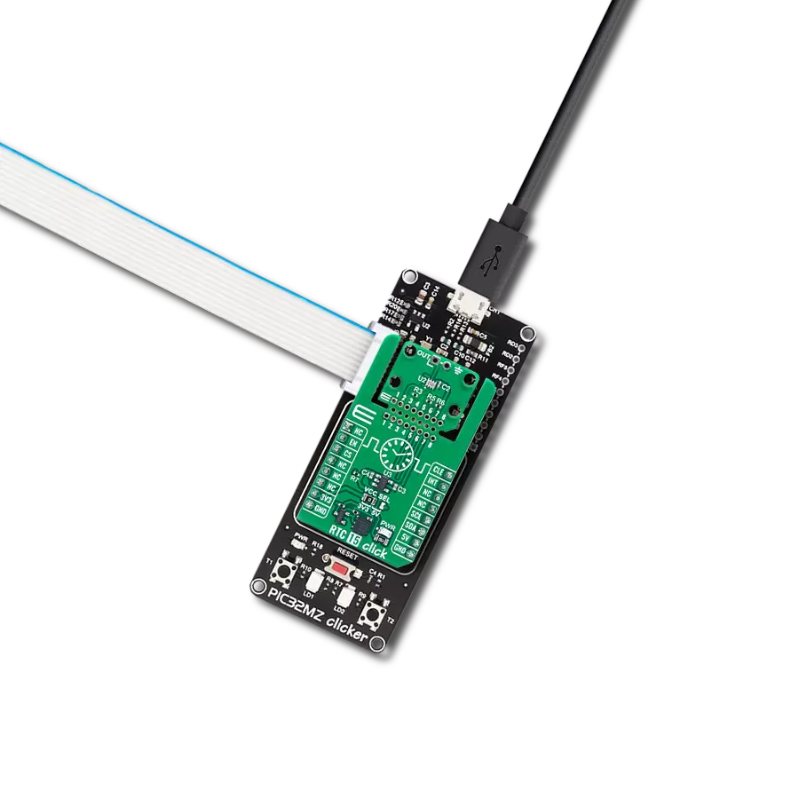
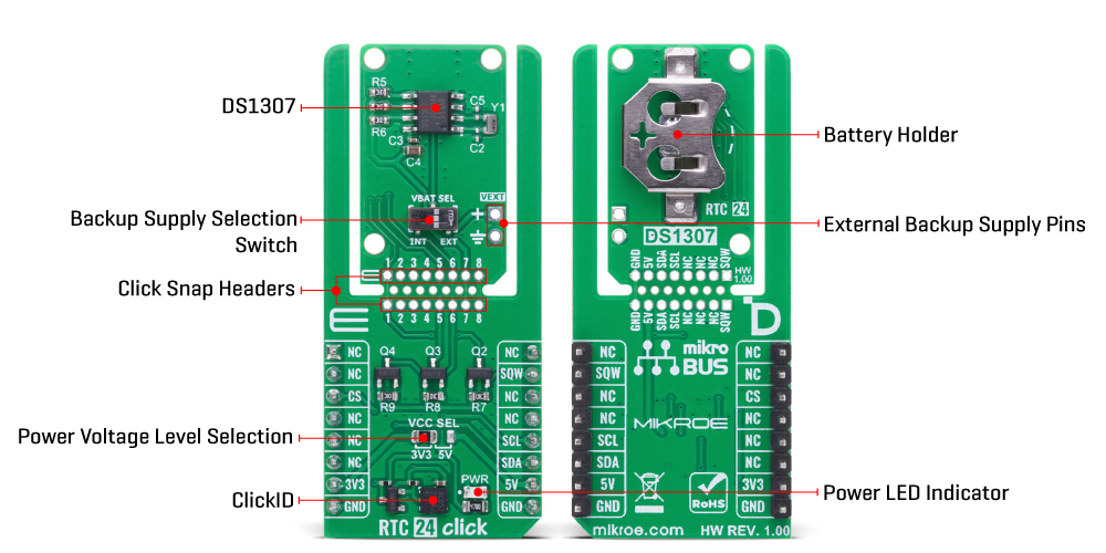
RTC 24 Click 基于 Analog Devices 的 DS1307 串行实时时钟(RTC)模块,集成 64x8 位电池供电非易失性 SRAM,并具备完整的 BCD 编码时钟/日历功能。该板为嵌入式应用提供高度精准的实时时钟与日历功能,即使在断电期间也能持续计时,确保时间数据完整无误。DS1307 支持完整的时间记录,包括秒、分、时、星期、日期、月份与年份,并内建逻辑自动处理每月结束的日期调整,能够识别少于 31 天的月份并支持闰年补偿(有效至 2100 年)。设备支持 24 小时与 12 小时制(带 AM/PM 指示),可灵活适配不同地区或应用的时间显示需求。该 Click 板采用支持 MIKROE 全新结构特性的 “Click Snap” 格
式。与传统 Click 板不同,Click Snap 设计允许用户断开 PCB,将主传感器区域独立出来进行灵活部署。通过访问 Snap 区域 1–8 号引脚,DS1307 可实现自主运行。此外,Snap 区域还预留固定螺丝孔位,方便将其可靠安装在所需位置。与主控 MCU 的通信通过标准 I2C 接口实现,确保集成过程简便、数据传输可靠。除 I2C 引脚外,RTC 24 Click 还使用 SQW 引脚,可输出四种可选的方波频率:1Hz、4kHz、8kHz 或 32kHz。此功能不仅可用于提供准确的时钟信号,还能作为复杂系统中同步用途的输出驱动。板载还集成了 VBAT SEL 开关,用于选择 RTC 模块的备用电源。用户可在板载锂电池与通过 VEXT 引脚提供的外
部 3V 后备电源之间切换,以实现灵活的供电管理。DS1307 内建电源检测电路,在主电源断电时会自动切换至所选备用电源,持续保持计时功能不中断。丰富的功能使 RTC 24 Click 成为数据记录器、计量系统、工业自动化以及所有需持续稳定实时时间追踪的嵌入式系统的理想解决方案。该 Click board™ 支持 3.3V 或 5V 逻辑电压工作,可通过 VCC SEL 跳线进行选择,兼容不同电压等级的 MCU 接口。此外,该板附带开发库,包含易于使用的函数与示例代码,供开发人员参考与快速集成使用。
功能概述
开发板
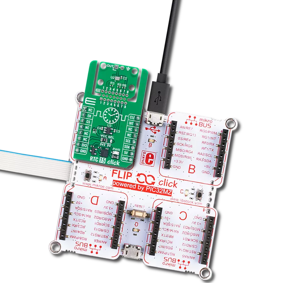
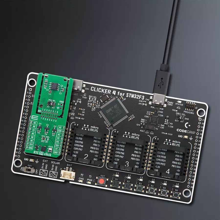
Clicker 4 for STM32F3 是一款紧凑型开发板,作为完整的解决方案而设计,可帮助用户快速构建具备独特功能的定制设备。该板搭载 STMicroelectronics 的 STM32F302VCT6 微控制器,配备四个 mikroBUS™ 插槽用于连接 Click boards™、完善的电源管理功能以及其他实用资源,是快速开发各类应用的理想平台。其核心 MCU STM32F302VCT6 基于高性能
Arm® Cortex®-M4 32 位处理器,运行频率高达 168MHz,处理能力强大,能够满足各种高复杂度任务的需求,使 Clicker 4 能灵活适应多种应用场景。除了两个 1x20 引脚排针外,板载最显著的连接特性是四个增强型 mikroBUS™ 插槽,支持接入数量庞大的 Click boards™ 生态系统,该生态每日持续扩展。Clicker 4 各功能区域标识清晰,界面直观简洁,极大
提升使用便捷性和开发效率。Clicker 4 的价值不仅在于加速原型开发与应用构建阶段,更在于其作为独立完整方案可直接集成至实际项目中,无需额外硬件修改。四角各设有直径 4.2mm(0.165")的安装孔,便于通过螺丝轻松固定。对于多数应用,只需配套一个外壳,即可将 Clicker 4 开发板转化为完整、实用且外观精美的定制系统。

微控制器概述
MCU卡片 / MCU

建筑
ARM Cortex-M4
MCU 内存 (KB)
256
硅供应商
STMicroelectronics
引脚数
100
RAM (字节)
40960
使用的MCU引脚
mikroBUS™映射器
“仔细看看!”
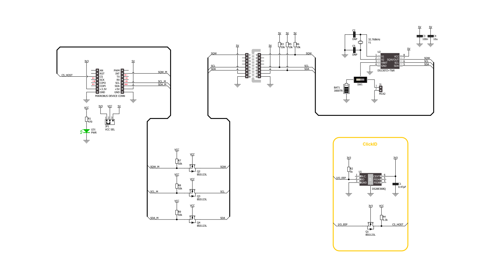
Click board™ 原理图
一步一步来
项目组装

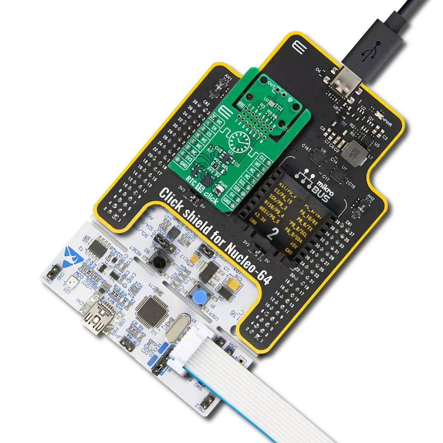
从选择您的开发板和Click板™开始。以CLICKER 4 for STM32F302VCT6作为您的开发板开始。


实时跟踪您的结果
应用程序输出
1. 应用程序输出 - 在调试模式下,“应用程序输出”窗口支持实时数据监控,直接提供执行结果的可视化。请按照提供的教程正确配置环境,以确保数据正确显示。

2. UART 终端 - 使用UART Terminal通过USB to UART converter监视数据传输,实现Click board™与开发系统之间的直接通信。请根据项目需求配置波特率和其他串行设置,以确保正常运行。有关分步设置说明,请参考提供的教程。

3. Plot 输出 - Plot功能提供了一种强大的方式来可视化实时传感器数据,使趋势分析、调试和多个数据点的对比变得更加直观。要正确设置,请按照提供的教程,其中包含使用Plot功能显示Click board™读数的分步示例。在代码中使用Plot功能时,请使用以下函数:plot(insert_graph_name, variable_name);。这是一个通用格式,用户需要将“insert_graph_name”替换为实际图表名称,并将“variable_name”替换为要显示的参数。

软件支持
库描述
RTC 24 Click 演示应用程序使用 NECTO Studio开发,确保与 mikroSDK 的开源库和工具兼容。该演示设计为即插即用,可与所有具有 mikroBUS™ 插座的 开发板、入门板和 mikromedia 板完全兼容,用于快速实现和测试。
示例描述
本示例演示如何使用 RTC 24 Click 板来初始化设备并设置当前的时间与日期。程序将持续读取并每秒通过方波引脚更新并显示当前时间与日期。
关键功能:
rtc24_cfg_setup- 初始化 Click 配置结构体为默认值。rtc24_init- 初始化 RTC 24 Click 所需的全部引脚和外设。rtc24_default_cfg- 执行 RTC 24 Click 的默认配置。rtc24_set_time- 设置 RTC 中的当前时间(小时、分钟、秒)。rtc24_read_time- 读取 RTC 中的当前时间(小时、分钟、秒)。rtc24_read_date- 读取 RTC 中的当前日期(日期、星期、月份、年份)。
应用初始化
初始化日志记录器与 RTC 24 Click 驱动程序,应用默认配置,并设置起始时间与日期。
应用任务
等待 1Hz 方波信号的到来,每次触发后读取并显示当前的时间与日期。
开源
代码示例
完整的应用程序代码和一个现成的项目可以通过NECTO Studio包管理器直接安装到NECTO Studio。 应用程序代码也可以在MIKROE的GitHub账户中找到。
/*!
 * @file main.c
 * @brief RTC 24 Click example
 *
 * # Description
 * This example demonstrates the use of the RTC 24 Click board by initializing
 * the device and setting up the current time and date. It continuously
 * reads and displays the updated time and date every second using the square wave pin.
 *
 * The demo application is composed of two sections:
 *
 * ## Application Init
 * Initializes the logger and the RTC 24 Click driver, applies the default configuration,
 * and sets the starting time and date.
 *
 * ## Application Task
 * Waits for a 1 Hz square wave signal and then reads and displays the current time and date.
 *
 * @author Stefan Filipovic
 *
 */

#include "board.h"
#include "log.h"
#include "rtc24.h"

static rtc24_t rtc24;
static log_t logger;
static rtc24_time_t time;
static rtc24_date_t date;

/**
 * @brief RTC 24 get day of week name function.
 * @details This function returns the name of day of the week as a string.
 * @param[in] ctx : Click context object.
 * See #rtc24_t object definition for detailed explanation.
 * @param[in] day_of_week : Day of week decimal value.
 * @return Name of day as a string.
 * @note None.
 */
static uint8_t *rtc24_get_day_of_week_name ( uint8_t day_of_week );

void application_init ( void )
{
    log_cfg_t log_cfg;  /**< Logger config object. */
    rtc24_cfg_t rtc24_cfg;  /**< Click config object. */

    /**
     * Logger initialization.
     * Default baud rate: 124200
     * Default log level: LOG_LEVEL_DEBUG
     * @note If USB_UART_RX and USB_UART_TX
     * are defined as HAL_PIN_NC, you will
     * need to define them manually for log to work.
     * See @b LOG_MAP_USB_UART macro definition for detailed explanation.
     */
    LOG_MAP_USB_UART( log_cfg );
    log_init( &logger, &log_cfg );
    log_info( &logger, " Application Init " );

    // Click initialization.
    rtc24_cfg_setup( &rtc24_cfg );
    RTC24_MAP_MIKROBUS( rtc24_cfg, MIKROBUS_1 );
    if ( I2C_MASTER_ERROR == rtc24_init( &rtc24, &rtc24_cfg ) )
    {
        log_error( &logger, " Communication init." );
        for ( ; ; );
    }

    if ( RTC24_ERROR == rtc24_default_cfg ( &rtc24 ) )
    {
        log_error( &logger, " Default configuration." );
        for ( ; ; );
    }

    time.hour = 23;
    time.minute = 59;
    time.second = 50;
    if ( RTC24_OK == rtc24_set_time ( &rtc24, &time ) )
    {
        log_printf( &logger, " Set time: %.2u:%.2u:%.2u\r\n",
                    ( uint16_t ) time.hour, ( uint16_t ) time.minute, ( uint16_t ) time.second );
    }
    date.day_of_week = RTC24_TUESDAY;
    date.day = 31;
    date.month = 12;
    date.year = 24;
    if ( RTC24_OK == rtc24_set_date ( &rtc24, &date ) )
    {
        log_printf( &logger, " Set date: %s, %.2u.%.2u.20%.2u.\r\n",
                    rtc24_get_day_of_week_name ( date.day_of_week ),
                    ( uint16_t ) date.day, ( uint16_t ) date.month, ( uint16_t ) date.year );
    }

    log_info( &logger, " Application Task " );
}

void application_task ( void )
{
    // Wait for a square wave output configured at 1 Hz
    while ( rtc24_get_sqw_pin ( &rtc24 ) );
    while ( !rtc24_get_sqw_pin ( &rtc24 ) );

    if ( RTC24_OK == rtc24_read_time ( &rtc24, &time ) )
    {
        log_printf( &logger, " Time: %.2u:%.2u:%.2u\r\n",
                    ( uint16_t ) time.hour, ( uint16_t ) time.minute, ( uint16_t ) time.second );
    }
    if ( RTC24_OK == rtc24_read_date ( &rtc24, &date ) )
    {
        log_printf( &logger, " Date: %s, %.2u.%.2u.20%.2u.\r\n\n",
                    rtc24_get_day_of_week_name ( date.day_of_week ),
                    ( uint16_t ) date.day, ( uint16_t ) date.month, ( uint16_t ) date.year );
    }
}

int main ( void )
{
    /* Do not remove this line or clock might not be set correctly. */
    #ifdef PREINIT_SUPPORTED
    preinit();
    #endif

    application_init( );

    for ( ; ; )
    {
        application_task( );
    }

    return 0;
}

static uint8_t *rtc24_get_day_of_week_name ( uint8_t day_of_week )
{
    switch ( day_of_week )
    {
        case RTC24_MONDAY:
        {
            return "Monday";
        }
        case RTC24_TUESDAY:
        {
            return "Tuesday";
        }
        case RTC24_WEDNESDAY:
        {
            return "Wednesday";
        }
        case RTC24_THURSDAY:
        {
            return "Thursday";
        }
        case RTC24_FRIDAY:
        {
            return "Friday";
        }
        case RTC24_SATURDAY:
        {
            return "Saturday";
        }
        case RTC24_SUNDAY:
        {
            return "Sunday";
        }
        default:
        {
            return "Unknown";
        }
    }
}

// ------------------------------------------------------------------------ END
额外支持
资源
类别:RTC