使用 IQS390 和 STM32L496AG 为嵌入式应用提供灵敏触觉反馈
面向嵌入式应用的低功耗触觉反馈解决方案,提升用户交互体验
已发布 8月 18, 2025
点击板
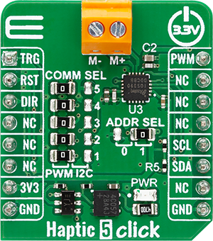
Haptic 5 Click
开发板
Discovery kit with STM32L496AG MCU
编译器
NECTO Studio
微控制器单元
STM32L496AG
响应式触觉反馈,具备实时自动共振追踪与超低功耗运行,带来更出色的触觉用户交互体验
A
A
硬件概览
它是如何工作的?
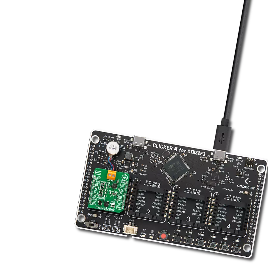
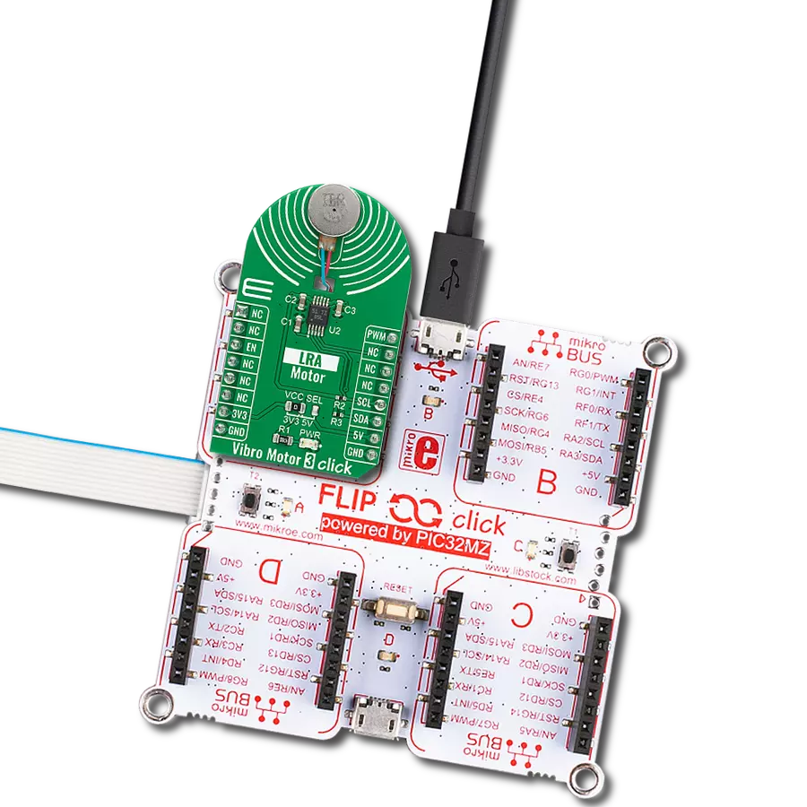
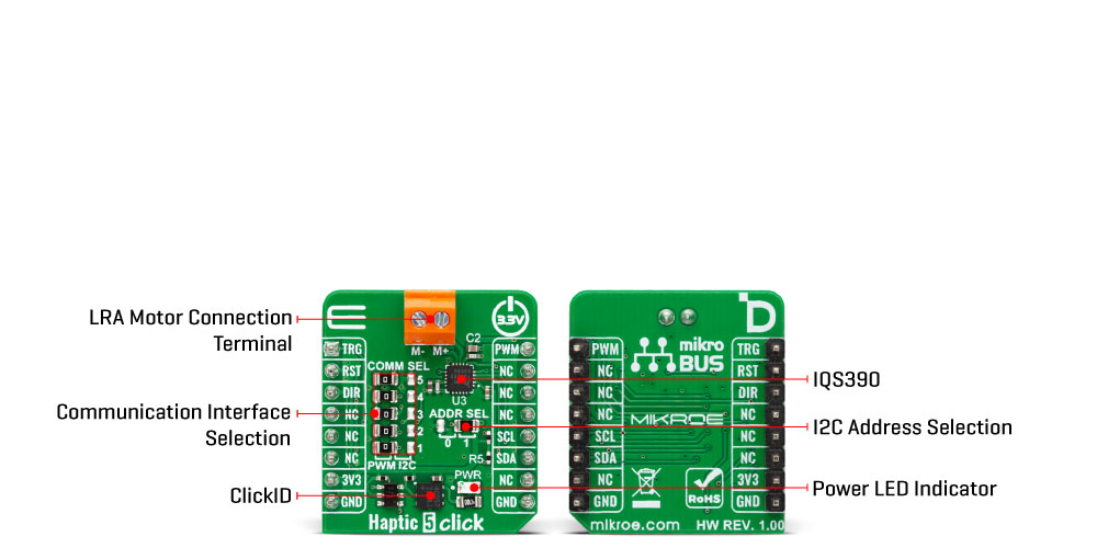
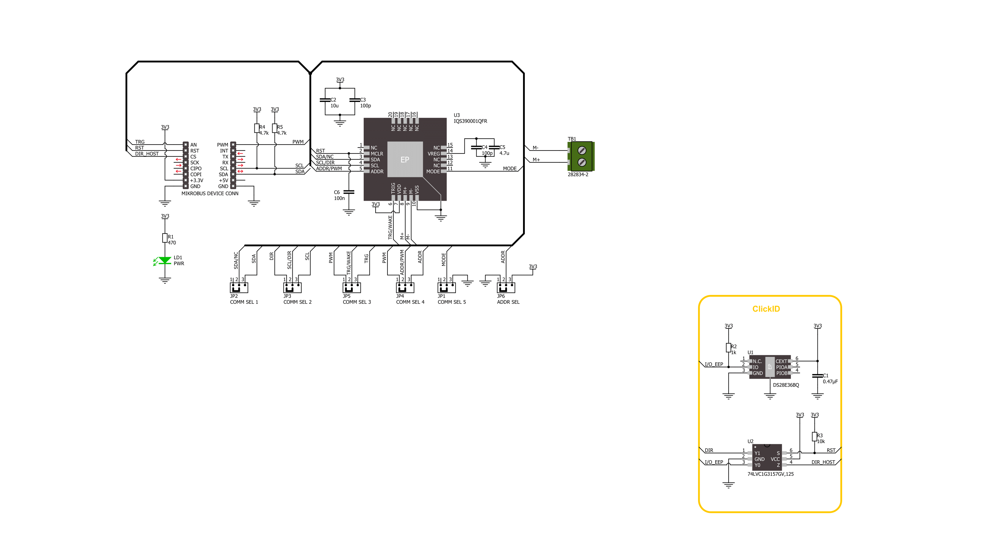
Haptic 5 Click 基于 Azoteq 的 IQS390 触觉驱动芯片,旨在通过线性谐振驱动器(LRA)提供高性能的触觉反馈。该板支持两种工作模式 —— I2C 和 PWM —— 可通过 COMM SEL 跳线选择。为确保正常运行,所有跳线必须统一设置在同一模式一侧。在 I2C 模式下,IQS390 采用实时闭环自动谐振算法,动态追踪并匹配所连接 LRA 电机的谐振频率,从而实现高效且一致的振动输出。Haptic 5 Click 非常适用于需要
精确和响应迅速的触觉反馈的应用,如鼠标滚轮滚动效果、触控板交互、门铃通知以及薄膜按键。I2C 接口支持最高 1 MHz 的快速模式+(Fast Mode Plus)通信速率,可通过 ADDR SEL 跳线配置可选的 I2C 地址,方便灵活地集成到各种系统中。此外,IQS390 包含一个专用的 RST 引脚用于硬件复位,触觉脉冲可通过 I2C 指令触发,也可以通过 TRG 引脚外部触发。在 PWM 模式下,该板接受外部脉宽调制信号,
并通过 DIR 引脚输入电机驱动方向。两种工作模式均具备自动电源模式管理功能,包括在空闲期间降低能耗的超低功耗状态。此 Click 板仅支持 3.3V 逻辑电压工作。在使用其他逻辑电平的 MCU 前,必须进行适当的电压电平转换。该板还配有一个包含函数和示例代码的库,可作为后续开发的参考。
功能概述
开发板
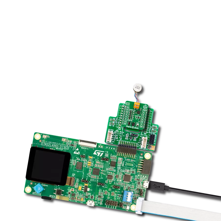
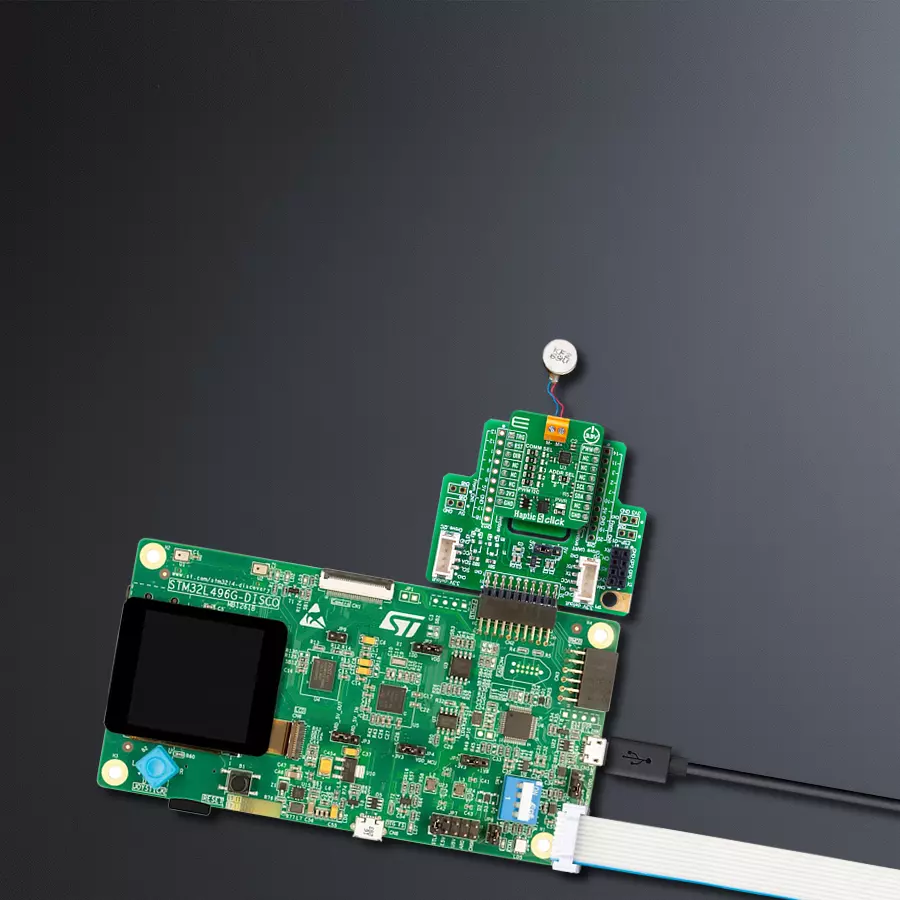
32L496GDISCOVERY Discovery 套件是一款功能全面的演示和开发平台,专为搭载 Arm® Cortex®-M4 内核的 STM32L496AG 微控制器设计。该套件适用于需要在高性能、先进图形处理和超低功耗之间取得平衡的应用,支持无缝原型开发,适用于各种嵌入式解决方案。STM32L496AG 采用创新的节能架构,集成
了扩展 RAM 和 Chrom-ART 图形加速器,在提升图形性能的同时保持低功耗,使其特别适用于音频处理、图形用户界面和实时数据采集等对能效要求较高的应用。为了简化开发流程,该开发板配备了板载 ST-LINK/V2-1 调试器/编程器,提供即插即用的调试和编程体验,使用户无需额外硬件即可轻松加载、调
试和测试应用程序。凭借低功耗特性、增强的内存能力以及内置调试工具,32L496GDISCOVERY 套件是开发先进嵌入式系统、实现高效能解决方案的理想选择。

微控制器概述
MCU卡片 / MCU

建筑
ARM Cortex-M4
MCU 内存 (KB)
1024
硅供应商
STMicroelectronics
引脚数
169
RAM (字节)
327680
你完善了我!
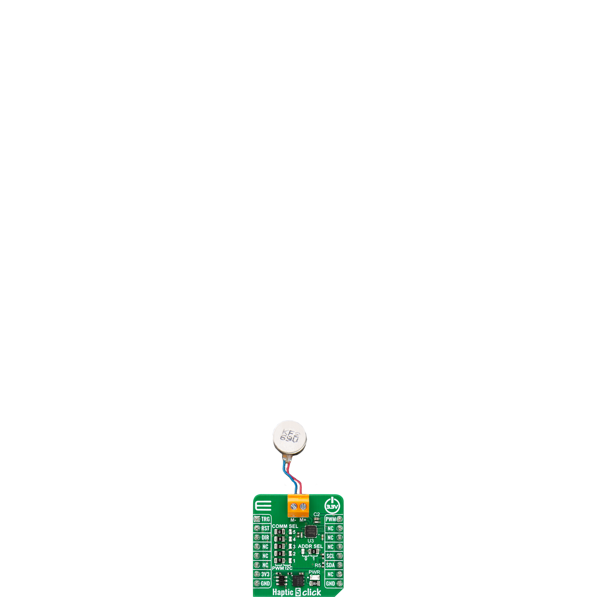
配件
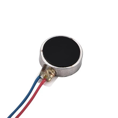
LRA0825BC-0167F 是一款精密线性谐振执行器(LRA),专为紧凑型触觉反馈应用而设计,直径 8mm、厚度 2.5mm。该器件针对 Z 轴振动输出进行了优化,工作在 240 ±10Hz 的谐振频率下,可产生至少 0.7 Grms 的振动加速度。在 1.2 Vrms AC 额定电压和最大 90 mA 电流消耗下,能够实现灵敏的响应性能,其上升时间最长 50 毫秒、下降时间最长 80 毫秒。其 0.1 至 1.25 Vrms AC 的工作电压范围为控制提供了灵活性,非常适合用于可穿戴设备、手持仪器及其他空间受限、需要精确高效触觉反馈的设计。
使用的MCU引脚
mikroBUS™映射器
“仔细看看!”
Click board™ 原理图
一步一步来
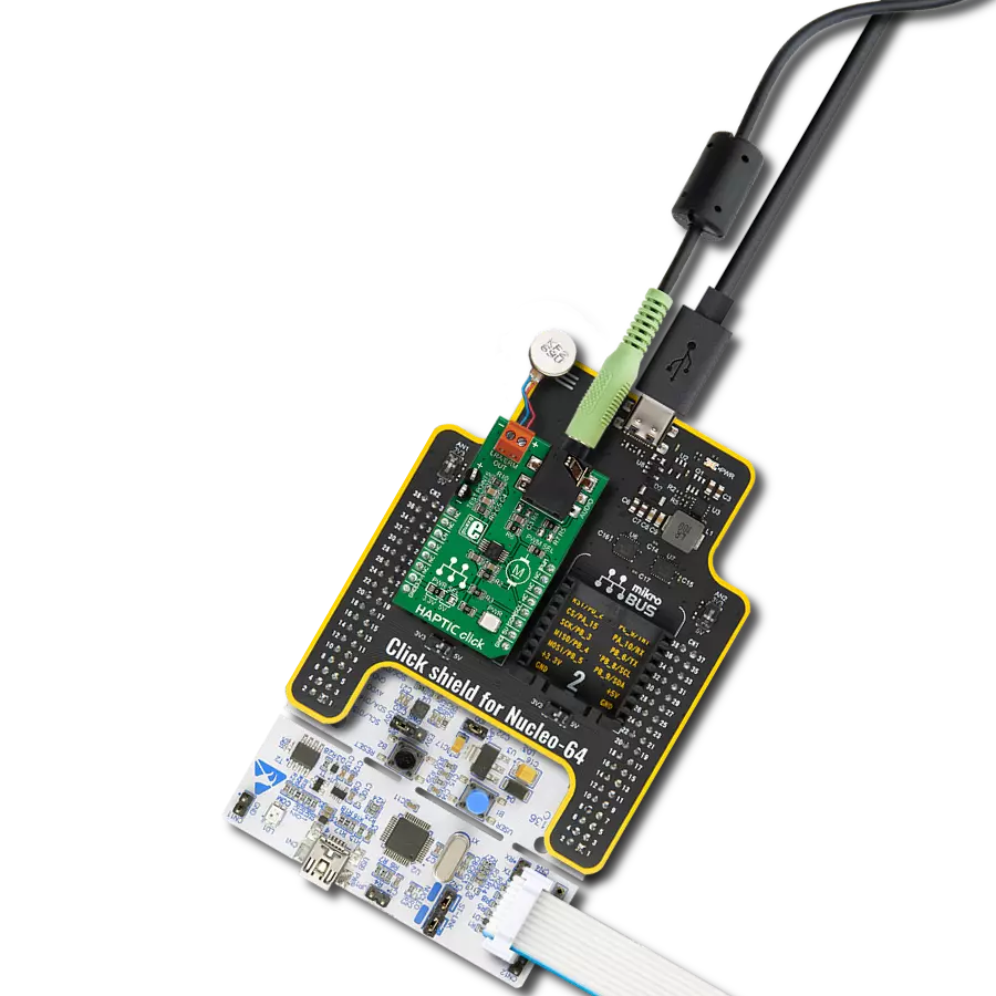
项目组装

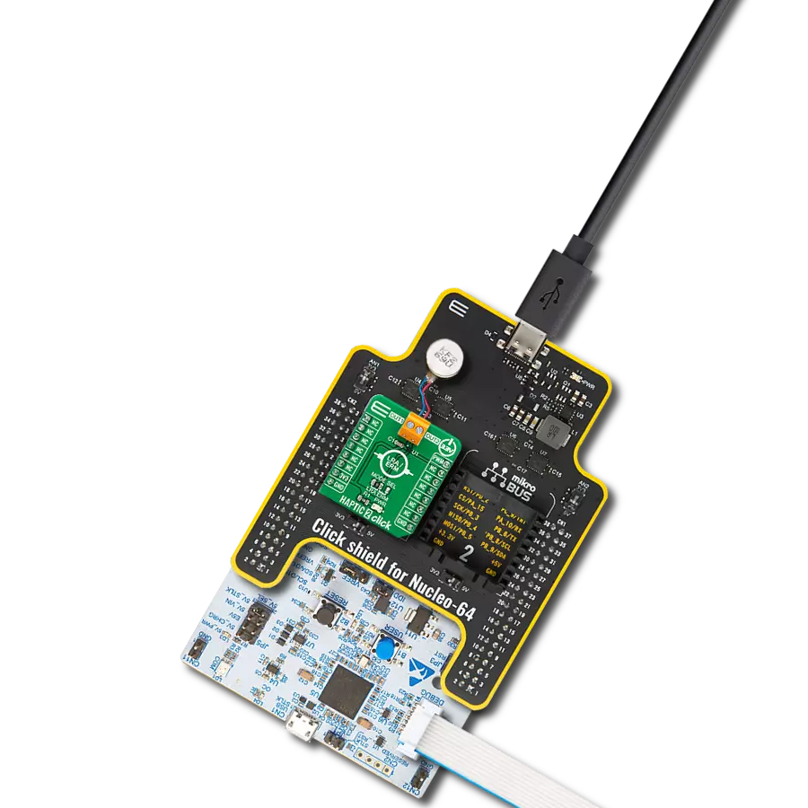
从选择您的开发板和Click板™开始。以Discovery kit with STM32L496AG MCU作为您的开发板开始。


实时跟踪您的结果
应用程序输出
1. 应用程序输出 - 在调试模式下,“应用程序输出”窗口支持实时数据监控,直接提供执行结果的可视化。请按照提供的教程正确配置环境,以确保数据正确显示。

2. UART 终端 - 使用UART Terminal通过USB to UART converter监视数据传输,实现Click board™与开发系统之间的直接通信。请根据项目需求配置波特率和其他串行设置,以确保正常运行。有关分步设置说明,请参考提供的教程。

3. Plot 输出 - Plot功能提供了一种强大的方式来可视化实时传感器数据,使趋势分析、调试和多个数据点的对比变得更加直观。要正确设置,请按照提供的教程,其中包含使用Plot功能显示Click board™读数的分步示例。在代码中使用Plot功能时,请使用以下函数:plot(insert_graph_name, variable_name);。这是一个通用格式,用户需要将“insert_graph_name”替换为实际图表名称,并将“variable_name”替换为要显示的参数。

软件支持
库描述
Haptic 5 Click 演示应用程序使用 NECTO Studio开发,确保与 mikroSDK 的开源库和工具兼容。该演示设计为即插即用,可与所有具有 mikroBUS™ 插座的 开发板、入门板和 mikromedia 板完全兼容,用于快速实现和测试。
示例描述
本示例演示了如何控制 Haptic 5 Click 板。在 I2C 模式下,示例通过周期性切换触觉触发引脚,产生振动脉冲;在 PWM 模式下,示例逐步增加和减少输出占空比以调节振动强度,并在占空比降为 0% 时切换振动方向。
关键功能:
haptic5_cfg_setup- 初始化 Click 配置结构体为默认值的函数。haptic5_init- 初始化此 Click 板所需的所有引脚和外设的函数。haptic5_default_cfg- 执行 Haptic 5 Click 板默认配置的函数。haptic5_set_duty_cycle- 设置 PWM 占空比的函数。haptic5_toggle_dir- 切换 DIR 引脚状态(振动方向)的函数。
应用初始化
初始化日志记录器与 Click 板驱动,并应用默认配置。
应用任务
根据所选的通信接口(I2C 或 PWM),切换触觉触发信号(I2C 模式),或更改 PWM 占空比并在需要时切换方向(PWM 模式)。
开源
代码示例
完整的应用程序代码和一个现成的项目可以通过NECTO Studio包管理器直接安装到NECTO Studio。 应用程序代码也可以在MIKROE的GitHub账户中找到。
/*!
 * @file main.c
 * @brief Haptic 5 Click example
 *
 * # Description
 * This example demonstrates the control of the Haptic 5 Click board.
 * In I2C mode, the example toggles the haptic trigger pin periodically to generate vibration pulses.
 * In PWM mode, it gradually increases and decreases the output duty cycle to modulate the vibration intensity,
 * while toggling the direction when the duty reaches 0%.
 *
 * The demo application is composed of two sections :
 *
 * ## Application Init
 * Initializes the logger and the Click board driver, and applies the default configuration.
 *
 * ## Application Task
 * Depending on the selected communication interface (I2C or PWM), toggles the haptic trigger (I2C),
 * or changes PWM duty cycle and direction (PWM).
 *
 * @note
 * The mode is selected via the @b HAPTIC5_DEFAULT_COM macro. Ensure proper configuration and wiring
 * based on the selected mode before running the example.
 *
 * @author Stefan Filipovic
 *
 */

#include "board.h"
#include "log.h"
#include "haptic5.h"

static haptic5_t haptic5;
static log_t logger;

void application_init ( void )
{
    log_cfg_t log_cfg;  /**< Logger config object. */
    haptic5_cfg_t haptic5_cfg;  /**< Click config object. */

    /**
     * Logger initialization.
     * Default baud rate: 115200
     * Default log level: LOG_LEVEL_DEBUG
     * @note If USB_UART_RX and USB_UART_TX
     * are defined as HAL_PIN_NC, you will
     * need to define them manually for log to work.
     * See @b LOG_MAP_USB_UART macro definition for detailed explanation.
     */
    LOG_MAP_USB_UART( log_cfg );
    log_init( &logger, &log_cfg );
    log_info( &logger, " Application Init " );

    // Click initialization.
    haptic5_cfg_setup( &haptic5_cfg );
    HAPTIC5_MAP_MIKROBUS( haptic5_cfg, MIKROBUS_1 );
    if ( PWM_ERROR == haptic5_init( &haptic5, &haptic5_cfg ) )
    {
        log_error( &logger, " Communication init." );
        for ( ; ; );
    }

    if ( HAPTIC5_ERROR == haptic5_default_cfg ( &haptic5 ) )
    {
        log_error( &logger, " Default configuration." );
        for ( ; ; );
    }

    log_info( &logger, " Application Task " );
}

void application_task ( void )
{
#if ( HAPTIC5_DEFAULT_COM == HAPTIC5_COM_I2C )
    log_printf( &logger, " Haptic state: Active\r\n\n" );
    haptic5_set_trg_high ( &haptic5 );
    Delay_ms ( 1000 );
    log_printf( &logger, " Haptic state: Idle\r\n\n" );
    haptic5_set_trg_low ( &haptic5 );
    Delay_ms ( 1000 );
#else
    static int8_t duty_cnt = 1;
    static int8_t duty_inc = 1;
    float duty = duty_cnt / 10.0;

    haptic5_set_duty_cycle ( &haptic5, duty );
    log_printf( &logger, "> Duty: %d%%\r\n", ( uint16_t )( duty_cnt * 10 ) );

    Delay_ms ( 500 );

    if ( 10 == duty_cnt )
    {
        duty_inc = -1;
    }
    else if ( 0 == duty_cnt )
    {
        duty_inc = 1;
        haptic5_toggle_dir ( &haptic5 );
    }
    duty_cnt += duty_inc;
#endif
}

int main ( void )
{
    /* Do not remove this line or clock might not be set correctly. */
    #ifdef PREINIT_SUPPORTED
    preinit();
    #endif

    application_init( );

    for ( ; ; )
    {
        application_task( );
    }

    return 0;
}

// ------------------------------------------------------------------------ END
额外支持
资源
类别:触觉