使用 MYWGC3R53FF 和 STM32L496AG 从单一电源提供四路稳压输出
面向复杂嵌入式系统的多输出电源调节解决方案
已发布 7月 28, 2025
点击板
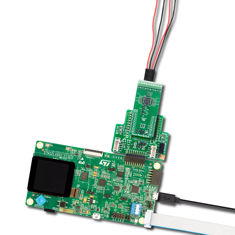
Smart Buck 7 Click
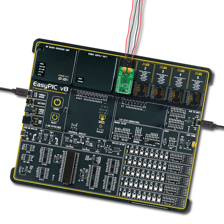
开发板
Discovery kit with STM32L496AG MCU
编译器
NECTO Studio
微控制器单元
STM32L496AG
非常适合为具有多个电压域的复杂嵌入式系统供电
A
A
硬件概览
它是如何工作的?
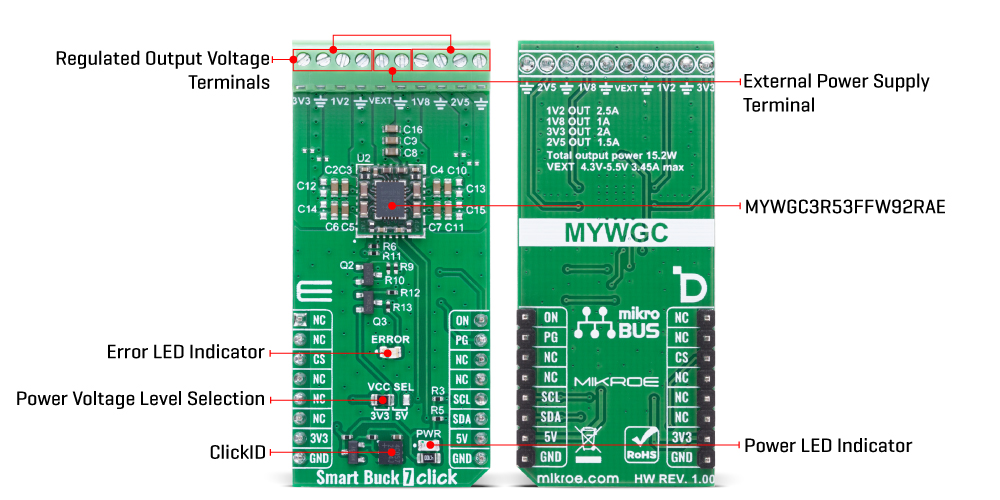
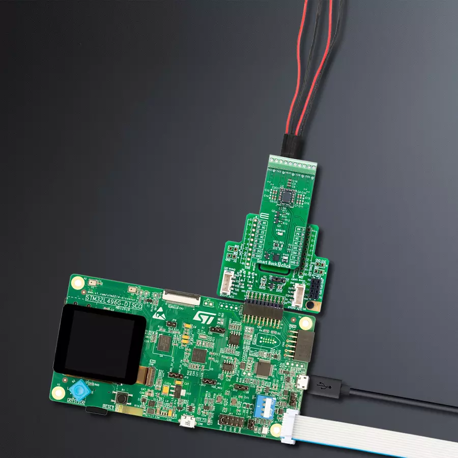
Smart Buck 7 Click 是一款基于 Murata 的 MYWGC3R53FF MonoBK™ 多输出 DC-DC 转换模块的紧凑型附加板,可从单一电源源精确地生成多个稳压输出电压。MYWGC3R53FF 支持 4.3V 至 5.5V 的外部输入电压(接入 VEXT 端子),最大输入电流为 3.45A,采用固定频率的同步降压拓扑结构,生成四路独立稳压输出:1.2V@2.5A(端子 1V2)、1.8V@1A(端子 1V8)、2.5V@1.5A(端子 2V5)、3.3V@2A(端子 3V3),总功率输出最高可达 15.2W。这款 Click 板特别适用于为 FPGA、
CPU、可编程逻辑器件、分布式总线架构(DBA)系统以及广泛应用于数据通信和电信基础设施中的混合电压平台供电。MYWGC3R53FF 通过 I²C 兼容串行接口与主控 MCU 通信,支持标准(100kHz)和快速(400kHz)模式,可用于输出电压控制及状态寄存器监测。板载 ON 控制引脚允许外部开关整个电源模块,适用于软件控制的电源排序场景中的电源域管理。此外,该模块还提供 PG(Power Good)输出引脚,同时连接至板载红色 LED(标记为 ERROR),用于实时指示电压异常或故障情况——例如当一条或
多条输出轨不在正常调节范围或被禁用时。为保障系统安全,MYWGC3R53FF 集成多种保护机制,包括输入欠压锁定(UVLO)防止低压运行,输出短路保护、过流保护(OCP)、过压保护(OVP)以及过温保护(OTP)——触发热关断以确保器件可靠性和系统安全性。Smart Buck 7 Click 支持 3.3V 与 5V 逻辑电平输入,可通过 VCC SEL 跳帽进行切换,从而兼容不同主控 MCU 的通信需求。此外,MikroE 还为该板提供功能完整的软件库及示例代码,便于用户进行快速开发和集成。
功能概述
开发板
32L496GDISCOVERY Discovery 套件是一款功能全面的演示和开发平台,专为搭载 Arm® Cortex®-M4 内核的 STM32L496AG 微控制器设计。该套件适用于需要在高性能、先进图形处理和超低功耗之间取得平衡的应用,支持无缝原型开发,适用于各种嵌入式解决方案。STM32L496AG 采用创新的节能架构,集成
了扩展 RAM 和 Chrom-ART 图形加速器,在提升图形性能的同时保持低功耗,使其特别适用于音频处理、图形用户界面和实时数据采集等对能效要求较高的应用。为了简化开发流程,该开发板配备了板载 ST-LINK/V2-1 调试器/编程器,提供即插即用的调试和编程体验,使用户无需额外硬件即可轻松加载、调
试和测试应用程序。凭借低功耗特性、增强的内存能力以及内置调试工具,32L496GDISCOVERY 套件是开发先进嵌入式系统、实现高效能解决方案的理想选择。

微控制器概述
MCU卡片 / MCU

建筑
ARM Cortex-M4
MCU 内存 (KB)
1024
硅供应商
STMicroelectronics
引脚数
169
RAM (字节)
327680
使用的MCU引脚
mikroBUS™映射器
“仔细看看!”
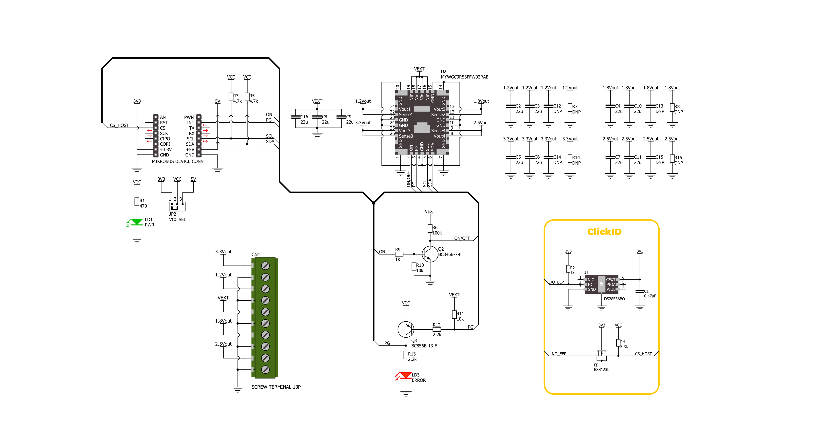
Click board™ 原理图
一步一步来
项目组装

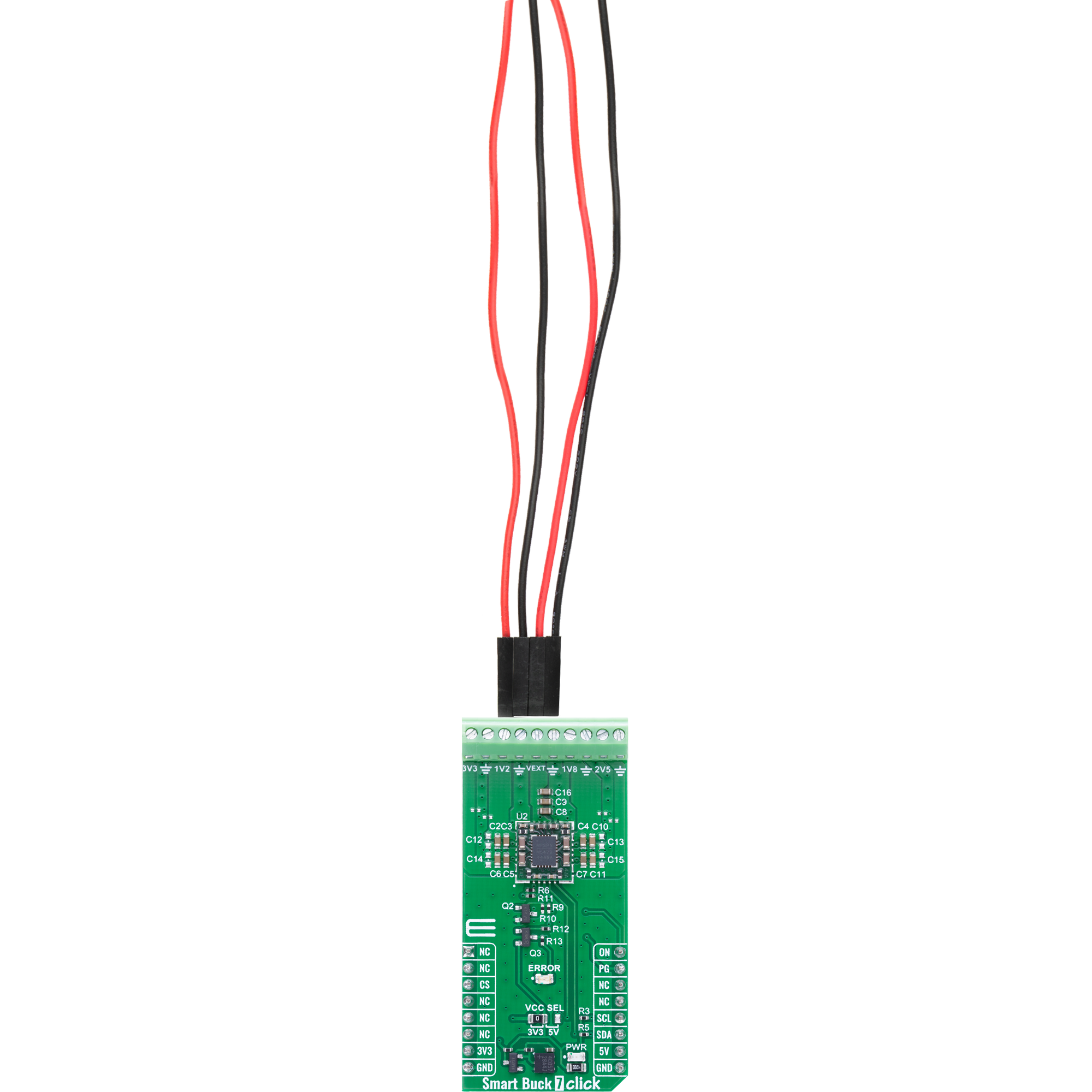
从选择您的开发板和Click板™开始。以Discovery kit with STM32L496AG MCU作为您的开发板开始。


实时跟踪您的结果
应用程序输出
1. 应用程序输出 - 在调试模式下,“应用程序输出”窗口支持实时数据监控,直接提供执行结果的可视化。请按照提供的教程正确配置环境,以确保数据正确显示。

2. UART 终端 - 使用UART Terminal通过USB to UART converter监视数据传输,实现Click board™与开发系统之间的直接通信。请根据项目需求配置波特率和其他串行设置,以确保正常运行。有关分步设置说明,请参考提供的教程。

3. Plot 输出 - Plot功能提供了一种强大的方式来可视化实时传感器数据,使趋势分析、调试和多个数据点的对比变得更加直观。要正确设置,请按照提供的教程,其中包含使用Plot功能显示Click board™读数的分步示例。在代码中使用Plot功能时,请使用以下函数:plot(insert_graph_name, variable_name);。这是一个通用格式,用户需要将“insert_graph_name”替换为实际图表名称,并将“variable_name”替换为要显示的参数。

软件支持
库描述
Smart Buck 7 Click 演示应用程序使用 NECTO Studio开发,确保与 mikroSDK 的开源库和工具兼容。该演示设计为即插即用,可与所有具有 mikroBUS™ 插座的 开发板、入门板和 mikromedia 板完全兼容,用于快速实现和测试。
示例描述
本示例演示了如何使用 Smart Buck 7 Click 扩展板。应用程序会周期性地启用不同组合的四路降压输出(1.2V、1.8V、2.5V 和 3.3V),并记录当前激活的输出。同时,它还会监测 PG(Power Good)引脚状态,并在出现故障(如欠压或过温)时进行日志记录。
关键功能:
smartbuck7_cfg_setup- 初始化 Click 配置结构体为默认值。smartbuck7_init- 初始化使用该 Click 板所需的所有引脚和外设。smartbuck7_default_cfg- 执行 Smart Buck 7 Click 的默认配置流程。smartbuck7_get_pg_pin- 读取 PG 引脚的逻辑电平状态。smartbuck7_enable_buck- 通过设置控制位启用一个或多个降压稳压器。smartbuck7_disable_buck- 通过清除控制位禁用一个或多个降压稳压器。
应用初始化
初始化日志模块和 Smart Buck 7 Click 驱动,并应用默认配置。
应用任务
循环启用不同组合的降压输出,记录当前激活的电压轨,检查 PG 引脚以检测故障状态,并在检测到故障(如欠压或过温)时记录相应信息。
开源
代码示例
完整的应用程序代码和一个现成的项目可以通过NECTO Studio包管理器直接安装到NECTO Studio。 应用程序代码也可以在MIKROE的GitHub账户中找到。
/*!
 * @file main.c
 * @brief Smart Buck 7 Click example
 *
 * # Description
 * This example demonstrates the use of the Smart Buck 7 Click board. The application cyclically enables
 * different combinations of the four buck converter outputs (1.2V, 1.8V, 2.5V, and 3.3V) and logs which
 * outputs are currently active. It also monitors the PG (Power Good) pin and logs any fault conditions,
 * including undervoltage and over-temperature events.
 *
 * The demo application is composed of two sections :
 *
 * ## Application Init
 * Initializes the logger and the Smart Buck 7 Click driver, and applies the default configuration.
 *
 * ## Application Task
 * Cycles through various buck output combinations, logs the enabled outputs,
 * checks the PG pin for fault indication, and logs any detected fault status.
 *
 * @note
 * Ensure all outputs are properly loaded and that the input voltage is within recommended levels
 * to evaluate fault detection reliably.
 *
 * @author Stefan Filipovic
 *
 */

#include "board.h"
#include "log.h"
#include "smartbuck7.h"

static smartbuck7_t smartbuck7;
static log_t logger;

/**
 * @brief Smart Buck 7 display status function.
 * @details This function parses and logs all detected status flags from the Smart Buck 7 Click board
 * including over-temperature and power-good conditions.
 * @param[in] status : Status register structure.
 * See #smartbuck7_status_t object definition for detailed explanation.
 * @return None.
 * @note This function outputs human-readable messages via the logger for each active status flag.
 */
static void smartbuck7_display_status ( smartbuck7_status_t status );

void application_init ( void )
{
    log_cfg_t log_cfg;  /**< Logger config object. */
    smartbuck7_cfg_t smartbuck7_cfg;  /**< Click config object. */

    /**
     * Logger initialization.
     * Default baud rate: 115200
     * Default log level: LOG_LEVEL_DEBUG
     * @note If USB_UART_RX and USB_UART_TX
     * are defined as HAL_PIN_NC, you will
     * need to define them manually for log to work.
     * See @b LOG_MAP_USB_UART macro definition for detailed explanation.
     */
    LOG_MAP_USB_UART( log_cfg );
    log_init( &logger, &log_cfg );
    log_info( &logger, " Application Init " );

    // Click initialization.
    smartbuck7_cfg_setup( &smartbuck7_cfg );
    SMARTBUCK7_MAP_MIKROBUS( smartbuck7_cfg, MIKROBUS_1 );
    if ( I2C_MASTER_ERROR == smartbuck7_init( &smartbuck7, &smartbuck7_cfg ) )
    {
        log_error( &logger, " Communication init." );
        for ( ; ; );
    }

    if ( SMARTBUCK7_ERROR == smartbuck7_default_cfg ( &smartbuck7 ) )
    {
        log_error( &logger, " Default configuration." );
        for ( ; ; );
    }

    log_info( &logger, " Application Task " );
}

void application_task ( void )
{
    smartbuck7_status_t status;
    static uint8_t buck_en = SMARTBUCK7_BUCK_4;
    if ( smartbuck7_get_pg_pin ( &smartbuck7 ) )
    {
        log_printf( &logger, "\r\n Fault indication detected via PG pin!\r\n" );
        if ( SMARTBUCK7_OK == smartbuck7_read_status ( &smartbuck7, &status ) )
        {
            smartbuck7_display_status ( status );
        }
        smartbuck7_clear_status( &smartbuck7 );
    }
    if ( buck_en > SMARTBUCK7_BUCK_ALL )
    {
        if ( SMARTBUCK7_OK == smartbuck7_disable_buck ( &smartbuck7, SMARTBUCK7_BUCK_ALL ) )
        {
            log_printf( &logger, "\r\n Outputs enabled: - NONE -\r\n" );
            buck_en = SMARTBUCK7_BUCK_4;
        }
    }
    else if ( SMARTBUCK7_OK == smartbuck7_enable_buck ( &smartbuck7, buck_en ) )
    {
        log_printf( &logger, "\r\n Outputs enabled: -" );
        if ( buck_en & SMARTBUCK7_BUCK_3 )
        {
            log_printf( &logger, " 3.3V -" );
        }
        if ( buck_en & SMARTBUCK7_BUCK_1 )
        {
            log_printf( &logger, " 1.2V -" );
        }
        if ( buck_en & SMARTBUCK7_BUCK_2 )
        {
            log_printf( &logger, " 1.8V -" );
        }
        if ( buck_en & SMARTBUCK7_BUCK_4 )
        {
            log_printf( &logger, " 2.5V -" );
        }
        log_printf( &logger, "\r\n" );
        buck_en = ( buck_en << 1 ) | SMARTBUCK7_BUCK_4;
    }
    Delay_ms ( 1000 );
    Delay_ms ( 1000 );
}

int main ( void )
{
    /* Do not remove this line or clock might not be set correctly. */
    #ifdef PREINIT_SUPPORTED
    preinit();
    #endif

    application_init( );

    for ( ; ; )
    {
        application_task( );
    }

    return 0;
}

static void smartbuck7_display_status ( smartbuck7_status_t status )
{
    if ( !status.status_1 )
    {
        if ( !( status.status_1 & SMARTBUCK7_STATUS_1_PGBUCK4 ) )
        {
            log_printf ( &logger, " Buck 4 low output voltage\r\n" );
        }
        if ( !( status.status_1 & SMARTBUCK7_STATUS_1_PGBUCK3 ) )
        {
            log_printf ( &logger, " Buck 3 low output voltage\r\n" );
        }
        if ( !( status.status_1 & SMARTBUCK7_STATUS_1_PGBUCK2 ) )
        {
            log_printf ( &logger, " Buck 2 low output voltage\r\n" );
        }
        if ( !( status.status_1 & SMARTBUCK7_STATUS_1_PGBUCK1 ) )
        {
            log_printf ( &logger, " Buck 1 low output voltage\r\n" );
        }
    }
    if ( status.status_2 )
    {
        if ( status.status_1 & SMARTBUCK7_STATUS_2_OTWARNING )
        {
            log_printf ( &logger, " Die temperature early warning\r\n" );
        }
        if ( status.status_1 & SMARTBUCK7_STATUS_2_OTEMPP )
        {
            log_printf ( &logger, " Over temperature fault\r\n" );
        }
    }
}

// ------------------------------------------------------------------------ END
额外支持
资源
类别:降压