使用 XPE200100 和 STM32G474RE 实现安全的设备到云通信与远程管理
面向稳健设备到云通信与远程管理的安全以太网网关解决方案

已发布 6月 23, 2025
点击板
XPort EDGE Click
开发板
Nucleo 64 with STM32G474RE MCU
编译器
NECTO Studio
微控制器单元
STM32G474RE
提升您的智能基础设施及所有需实现可靠设备到云通信的嵌入式系统性能
A
A
硬件概览
它是如何工作的?
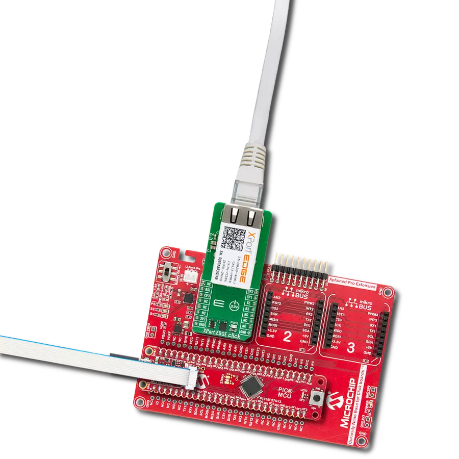
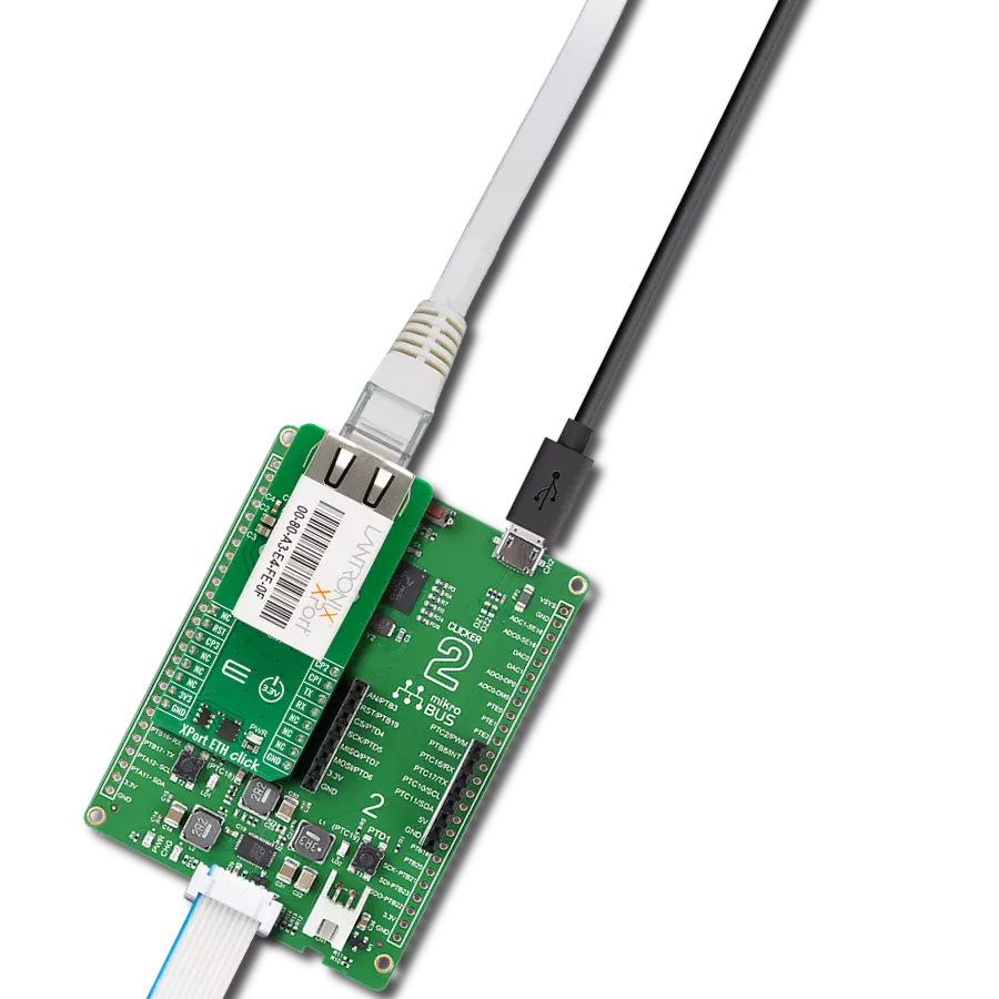
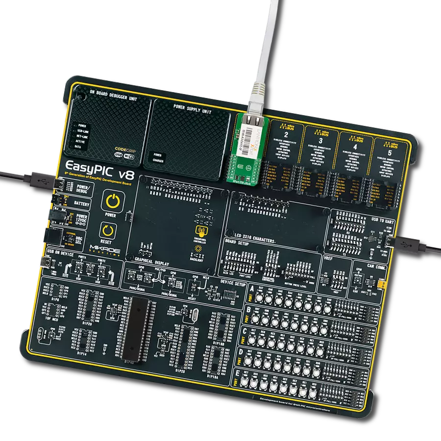
XPort EDGE Click 基于 Lantronix 的 XPE200100S 模块,采用与原始 XPort 系列相同的紧凑封装,提供新一代有线以太网网关和嵌入式设备服务器功能。该板集成 XPort EDGE 平台与 Percepxion™ 云端物联网边缘解决方案,旨在为工业和物联网应用提供安全、可靠、可管理的以太网连接。板载集成 RJ45 接口含磁性器件,支持符合 IEEE 802.3 标准的 10/100 Mbps 以太网通信,具备 HP Auto-MDIX 自动交叉检测及自动协商能力,支持全双工与半双工模式,所有功能均封装于标准以太网接口中。模块支持多种先进网络协议,包括 IPv4/IPv6、TCP/IP、UDP/IP、DHCP、BOOTP、ARP、ICMP、Auto-IP、DNS、SNMP v1/v2、Telnet 和 HTTP,适用于多种网络应用场景。XPort EDGE Click 板内建 Lantronix 可靠的
TruPort® Serial 与 TruPort® Socket 技术,可实现串口协议的透明传输,支持多会话 TCP、UDP 及 HTTP(S) 连接,确保数据通信的安全与稳定。串口最高数据速率支持 4 Mbps,用户可通过软件进行配置。模块还预集成 Percepxion™ 平台,支持远程设备管理、实时监控及应用集成,简化本地与云端部署流程。其一大亮点是由 Lantronix Infinishield™ Security 提供支持的强大安全架构,涵盖安全启动、固件在线升级(FOTA)、基于 EAPOL 的安全网络接入、基于角色的访问控制、加密密钥与配置的数据静态保护,以及对网络服务的精细策略管理。这些内建安全机制无需额外集成即可满足现代网络安全标准。XPort EDGE Click 具备工业级稳定性、先进的网络能力与全面的设备级安全特性,为现代嵌入式系统提供
完整的以太网连接与设备管理解决方案。模块通过 UART 接口与主控设备通信,同时提供三个可配置通用 I/O 引脚(CP1、CP2、CP3),可用于流控/调制解调器控制或通用信号。此外,XPort 模块配备 8MB 闪存,用于存储固件与网页内容,支持远程管理与功能定制。如前所述,模块通过 RJ45 端口直接接入以太网,并在接口前部集成双色 LED 指示灯,用于实时显示网络连接状态。本 Click board™ 仅支持 3.3V 逻辑电压工作。如需搭配其他逻辑电压的 MCU 使用,须进行适当电平转换。该板还附带软件库,包含函数接口与示例代码,便于开发者快速上手并进行二次开发。

功能概述
开发板
Nucleo-64 搭载 STM32G474R MCU 提供了一种经济高效且灵活的平台,供开发者探索新想法并原型设计他们的项目。该板利用 STM32 微控制器的多功能性,使用户能够为他们的项目选择最佳的性能与功耗平衡。它配备了 LQFP64 封装的 STM32 微控制器,并包含了如用户 LED(同时作为 ARDUINO® 信号)、用户和复位按钮,以及 32.768kHz 晶体振荡器用于精确的计时操作等基本组件。Nucleo-64 板设计考虑到扩展性和灵活性,它特有的 ARDUINO® Uno
V3 扩展连接器和 ST morpho 扩展引脚头,提供了对 STM32 I/O 的完全访问,以实现全面的项目整合。电源供应选项灵活,支持 ST-LINK USB VBUS 或外部电源,确保在各种开发环境中的适应性。该板还配备了一个具有 USB 重枚举功能的板载 ST-LINK 调试器/编程器,简化了编程和调试过程。此外,该板设计旨在简化高级开发,它的外部 SMPS 为 Vcore 逻辑供电提供高效支持,支持 USB 设备全速或 USB SNK/UFP 全速,并内置加密功能,提升了项目的功效
和安全性。通过外部 SMPS 实验的专用连接器、 用于 ST-LINK 的 USB 连接器以及 MIPI® 调试连接器,提供了更多的硬件接口和实验可能性。开发者将通过 STM32Cube MCU Package 提供的全面免费软件库和示例得到广泛支持。这些,加上与多种集成开发环境(IDE)的兼容性,包括 IAR Embedded Workbench®、MDK-ARM 和 STM32CubeIDE,确保了流畅且高效的开发体验,使用户能够充分利用 Nucleo-64 板在他们的项目中的能力。

微控制器概述
MCU卡片 / MCU

建筑
ARM Cortex-M4
MCU 内存 (KB)
512
硅供应商
STMicroelectronics
引脚数
64
RAM (字节)
128k
你完善了我!
配件
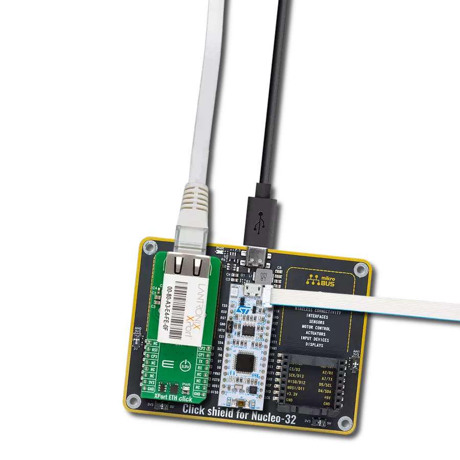
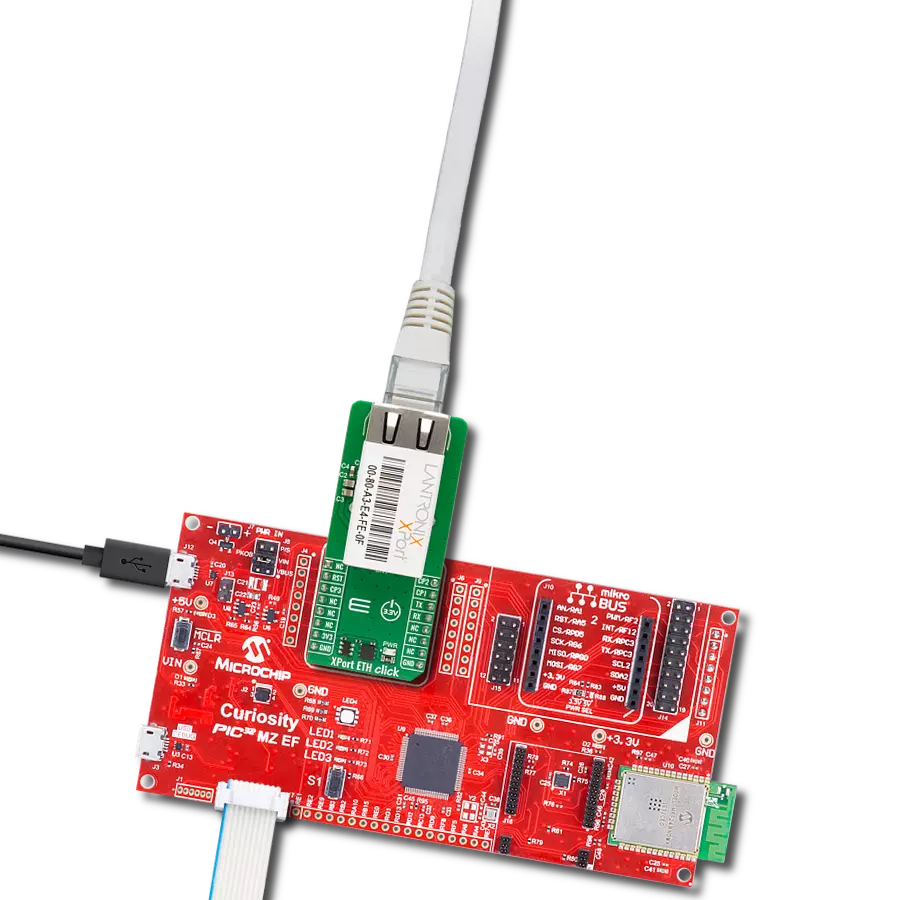
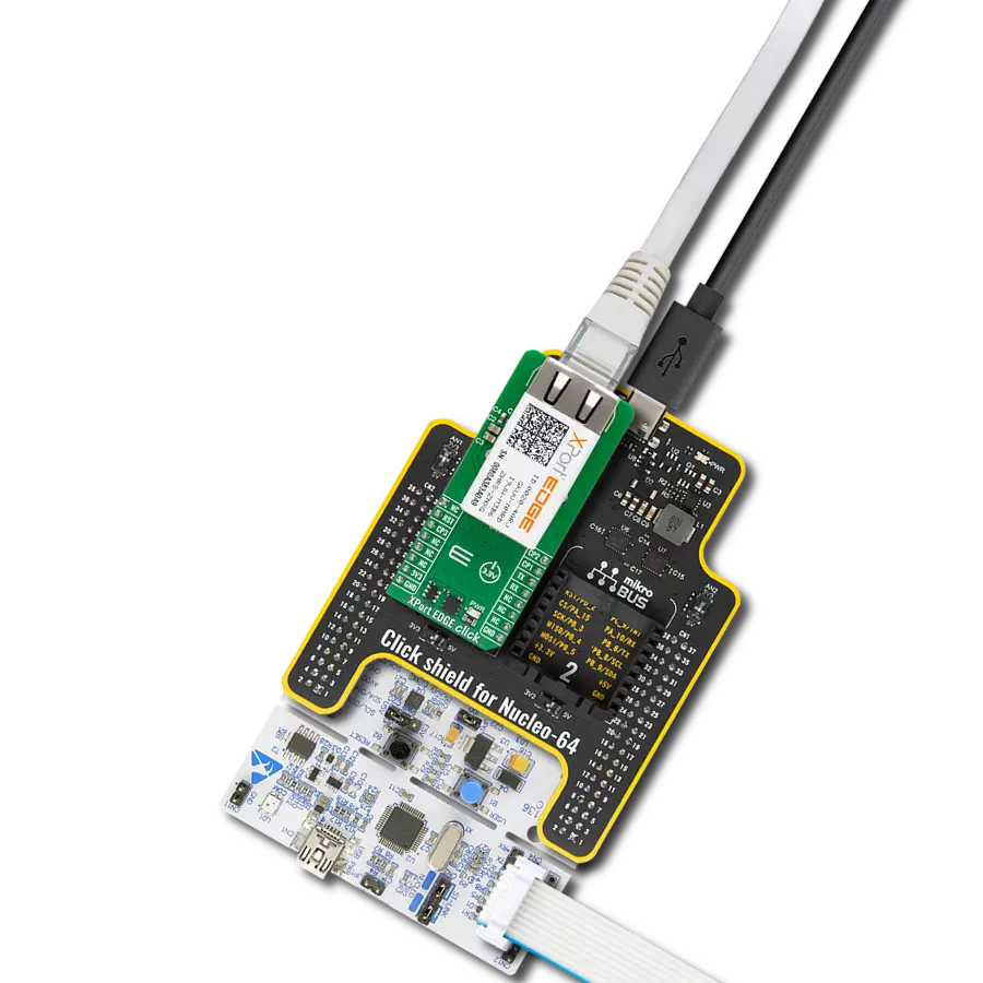
Click Shield for Nucleo-64 配备了两个专有的 mikroBUS™ 插座,使得所有的 Click board™ 设备都可以轻松地与 STM32 Nucleo-64 开发板连接。这样,Mikroe 允许其用户从不断增长的 Click boards™ 范围中添加任何功能,如 WiFi、GSM、GPS、蓝牙、ZigBee、环境传感器、LED、语音识别、电机控制、运动传感器等。您可以使用超过 1537 个 Click boards™,这些 Click boards™ 可以堆叠和集成。STM32 Nucleo-64 开发板基于 64 引脚封装的微控制器,采用 32 位 MCU,配备 ARM Cortex M4 处理器,运行速度为 84MHz,具有 512Kb Flash 和 96KB SRAM,分为两个区域,顶部区域代表 ST-Link/V2 调试器和编程器,而底部区域是一个实际的开发板。通过 USB 连接方便地控制和供电这些板子,以便直接对 Nucleo-64 开发板进行编程和高效调试,其中还需要额外的 USB 线连接到板子上的 USB 迷你接口。大多数 STM32 微控制器引脚都连接到了板子左右边缘的 IO 引脚上,然后连接到两个现有的 mikroBUS™ 插座上。该 Click Shield 还有几个开关,用于选择 mikroBUS™ 插座上模拟信号的逻辑电平和 mikroBUS™ 插座本身的逻辑电压电平。此外,用户还可以通过现有的双向电平转换器,使用任何 Click board™,无论 Click board™ 是否在 3.3V 或 5V 逻辑电压电平下运行。一旦将 STM32 Nucleo-64 开发板与我们的 Click Shield for Nucleo-64 连接,您就可以访问数百个工作于 3.3V 或 5V 逻辑电压电平的 Click boards™。

RJ45 UTP(非屏蔽双绞线)电缆是一种广泛应用于家庭和商用场景中的以太网连接线缆。该电缆两端配有 RJ45 接头,可直接连接路由器、交换机、计算机及其他网络设备。UTP 电缆由四对铜线组成,每对线缆经过扭绞处理,有效降低电磁干扰,无需额外屏蔽层。根据性能标准不同,常见类型包括 Cat5e、Cat6 和 Cat6a,分别支持不同的数据传输速率与带宽需求。RJ45 UTP 电缆广泛应用于有线网络接入、数据传输和 VoIP 系统,是实现高速网络通信的可靠选择。其即插即用的设计简化了安装流程,而双绞结构则保障了中等距离内的信号完整性。非常适合结构化布线和局域网(LAN)搭建,RJ45 UTP 电缆依然是现代网络基础设施中的关键组成部分。

使用的MCU引脚
mikroBUS™映射器
“仔细看看!”
Click board™ 原理图

一步一步来
项目组装
从选择您的开发板和Click板™开始。以Nucleo 64 with STM32G474RE MCU作为您的开发板开始。


实时跟踪您的结果
应用程序输出
1. 应用程序输出 - 在调试模式下,“应用程序输出”窗口支持实时数据监控,直接提供执行结果的可视化。请按照提供的教程正确配置环境,以确保数据正确显示。

2. UART 终端 - 使用UART Terminal通过USB to UART converter监视数据传输,实现Click board™与开发系统之间的直接通信。请根据项目需求配置波特率和其他串行设置,以确保正常运行。有关分步设置说明,请参考提供的教程。

3. Plot 输出 - Plot功能提供了一种强大的方式来可视化实时传感器数据,使趋势分析、调试和多个数据点的对比变得更加直观。要正确设置,请按照提供的教程,其中包含使用Plot功能显示Click board™读数的分步示例。在代码中使用Plot功能时,请使用以下函数:plot(insert_graph_name, variable_name);。这是一个通用格式,用户需要将“insert_graph_name”替换为实际图表名称,并将“variable_name”替换为要显示的参数。

软件支持
库描述
XPort EDGE Click 演示应用程序使用 NECTO Studio开发,确保与 mikroSDK 的开源库和工具兼容。该演示设计为即插即用,可与所有具有 mikroBUS™ 插座的 开发板、入门板和 mikromedia 板完全兼容,用于快速实现和测试。
示例描述
本示例演示了 XPort EDGE Click 板的基本功能。应用程序初始化模块,获取设备与接口信息,执行诊断命令(如 ping 指定地址),并允许用户通过 Web 浏览器访问设备的网页界面。此外,还通过 UART 终端提供 CLI(命令行接口)模式,支持进一步交互配置。
关键功能:
xportedge_cfg_setup- 初始化 Click 配置结构体为默认值。xportedge_init- 初始化 Click 板所需的全部引脚和外设。xportedge_reset_device- 通过切换 RST 引脚状态重置设备。xportedge_send_cmd- 通过 UART 接口发送命令字符串。xportedge_list_commands- 发送问号字符列出当前命令级别下的所有可用命令。
应用初始化
初始化日志记录器与 XPort EDGE Click 驱动,执行设备复位,获取设备信息,并在诊断过程中 ping 指定 IP 地址。应用程序还会检索设备的 IP 地址,用户随后可通过网页浏览器访问其 Web 界面。完成这些操作后,系统进入 CLI 模式,支持命令行方式的高级交互。
应用任务
持续监听 UART 通信,将命令和响应在 XPort EDGE Click 板与日志终端之间实时转发。用户可通过 UART 终端与设备交互,进行配置、状态查询及故障诊断等操作。
开源
代码示例
完整的应用程序代码和一个现成的项目可以通过NECTO Studio包管理器直接安装到NECTO Studio。 应用程序代码也可以在MIKROE的GitHub账户中找到。
/*!
 * @file main.c
 * @brief XPort EDGE Click Example.
 *
 * # Description
 * This example demonstrates the functionality of the XPort EDGE Click board. It initializes the module,
 * retrieves the device and interface information, performs diagnostic commands such as pinging a specific
 * address, and allows the user to access the device via its web interface. Additionally, it provides a
 * CLI (Command Line Interface) mode to UART terminal for further interaction with the device.
 *
 * The demo application is composed of two sections :
 *
 * ## Application Init
 * Initializes the logger and the XPort EDGE Click driver, performs a device reset, retrieves device
 * information, and pings the specific address in diagnostics. The application retrieves the device's IP address,
 * enabling the user to connect via a web browser and access the web interface. Finally, it enters CLI mode
 * for advanced command interactions.
 *
 * ## Application Task
 * Continuously monitors UART communication, relaying commands and responses between the XPort EDGE Click
 * board and the logger. This allows real-time interaction with the device through the UART Terminal for
 * configuration and diagnostics.
 *
 * ## Additional Function
 * - static void xportedge_clear_app_buf ( void )
 * - static void xportedge_log_app_buf ( void )
 * - static err_t xportedge_process ( xportedge_t *ctx )
 * - static err_t xportedge_read_response ( xportedge_t *ctx )
 *
 * @note
 * Ensure the XPort EDGE Click board is properly connected to the network.
 * The application uses a predefined address to test connectivity via the ping diagnostic command.
 *
 * @author Stefan Filipovic
 *
 */

#include "board.h"
#include "log.h"
#include "xportedge.h"

// Link or IP address for pinging
#define ADDRESS_TO_PING             "https://www.mikroe.com"

// Application buffer size
#define APP_BUFFER_SIZE             200
#define PROCESS_BUFFER_SIZE         100

static xportedge_t xportedge;
static log_t logger;

static uint8_t app_buf[ APP_BUFFER_SIZE ] = { 0 };
static int32_t app_buf_len = 0;

/**
 * @brief XPort EDGE clearing application buffer.
 * @details This function clears memory of application buffer and reset its length.
 * @note None.
 */
static void xportedge_clear_app_buf ( void );

/**
 * @brief XPort EDGE log application buffer.
 * @details This function logs data from application buffer to USB UART.
 * @note None.
 */
static void xportedge_log_app_buf ( void );

/**
 * @brief XPort EDGE data reading function.
 * @details This function reads data from device and concatenates data to application buffer.
 * @param[in] ctx : Click context object.
 * See #xportedge_t object definition for detailed explanation.
 * @return @li @c  0 - Read some data.
 *         @li @c -1 - Nothing is read.
 * See #err_t definition for detailed explanation.
 * @note None.
 */
static err_t xportedge_process ( xportedge_t *ctx );

/**
 * @brief XPort EDGE read response function.
 * @details This function waits for a response message, reads and displays it on the USB UART.
 * @param[in] ctx : Click context object.
 * See #xportedge_t object definition for detailed explanation.
 * @return @li @c  0 - OK response.
 *         @li @c -2 - Timeout error.
 * See #err_t definition for detailed explanation.
 * @note None.
 */
static err_t xportedge_read_response ( xportedge_t *ctx );

void application_init ( void )
{
    log_cfg_t log_cfg;  /**< Logger config object. */
    xportedge_cfg_t xportedge_cfg;  /**< Click config object. */

    /**
     * Logger initialization.
     * Default baud rate: 115200
     * Default log level: LOG_LEVEL_DEBUG
     * @note If USB_UART_RX and USB_UART_TX
     * are defined as HAL_PIN_NC, you will
     * need to define them manually for log to work.
     * See @b LOG_MAP_USB_UART macro definition for detailed explanation.
     */
    LOG_MAP_USB_UART( log_cfg );
    log_init( &logger, &log_cfg );
    log_info( &logger, " Application Init " );

    // Click initialization.
    xportedge_cfg_setup( &xportedge_cfg );
    XPORTEDGE_MAP_MIKROBUS( xportedge_cfg, MIKROBUS_1 );
    if ( UART_ERROR == xportedge_init( &xportedge, &xportedge_cfg ) )
    {
        log_error( &logger, " Communication init." );
        for ( ; ; );
    }

    log_printf( &logger, "*** Reset Device ***" );
    xportedge_reset_device ( &xportedge );
    xportedge_read_response ( &xportedge );

    log_printf( &logger, "\r\n-----------------------------\r\n" );
    log_printf( &logger, "*** Get Device Info ***" );
    xportedge_send_enter ( &xportedge );
    xportedge_read_response ( &xportedge );
    xportedge_send_cmd ( &xportedge, XPORTEDGE_CMD_STATUS );
    xportedge_read_response ( &xportedge );
    xportedge_send_cmd ( &xportedge, XPORTEDGE_CMD_STATUS_DEVICE );
    xportedge_read_response ( &xportedge );
    xportedge_send_cmd ( &xportedge, XPORTEDGE_CMD_SHOW );
    xportedge_read_response ( &xportedge );

    log_printf( &logger, "\r\n-----------------------------\r\n" );
    log_printf( &logger, "*** Go Back to Status Level ***" );
    xportedge_send_enter ( &xportedge );
    xportedge_read_response ( &xportedge );
    xportedge_send_cmd ( &xportedge, XPORTEDGE_CMD_EXIT );
    xportedge_read_response ( &xportedge );

    log_printf( &logger, "\r\n-----------------------------\r\n" );
    log_printf( &logger, "*** Get Interface Status and IP Address ***\r\n" );
    log_printf( &logger, "*** Connect to Listed IP Address Through Web Browser to Access Web Interface ***" );
    xportedge_send_enter ( &xportedge );
    xportedge_read_response ( &xportedge );
    xportedge_send_cmd ( &xportedge, XPORTEDGE_CMD_STATUS_INTERFACE_ETH0 );
    xportedge_read_response ( &xportedge );
    xportedge_send_cmd ( &xportedge, XPORTEDGE_CMD_SHOW );
    xportedge_read_response ( &xportedge );

    log_printf( &logger, "\r\n-----------------------------\r\n" );
    log_printf( &logger, "*** Go Back to Status Level ***" );
    xportedge_send_enter ( &xportedge );
    xportedge_read_response ( &xportedge );
    xportedge_send_cmd ( &xportedge, XPORTEDGE_CMD_EXIT );
    xportedge_read_response ( &xportedge );

    log_printf( &logger, "\r\n-----------------------------\r\n" );
    log_printf( &logger, "*** Ping %s ***", ( char * ) ADDRESS_TO_PING );
    xportedge_send_enter ( &xportedge );
    xportedge_read_response ( &xportedge );
    xportedge_send_cmd ( &xportedge, XPORTEDGE_CMD_STATUS_DIAGNOSTICS );
    xportedge_read_response ( &xportedge );
    xportedge_send_cmd ( &xportedge, XPORTEDGE_CMD_STATUS_DIAGNOSTICS_PING );
    xportedge_read_response ( &xportedge );
    xportedge_send_cmd ( &xportedge, XPORTEDGE_CMD_STATUS_DIAGNOSTICS_PING_HOST( ADDRESS_TO_PING ) );
    xportedge_read_response ( &xportedge );

    log_printf( &logger, "\r\n-----------------------------\r\n" );
    log_printf( &logger, "*** Go Back to ROOT Level ***" );
    xportedge_send_enter ( &xportedge );
    xportedge_read_response ( &xportedge );
    xportedge_send_cmd ( &xportedge, XPORTEDGE_CMD_EXIT );
    xportedge_read_response ( &xportedge );
    xportedge_send_cmd ( &xportedge, XPORTEDGE_CMD_EXIT );
    xportedge_read_response ( &xportedge );
    xportedge_send_cmd ( &xportedge, XPORTEDGE_CMD_EXIT );
    xportedge_read_response ( &xportedge );

    log_printf( &logger, "\r\n-----------------------------\r\n" );
    log_printf( &logger, "*** List ROOT Level Commands and Switch to CLI Terminal ***\r\n" );
    log_printf( &logger, "*** Now CLI Commands are Input from the UART Terminal ***" );
    xportedge_send_enter ( &xportedge );
    xportedge_read_response ( &xportedge );
    xportedge_list_commands ( &xportedge );
    xportedge_read_response ( &xportedge );
}

void application_task ( void )
{
    app_buf_len = uart_read( &logger.uart, app_buf, PROCESS_BUFFER_SIZE );
    if ( app_buf_len > 0 )
    {
        uart_write ( &xportedge.uart, app_buf, app_buf_len );
        xportedge_clear_app_buf ( );
    }
    app_buf_len = uart_read( &xportedge.uart, app_buf, PROCESS_BUFFER_SIZE );
    if ( app_buf_len > 0 )
    {
        uart_write ( &logger.uart, app_buf, app_buf_len );
        xportedge_clear_app_buf ( );
    }
}

int main ( void )
{
    /* Do not remove this line or clock might not be set correctly. */
    #ifdef PREINIT_SUPPORTED
    preinit();
    #endif

    application_init( );

    for ( ; ; )
    {
        application_task( );
    }

    return 0;
}

static void xportedge_clear_app_buf ( void )
{
    memset( app_buf, 0, app_buf_len );
    app_buf_len = 0;
}

static void xportedge_log_app_buf ( void )
{
    for ( int32_t buf_cnt = 0; buf_cnt < app_buf_len; buf_cnt++ )
    {
        log_printf( &logger, "%c", app_buf[ buf_cnt ] );
    }
}

static err_t xportedge_process ( xportedge_t *ctx )
{
    uint8_t rx_buf[ PROCESS_BUFFER_SIZE ] = { 0 };
    int32_t overflow_bytes = 0;
    int32_t rx_cnt = 0;
    int32_t rx_size = xportedge_generic_read( ctx, rx_buf, PROCESS_BUFFER_SIZE );
    if ( ( rx_size > 0 ) && ( rx_size <= APP_BUFFER_SIZE ) )
    {
        if ( ( app_buf_len + rx_size ) > APP_BUFFER_SIZE )
        {
            overflow_bytes = ( app_buf_len + rx_size ) - APP_BUFFER_SIZE;
            app_buf_len = APP_BUFFER_SIZE - rx_size;
            for ( int32_t buf_cnt = 0; buf_cnt < overflow_bytes; buf_cnt++ )
            {
                log_printf( &logger, "%c", app_buf[ buf_cnt ] );
            }
            memmove ( app_buf, &app_buf[ overflow_bytes ], app_buf_len );
            memset ( &app_buf[ app_buf_len ], 0, overflow_bytes );
        }
        for ( rx_cnt = 0; rx_cnt < rx_size; rx_cnt++ )
        {
            if ( rx_buf[ rx_cnt ] )
            {
                app_buf[ app_buf_len++ ] = rx_buf[ rx_cnt ];
            }
        }
        return XPORTEDGE_OK;
    }
    return XPORTEDGE_ERROR;
}

static err_t xportedge_read_response ( xportedge_t *ctx )
{
    uint32_t timeout_cnt = 0;
    uint32_t timeout = 30000;
    while ( 0 == strstr( app_buf, XPORTEDGE_CMD_TERMINAL ) )
    {
        xportedge_clear_app_buf ( );
        xportedge_process( ctx );
        xportedge_log_app_buf ( );
        if ( timeout_cnt++ > timeout )
        {
            return XPORTEDGE_ERROR_TIMEOUT;
        }
        Delay_ms ( 1 );
    }
    timeout_cnt = 0;
    timeout = 100;
    xportedge_clear_app_buf ( );
    while ( timeout_cnt++ < timeout )
    {
        if ( XPORTEDGE_OK == xportedge_process( ctx ) )
        {
            timeout_cnt = 0;
        }
        xportedge_log_app_buf ( );
        xportedge_clear_app_buf ( );
        Delay_ms ( 1 );
    }
    return XPORTEDGE_OK;
}

// ------------------------------------------------------------------------ END
额外支持
资源
类别:Ethernet