使用CP2110和STM32L496AG简化USB与UART设备之间的数据传输
瞬间完成从USB到UART的转换!
已发布 7月 22, 2025
点击板
USB UART 5 Click
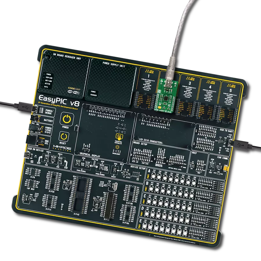
开发板
Discovery kit with STM32L496AG MCU
编译器
NECTO Studio
微控制器单元
STM32L496AG
通过 USB 转 UART 魔术革新您的数据通信项目 – 这是一种紧凑高效的解决方案,能够快速且无缝地连接您的设备。
A
A
硬件概览
它是如何工作的?
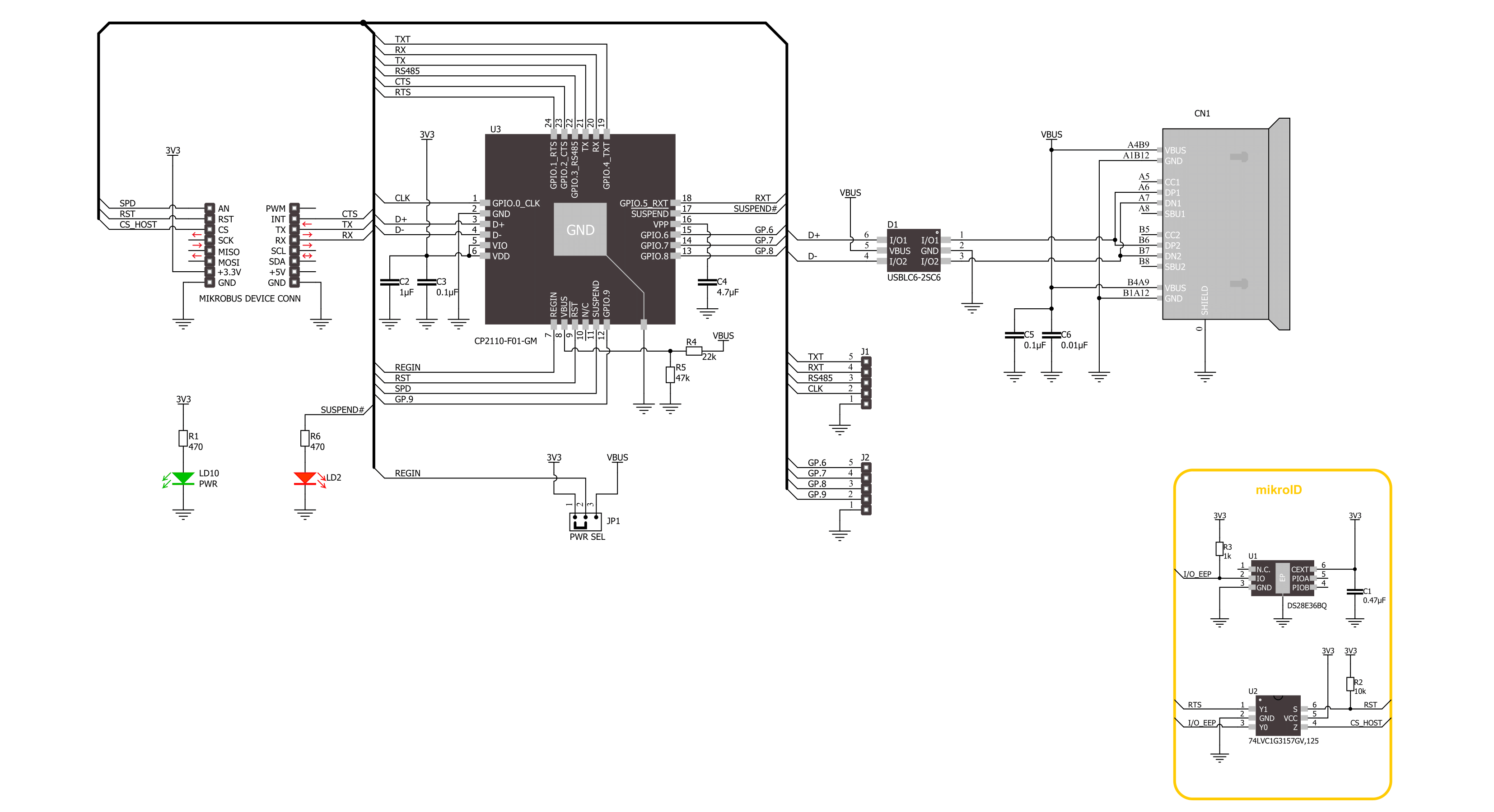
USB UART 5 Click 基于 CP2110,这是一款来自 Silicon Labs 的单芯片 HID USB 到 UART 桥接控制器。CP2110 中的 USB 功能控制器是符合 USB 2.0 标准的全速设备,集成了 USB 收发器、一次性可编程 ROM 和异步串行数据总线 (UART),集成在一个紧凑的封装中。CP2110 的 UART 功能包括支持 300 到 1Mbps 的波特率、硬件流控制、RS-485 支持以及用户定义的用于状态和控制信息的 GPIO 信号。USB 功能控制器管理 USB 和 UART 之间的所有数据传输、USB 主控制器生成的命令请求以及用于控制 UART 和 GPIO 引脚功能的命令。CP2110 使用标准的 USB HID 设备类,大多数操作系统原生支
持。此设备无需安装自定义驱动程序。此外,CP2110 还支持用于电源管理目的的 USB 挂起和恢复模式。当在 mikroBUS™ 插座的 SPD 引脚上检测到挂起信号时,CP2110 进入挂起模式。进入挂起模式时,SPD 信号被断言,但在复位条件(RST 引脚)之后,直到 USB 枚举期间设备配置完成,也可以断言 SPD 信号。SPD 引脚在设备处于挂起状态时检测到高电平逻辑,在设备处于正常模式时检测到低电平逻辑,这也通过标记为 CONNECTED 的红色 LED 进行视觉指示。此 Click board™ 还具有 8 个 GPIO 信号,位于未填充的引脚排上,用户定义用于状态和控制信息。四个 GPIO 信号支持备用功能,
包括从 24MHz 到 47kHz 的可配置时钟输出 (CLK)、RS-485 收发器控制以及 TX 和 RX LED 切换功能。此外,由于 CP2110 能够在 USB 总线电压的帮助下通过内部稳压器为其所有部分提供足够的电源,USB UART 5 Click 可以在 USB 供电配置中工作。要选择这种工作模式,必须将跳线 PWR SEL 切换到标记为 VBUS 的位置。此 Click board™ 只能在 3.3V 逻辑电压水平下运行。在使用具有不同逻辑电平的 MCU 之前,板必须进行适当的逻辑电压电平转换。此外,该 Click board™ 配备了包含易于使用的函数和示例代码的库,可作为进一步开发的参考。

功能概述
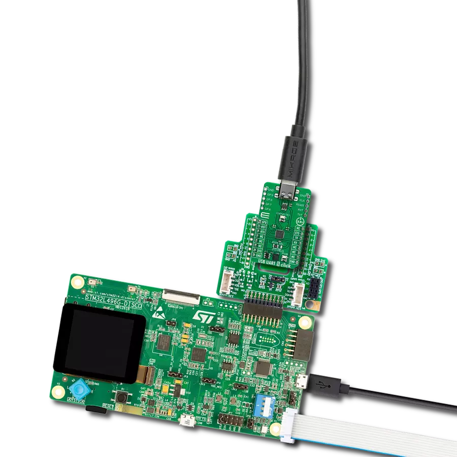
开发板
32L496GDISCOVERY Discovery 套件是一款功能全面的演示和开发平台,专为搭载 Arm® Cortex®-M4 内核的 STM32L496AG 微控制器设计。该套件适用于需要在高性能、先进图形处理和超低功耗之间取得平衡的应用,支持无缝原型开发,适用于各种嵌入式解决方案。STM32L496AG 采用创新的节能架构,集成
了扩展 RAM 和 Chrom-ART 图形加速器,在提升图形性能的同时保持低功耗,使其特别适用于音频处理、图形用户界面和实时数据采集等对能效要求较高的应用。为了简化开发流程,该开发板配备了板载 ST-LINK/V2-1 调试器/编程器,提供即插即用的调试和编程体验,使用户无需额外硬件即可轻松加载、调
试和测试应用程序。凭借低功耗特性、增强的内存能力以及内置调试工具,32L496GDISCOVERY 套件是开发先进嵌入式系统、实现高效能解决方案的理想选择。

微控制器概述
MCU卡片 / MCU

建筑
ARM Cortex-M4
MCU 内存 (KB)
1024
硅供应商
STMicroelectronics
引脚数
169
RAM (字节)
327680
使用的MCU引脚
mikroBUS™映射器
“仔细看看!”
Click board™ 原理图
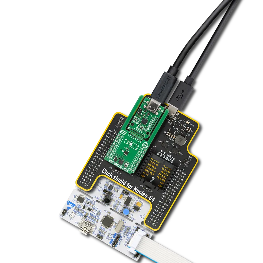
一步一步来
项目组装

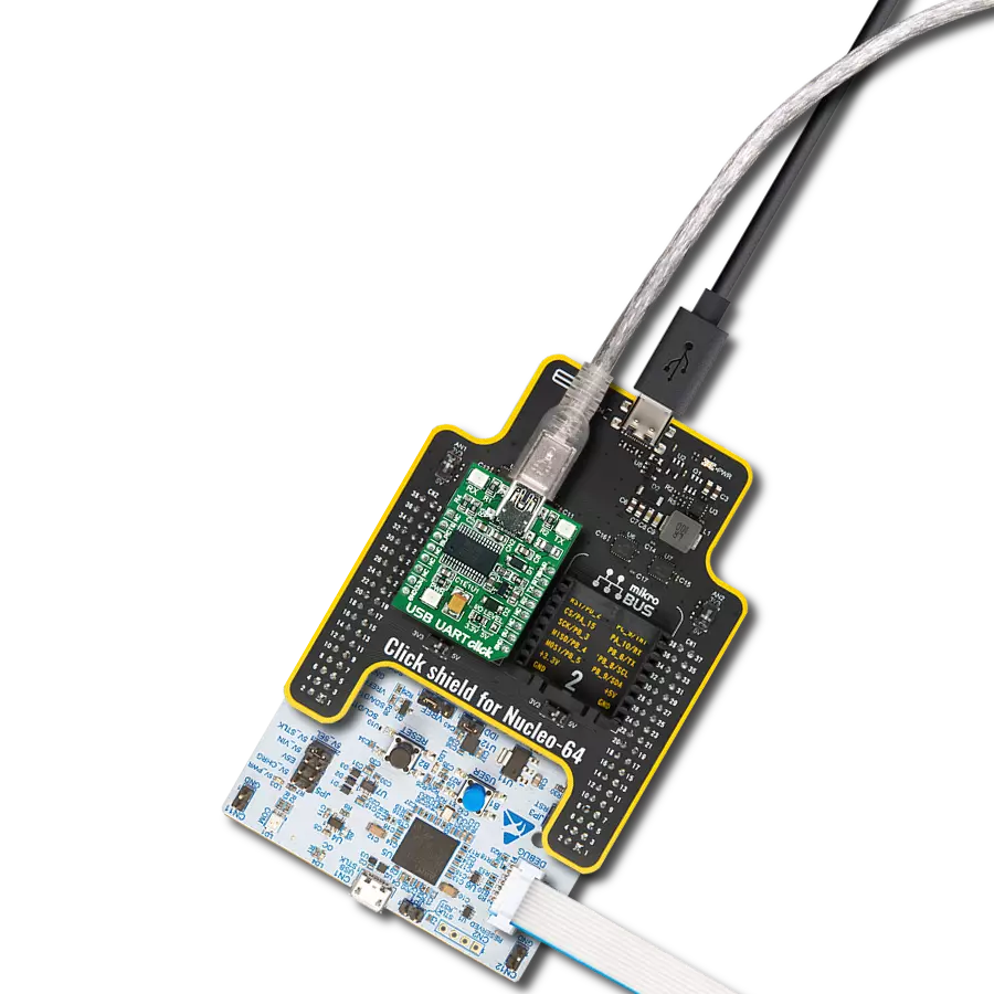
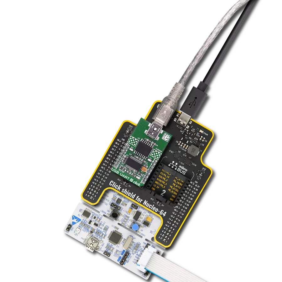
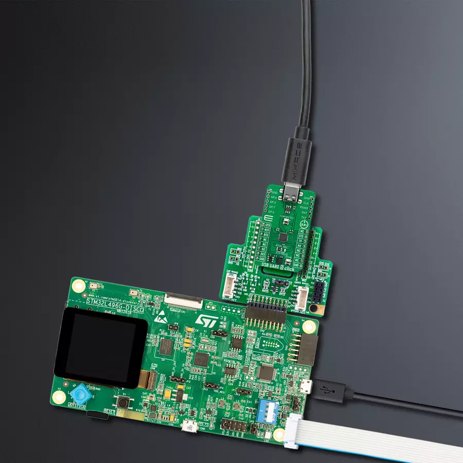
从选择您的开发板和Click板™开始。以Discovery kit with STM32L496AG MCU作为您的开发板开始。


软件支持
库描述
该库包含 USB UART 5 Click 驱动程序的 API。
关键功能:
usbuart5_generic_write- USB UART 5 数据写入功能usbuart5_generic_read- USB UART 5 数据读取功能usbuart5_reset_device- USB UART 5 重置设备功能
开源
代码示例
完整的应用程序代码和一个现成的项目可以通过NECTO Studio包管理器直接安装到NECTO Studio。 应用程序代码也可以在MIKROE的GitHub账户中找到。
/*!
 * @file main.c
 * @brief USB UART 5 Click Example.
 *
 * # Description
 * This example reads and processes data from USB UART 5 Click board™.
 * The library initializes and defines the UART bus drivers
 * to transmit or receive data.
 *
 * The demo application is composed of two sections :
 *
 * ## Application Init
 * Initializes driver, wake-up module, and performs the default configuration.
 *
 * ## Application Task
 * Any data which the host PC sends via HidUartExample
 * will be sent over USB to the Click board and then it will be read and
 * echoed back by the MCU to the PC where the terminal program will display it.
 * Results are being sent to the UART Terminal, where you can track their changes.
 *
 * @note
 * Make sure to download and install
 * CP2110/4 Software package for Windows/Mac/Linux on the host PC.
 *
 * @author Nenad Filipovic
 *
 */

#include "board.h"
#include "log.h"
#include "usbuart5.h"

static usbuart5_t usbuart5;
static log_t logger;

void application_init ( void )
{
    log_cfg_t log_cfg;  /**< Logger config object. */
    usbuart5_cfg_t usbuart5_cfg;  /**< Click config object. */

    /**
     * Logger initialization.
     * Default baud rate: 115200
     * Default log level: LOG_LEVEL_DEBUG
     * @note If USB_UART_RX and USB_UART_TX
     * are defined as HAL_PIN_NC, you will
     * need to define them manually for log to work.
     * See @b LOG_MAP_USB_UART macro definition for detailed explanation.
     */
    LOG_MAP_USB_UART( log_cfg );
    log_init( &logger, &log_cfg );
    log_info( &logger, " Application Init " );

    // Click initialization.
    usbuart5_cfg_setup( &usbuart5_cfg );
    USBUART5_MAP_MIKROBUS( usbuart5_cfg, MIKROBUS_1 );
    if ( UART_ERROR == usbuart5_init( &usbuart5, &usbuart5_cfg ) )
    {
        log_error( &logger, " Communication init." );
        for ( ; ; );
    }

    usbuart5_default_cfg ( &usbuart5 );
    log_info( &logger, " Application Task " );
}

void application_task ( void )
{
    char rx_data = 0;
    if ( usbuart5_generic_read ( &usbuart5, &rx_data, 1 ) )
    {
        if ( usbuart5_generic_write ( &usbuart5, &rx_data, 1 ) )
        {
            log_printf( &logger, "%c", rx_data );
        }
    }
}

int main ( void )
{
    /* Do not remove this line or clock might not be set correctly. */
    #ifdef PREINIT_SUPPORTED
    preinit();
    #endif

    application_init( );

    for ( ; ; )
    {
        application_task( );
    }

    return 0;
}

// ------------------------------------------------------------------------ END
额外支持
资源
类别:通用串行总线