体验我们使用DAC161S997和STM32L496AG的4-20mA电流环解决方案的高效性
提升您的过程自动化
已发布 7月 22, 2025
点击板
4-20mA T 2 Click
开发板
Discovery kit with STM32L496AG MCU
编译器
NECTO Studio
微控制器单元
STM32L496AG
体验我们先进的模拟电流环路发射器带来的精确信号传输,实现与各种工业应用的无缝连接和兼容性。
A
A
硬件概览
它是如何工作的?
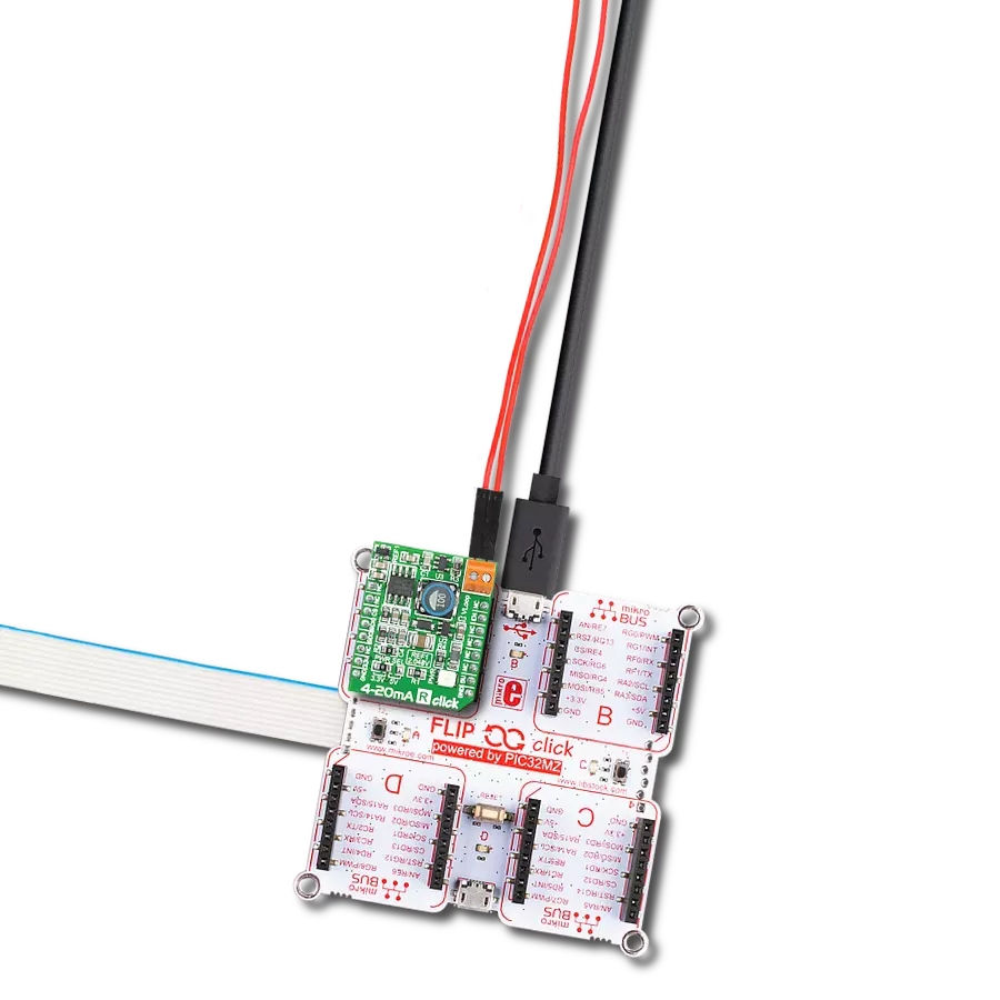
4-20mA T 2 Click 基于 DAC161S997,这是一款来自德州仪器的低功耗 16 位 ΣΔ 数模转换器 (DAC),实现为 ΣΔ 调制器。除了 ΣΔ DAC,DAC161S997 还包含一个内部超低功耗电压参考和一个内部振荡器,以减少紧凑环路供电应用中的功耗和组件数量。这种架构中,DAC 的输出电流代表过滤调制器输出的放大副本,确保了出色的线性性能,同时最大限度地降低了设备的功耗。除了通过 LOOP 端子的工业标准 4-20 mA 电流环路,DAC161S997 还可以通过板载 HART TX 端
子简单地接口到高速寻址远程传感器 (HART) 调制器。这允许将 FSK 调制的数字数据注入 4-20mA 电流环路。此 Click board™ 使用 4 线 SPI 串行接口与 MCU 通信,最大频率为 10MHz,用于数据传输和 DAC 功能配置。DAC161S997 支持 SPI 协议的模式 0 和模式 3。4-20mA T 2 Click 具有附加功能,作为中断,可通过 mikroBUS™ 插座的 ERR 引脚提供环路错误检测/报告功能。默认情况下,DAC161S997 检测并报告几种类型的错误:环路错误、SPI 超时错误(通道错误)、帧错
误和报警电流。如果发生故障情况或在初始启动序列期间,DAC161S997 将在上部或下部错误电流带中输出电流。通过板载跳线 ERRL SEL 的适当位置,用户可以选择错误电流带,而错误电流值通过 SPI 接口可编程。此 Click board™ 只能在 3.3V 逻辑电压水平下运行。在使用具有不同逻辑电平的 MCU 之前,板必须进行适当的逻辑电压电平转换。此外,该 Click board™ 配备了包含易于使用的函数和示例代码的库,可作为进一步开发的参考。

功能概述
开发板
32L496GDISCOVERY Discovery 套件是一款功能全面的演示和开发平台,专为搭载 Arm® Cortex®-M4 内核的 STM32L496AG 微控制器设计。该套件适用于需要在高性能、先进图形处理和超低功耗之间取得平衡的应用,支持无缝原型开发,适用于各种嵌入式解决方案。STM32L496AG 采用创新的节能架构,集成
了扩展 RAM 和 Chrom-ART 图形加速器,在提升图形性能的同时保持低功耗,使其特别适用于音频处理、图形用户界面和实时数据采集等对能效要求较高的应用。为了简化开发流程,该开发板配备了板载 ST-LINK/V2-1 调试器/编程器,提供即插即用的调试和编程体验,使用户无需额外硬件即可轻松加载、调
试和测试应用程序。凭借低功耗特性、增强的内存能力以及内置调试工具,32L496GDISCOVERY 套件是开发先进嵌入式系统、实现高效能解决方案的理想选择。

微控制器概述
MCU卡片 / MCU

建筑
ARM Cortex-M4
MCU 内存 (KB)
1024
硅供应商
STMicroelectronics
引脚数
169
RAM (字节)
327680
使用的MCU引脚
mikroBUS™映射器
“仔细看看!”
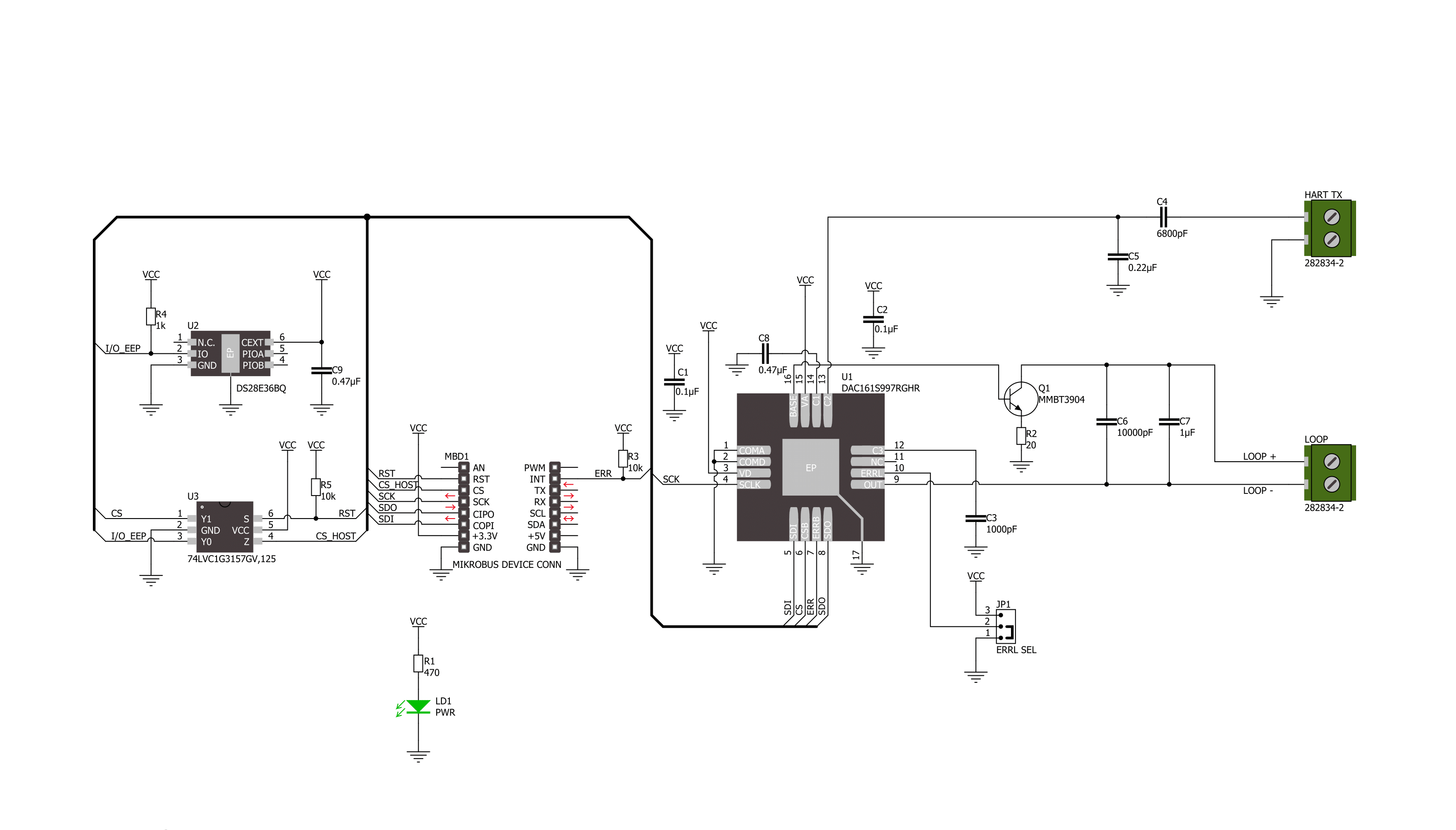
Click board™ 原理图
一步一步来
项目组装

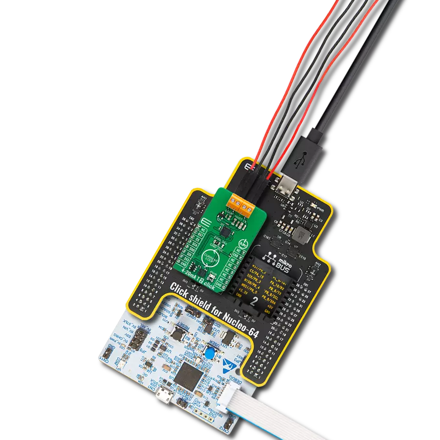
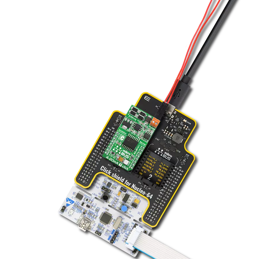
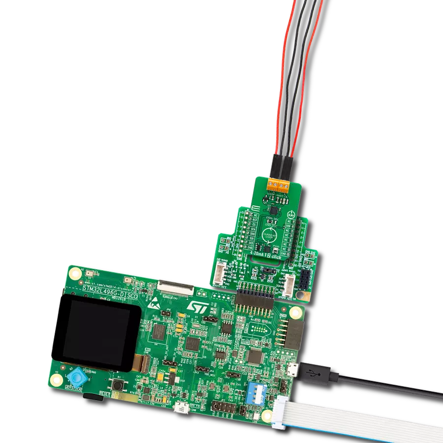
从选择您的开发板和Click板™开始。以Discovery kit with STM32L496AG MCU作为您的开发板开始。


实时跟踪您的结果
应用程序输出
1. 应用程序输出 - 在调试模式下,“应用程序输出”窗口支持实时数据监控,直接提供执行结果的可视化。请按照提供的教程正确配置环境,以确保数据正确显示。

2. UART 终端 - 使用UART Terminal通过USB to UART converter监视数据传输,实现Click board™与开发系统之间的直接通信。请根据项目需求配置波特率和其他串行设置,以确保正常运行。有关分步设置说明,请参考提供的教程。

3. Plot 输出 - Plot功能提供了一种强大的方式来可视化实时传感器数据,使趋势分析、调试和多个数据点的对比变得更加直观。要正确设置,请按照提供的教程,其中包含使用Plot功能显示Click board™读数的分步示例。在代码中使用Plot功能时,请使用以下函数:plot(insert_graph_name, variable_name);。这是一个通用格式,用户需要将“insert_graph_name”替换为实际图表名称,并将“variable_name”替换为要显示的参数。

软件支持
库描述
该库包含 4-20mA T 2 Click 驱动程序的 API。
关键功能:
c420mat2_set_output_current- 4-20mA T 2 设置输出电流功能c420mat2_get_status- 4-20mA T 2 获取状态功能c420mat2_set_lower_limit- 4-20mA T 2 设置下限功能
开源
代码示例
完整的应用程序代码和一个现成的项目可以通过NECTO Studio包管理器直接安装到NECTO Studio。 应用程序代码也可以在MIKROE的GitHub账户中找到。
/*!
 * @file main.c
 * @brief 4-20mA T 2 Click example
 *
 * # Description
 * This example demonstrates the use of 4-20mA T 2 Click board™.
 * This driver provides functions to configure
 * analog output current transfer over an industry standard 4-20mA current loop.
 *
 * The demo application is composed of two sections :
 *
 * ## Application Init
 * Initialization of SPI module and log UART.
 * After driver initialization, default settings turn on the device.
 *
 * ## Application Task
 * This example demonstrates the use of the 4-20mA T 2 Click board™.
 * This example periodically changes the analog output current transfer
 * from 4mA to 20mA and display status every 5 seconds.
 * Results are being sent to the UART Terminal, where you can track their changes.
 *
 * @author Nenad Filipovic
 *
 */

#include "board.h"
#include "log.h"
#include "c420mat2.h"

static c420mat2_t c420mat2;
static log_t logger;
static c420mat2_status_t status;

void display_status ( void )
{
    log_printf( &logger, " Status: \r\n" );
    if ( C420MAT2_STATUS_ERROR == status.ferr_sts )
    {
        log_printf( &logger, " - A frame error has occurred.\r\n" );
    }
    else
    {
        log_printf( &logger, " - No frame error occurred.\r\n" );
    }

    if ( C420MAT2_STATUS_ERROR == status.spi_timeout_err )
    {
        log_printf( &logger, " - The SPI interface has not received a valid command.\r\n" );
    }
    else
    {
        log_printf( &logger, " - The SPI interface has received a valid command.\r\n" );
    }

    if ( C420MAT2_STATUS_ERROR == status.loop_sts )
    {
        log_printf( &logger, " - A status loop error has occurred.\r\n" );
    }
    else
    {
        log_printf( &logger, " - No status loop error has occurred.\r\n" );
    }

    if ( C420MAT2_STATUS_ERROR == status.curr_loop_sts )
    {
        log_printf( &logger, " - A current loop error is occurring.\r\n" );
    }
    else
    {
        log_printf( &logger, " - No current loop error is occurring.\r\n" );
    }
    log_printf( &logger, " ----------------------------\r\n" );
}

void application_init ( void )
{
    log_cfg_t log_cfg;  /**< Logger config object. */
    c420mat2_cfg_t c420mat2_cfg;  /**< Click config object. */

    /**
     * Logger initialization.
     * Default baud rate: 115200
     * Default log level: LOG_LEVEL_DEBUG
     * @note If USB_UART_RX and USB_UART_TX
     * are defined as HAL_PIN_NC, you will
     * need to define them manually for log to work.
     * See @b LOG_MAP_USB_UART macro definition for detailed explanation.
     */
    LOG_MAP_USB_UART( log_cfg );
    log_init( &logger, &log_cfg );
    log_info( &logger, " Application Init " );

    // Click initialization.
    c420mat2_cfg_setup( &c420mat2_cfg );
    C420MAT2_MAP_MIKROBUS( c420mat2_cfg, MIKROBUS_1 );
    if ( SPI_MASTER_ERROR == c420mat2_init( &c420mat2, &c420mat2_cfg ) )
    {
        log_error( &logger, " Communication init." );
        for ( ; ; );
    }

    if ( C420MAT2_ERROR == c420mat2_default_cfg ( &c420mat2 ) )
    {
        log_error( &logger, " Default configuration." );
        for ( ; ; );
    }

    log_info( &logger, " Application Task " );
    log_printf( &logger, " -----------------------------\r\n" );
    Delay_ms ( 100 );
}

void application_task ( void )
{
    if ( C420MAT2_OK == c420mat2_set_output_current( &c420mat2, 4.0 ) )
    {
        log_printf( &logger, " Loop Current:  4.0 mA \r\n" );
        log_printf( &logger, " - - - - - - - - - - - - - - -\r\n" );
        if ( C420MAT2_OK == c420mat2_get_status ( &c420mat2, &status ) )
        {
            display_status( );
        }
        Delay_ms ( 1000 );
        Delay_ms ( 1000 );
        Delay_ms ( 1000 );
        Delay_ms ( 1000 );
        Delay_ms ( 1000 );
    }

    if ( C420MAT2_OK == c420mat2_set_output_current( &c420mat2, 10.0 ) )
    {
        log_printf( &logger, " Loop Current: 10.0 mA \r\n" );
        log_printf( &logger, " - - - - - - - - - - - - - - -\r\n" );
        if ( C420MAT2_OK == c420mat2_get_status ( &c420mat2, &status ) )
        {
            display_status( );
        }
        Delay_ms ( 1000 );
        Delay_ms ( 1000 );
        Delay_ms ( 1000 );
        Delay_ms ( 1000 );
        Delay_ms ( 1000 );
    }

    if ( C420MAT2_OK == c420mat2_set_output_current( &c420mat2, 15.0 ) )
    {
        log_printf( &logger, " Loop Current: 15.0 mA \r\n" );
        log_printf( &logger, " - - - - - - - - - - - - - - -\r\n" );
        if ( C420MAT2_OK == c420mat2_get_status ( &c420mat2, &status ) )
        {
            display_status( );
        }
        Delay_ms ( 1000 );
        Delay_ms ( 1000 );
        Delay_ms ( 1000 );
        Delay_ms ( 1000 );
        Delay_ms ( 1000 );
    }

    if ( C420MAT2_OK == c420mat2_set_output_current( &c420mat2, 20.0 ) )
    {
        log_printf( &logger, " Loop Current: 20.0 mA \r\n" );
        log_printf( &logger, " - - - - - - - - - - - - - - -\r\n" );
        if ( C420MAT2_OK == c420mat2_get_status ( &c420mat2, &status ) )
        {
            display_status( );
        }
        Delay_ms ( 1000 );
        Delay_ms ( 1000 );
        Delay_ms ( 1000 );
        Delay_ms ( 1000 );
        Delay_ms ( 1000 );
    }
}

int main ( void )
{
    /* Do not remove this line or clock might not be set correctly. */
    #ifdef PREINIT_SUPPORTED
    preinit();
    #endif

    application_init( );

    for ( ; ; )
    {
        application_task( );
    }

    return 0;
}

// ------------------------------------------------------------------------ END
额外支持
资源
类别:电流