使用 DWM3001 和 STM32F302VC 实现设备位置的实时精确跟踪
完全集成的UWB收发器
已发布 7月 22, 2025
点击板
UWB 3 Click
开发板
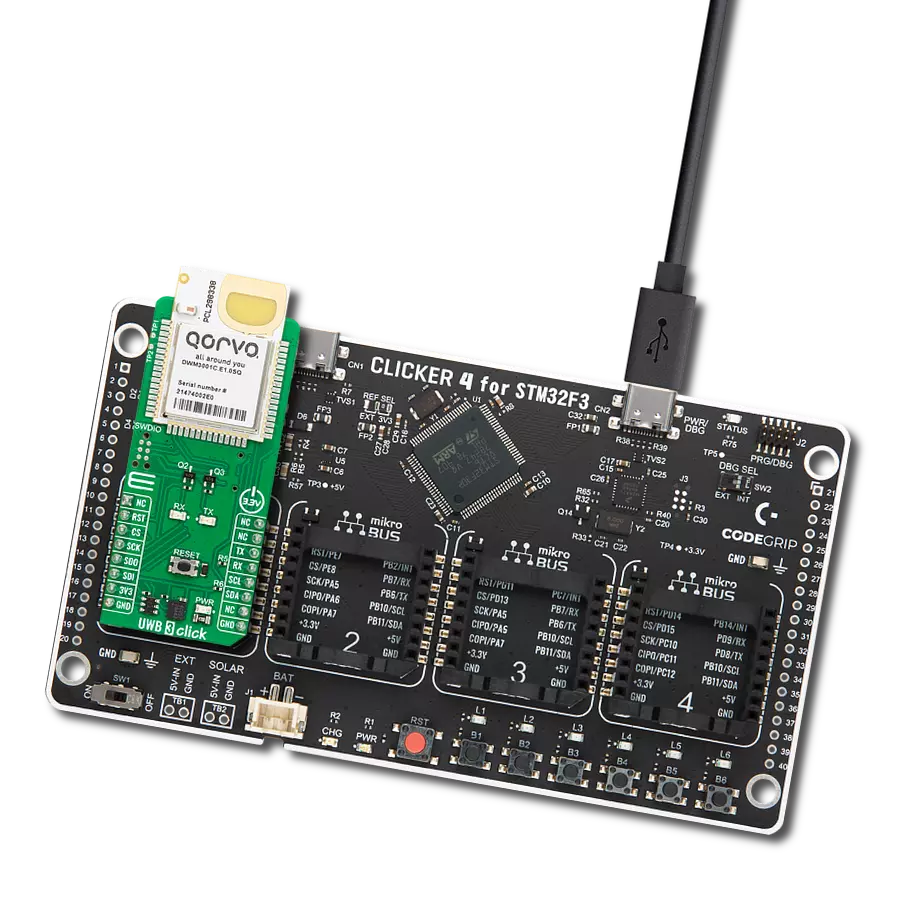
CLICKER 4 for STM32F302VCT6
编译器
NECTO Studio
微控制器单元
STM32F302VC
它对于创建需要精确位置跟踪的系统非常有用,比如实时跟踪物体或设备的位置。
A
A
硬件概览
它是如何工作的?
UWB 3 Click基于Qorvo的DWM3001,这是一款完全集成的UWB收发器模块。该模块可用于双向测距和TDoA应用。它设计符合FiRa™ PHY和MAC规范,使其能与其他符合FiRa™标准的设备实现互操作性。它支持通道5(6.5GHz)和通道9(8GHz),数据速率可达850Kbps至6.8Mbps,适用于高数据吞吐量应用,最大数据包长度为1023字节。除了平面UWB印刷天线外,还有一个蓝牙芯片天线,用于基于Nordic Cortex-M4 32位MCU的板载设备,时钟速度为64MHz,用于利用BLE无线电收发器。这个Nordic MCU是模块的核心。nRF52833具有高级的片上接口,例如NFC-A和
USB 2.0(全速12Mbps),在UWB 3 Click中以USB C形式提供。DWM3001 UWB收发器还集成了LIS12DH,一款来自STMicroelectronics的低功耗三轴线性加速度计。由于RTLS标签通常使用加速度计在标签移动时启动UWB测距,因此可以通过默认保持在最低功耗模式下来延长电池寿命。可以通过在TP1和TP2引脚上添加NFC天线来使用近场通信类型2(NFC-A)。UWB 3 Click可以使用nRF52833的标准2-Wire UART接口与主机MCU通信,常用的UART RX和TX引脚以及波特率为115200bps。还有RX和TX LED用于可视化数据流。它还可以在32MHz上使用4-Wire SPI串行接口
进行通信。除了与Nordic MCU的通信外,I2C接口还允许您读取加速度计的数据。值得注意的是,当前的模块固件不支持SPI和I2C串行接口;这些接口保留用于将来使用。您可以通过RST引脚或RESET按钮重置模块。nRF52833固件可以通过SWDIO 6针连接器进行更新。此Click board™只能使用3.3V逻辑电压电平运行。在使用具有不同逻辑电平的MCU之前,板子必须执行适当的逻辑电压电平转换。此外,该Click board™配备有一个包含易于使用的函数和示例代码的库,可用作进一步开发的参考。

功能概述
开发板
Clicker 4 for STM32F3 是一款紧凑型开发板,作为完整的解决方案而设计,可帮助用户快速构建具备独特功能的定制设备。该板搭载 STMicroelectronics 的 STM32F302VCT6 微控制器,配备四个 mikroBUS™ 插槽用于连接 Click boards™、完善的电源管理功能以及其他实用资源,是快速开发各类应用的理想平台。其核心 MCU STM32F302VCT6 基于高性能
Arm® Cortex®-M4 32 位处理器,运行频率高达 168MHz,处理能力强大,能够满足各种高复杂度任务的需求,使 Clicker 4 能灵活适应多种应用场景。除了两个 1x20 引脚排针外,板载最显著的连接特性是四个增强型 mikroBUS™ 插槽,支持接入数量庞大的 Click boards™ 生态系统,该生态每日持续扩展。Clicker 4 各功能区域标识清晰,界面直观简洁,极大
提升使用便捷性和开发效率。Clicker 4 的价值不仅在于加速原型开发与应用构建阶段,更在于其作为独立完整方案可直接集成至实际项目中,无需额外硬件修改。四角各设有直径 4.2mm(0.165")的安装孔,便于通过螺丝轻松固定。对于多数应用,只需配套一个外壳,即可将 Clicker 4 开发板转化为完整、实用且外观精美的定制系统。

微控制器概述
MCU卡片 / MCU

建筑
ARM Cortex-M4
MCU 内存 (KB)
256
硅供应商
STMicroelectronics
引脚数
100
RAM (字节)
40960
使用的MCU引脚
mikroBUS™映射器
“仔细看看!”
Click board™ 原理图

一步一步来
项目组装

从选择您的开发板和Click板™开始。以CLICKER 4 for STM32F302VCT6作为您的开发板开始。


实时跟踪您的结果
应用程序输出
1. 应用程序输出 - 在调试模式下,“应用程序输出”窗口支持实时数据监控,直接提供执行结果的可视化。请按照提供的教程正确配置环境,以确保数据正确显示。

2. UART 终端 - 使用UART Terminal通过USB to UART converter监视数据传输,实现Click board™与开发系统之间的直接通信。请根据项目需求配置波特率和其他串行设置,以确保正常运行。有关分步设置说明,请参考提供的教程。

3. Plot 输出 - Plot功能提供了一种强大的方式来可视化实时传感器数据,使趋势分析、调试和多个数据点的对比变得更加直观。要正确设置,请按照提供的教程,其中包含使用Plot功能显示Click board™读数的分步示例。在代码中使用Plot功能时,请使用以下函数:plot(insert_graph_name, variable_name);。这是一个通用格式,用户需要将“insert_graph_name”替换为实际图表名称,并将“variable_name”替换为要显示的参数。

软件支持
库描述
该库包含 UWB 3 Click 驱动程序的 API。
关键功能:
uwb3_send_cmd- 此函数向 Click 模块发送指定的命令。uwb3_send_cmd_with_parameter- 此函数向 Click 模块发送带有指定参数的命令。uwb3_reset_device- 此函数通过切换 RST 引脚状态来重置设备。
开源
代码示例
完整的应用程序代码和一个现成的项目可以通过NECTO Studio包管理器直接安装到NECTO Studio。 应用程序代码也可以在MIKROE的GitHub账户中找到。
/*!
 * @file main.c
 * @brief UWB 3 Click Example.
 *
 * # Description
 * This example demonstrates the use of an UWB 3 Click board by showing
 * the communication between the two Click boards.
 *
 * The demo application is composed of two sections :
 *
 * ## Application Init
 * Initializes the driver and configures the Click board for the selected
 * application mode.
 *
 * ## Application Task
 * Reads and processes all incoming ranging block messages and displays them
 * on the USB UART. One Click board should be configured to initiator mode and
 * the others to responder 1 or 2. The initiator Click displays the address
 * and distance of each responder nodes, while the responder Click boards displays
 * the address and distance of the initiator Click board.
 *
 * ## Additional Function
 * - static void uwb3_clear_app_buf ( void )
 * - static void uwb3_log_app_buf ( void )
 * - static err_t uwb3_process ( uwb3_t *ctx )
 * - static err_t uwb3_display_response ( uwb3_t *ctx )
 * - static err_t uwb3_parse_ranging_block ( void )
 *
 * @author Stefan Filipovic
 *
 */

#include "board.h"
#include "log.h"
#include "uwb3.h"

// Demo aplication selection macros
#define APP_INITIATOR               0
#define APP_RESPONDER_1             1
#define APP_RESPONDER_2             2
#define DEMO_APP                    APP_INITIATOR

/** INITF/RESPF parameter list and default value
 * Order    Config Param            Default value           Description
 * #1       RFRAME BPRF             4                       RFRAME BRFF set as per FiRa spec:
 *                                                          4 - SP3 SFD4Z, 6 - SP3 SFD4A
 * #2       RSTU slot duration      2400                    Duration of the slot in RSTU time units.
 *                                                          1ms = 1200 RSTU
 * #3       Block duration ms       200                     Duration of the FiRa ranging block in ms
 * #4       Round duration slots    25                      Duration of the FiRa ranging round inside
 *                                                          the block
 * #5       Ranging Round usage     2                       0 - Not used, 1 - SS-TWR, 2 - DS-TWR
 * #6       Session ID              42                      Session ID
 * #7       vupper64                01:02:03:04:05:06:07:08 Eight hexadecimal numbers, represented
 *                                                          static part of the STS in FiRa standard,
 *                                                          Hex values separated by ":"
 * #8       Multi node mode         0                       0 for unicast, 1 for multi-node configuration
 * #9       Round hopping           0                       0 for no round hopping, 1 for round hopping
 * #10      Initiator address       0                       Address of FiRa Initiator, Decimal value 0-65535
 * #11      Responder address       1                       Address of responder or set of addresses for
 *                                                          multiple responders, Decimal value 0-65535
 */
#define INITIATOR_CONFIG            "4 2400 200 25 2 42 01:02:03:04:05:06:07:08 1 0 0 1 2"
#define RESPONDER_1_CONFIG          "4 2400 200 25 2 42 01:02:03:04:05:06:07:08 1 0 0 1"
#define RESPONDER_2_CONFIG          "4 2400 200 25 2 42 01:02:03:04:05:06:07:08 1 0 0 2"

// Application buffer size
#define APP_BUFFER_SIZE             800
#define PROCESS_BUFFER_SIZE         200

static uwb3_t uwb3;
static log_t logger;

static uint8_t app_buf[ APP_BUFFER_SIZE ] = { 0 };
static int32_t app_buf_len = 0;

/**
 * @brief UWB 3 clearing application buffer.
 * @details This function clears memory of application buffer and reset its length.
 * @note None.
 */
static void uwb3_clear_app_buf ( void );

/**
 * @brief UWB 3 log application buffer.
 * @details This function logs data from application buffer to USB UART.
 * @note None.
 */
static void uwb3_log_app_buf ( void );

/**
 * @brief UWB 3 data reading function.
 * @details This function reads data from device and concatenates data to application buffer.
 * @param[in] ctx : Click context object.
 * See #uwb3_t object definition for detailed explanation.
 * @return @li @c  0 - Read some data.
 *         @li @c -1 - Nothing is read.
 * See #err_t definition for detailed explanation.
 * @note None.
 */
static err_t uwb3_process ( uwb3_t *ctx );

/**
 * @brief UWB 3 display response function.
 * @details This function reads and displays the response to previously sent command.
 * @param[in] ctx : Click context object.
 * See #uwb3_t object definition for detailed explanation.
 * @return @li @c  0 - OK response.
 *         @li @c -2 - Timeout error.
 * See #err_t definition for detailed explanation.
 */
static err_t uwb3_display_response ( uwb3_t *ctx );

/**
 * @brief UWB 3 parse ranging block function.
 * @details This function parses the ranging block results from application buffer and
 * displays it to the USB UART.
 * @return @li @c  0 - Ranging block data parsed successfully.
 *         @li @c -1 - No valid ranging block data in application buffer.
 * See #err_t definition for detailed explanation.
 */
static err_t uwb3_parse_ranging_block ( void );

void application_init ( void )
{
    log_cfg_t log_cfg;  /**< Logger config object. */
    uwb3_cfg_t uwb3_cfg;  /**< Click config object. */

    /**
     * Logger initialization.
     * Default baud rate: 115200
     * Default log level: LOG_LEVEL_DEBUG
     * @note If USB_UART_RX and USB_UART_TX
     * are defined as HAL_PIN_NC, you will
     * need to define them manually for log to work.
     * See @b LOG_MAP_USB_UART macro definition for detailed explanation.
     */
    LOG_MAP_USB_UART( log_cfg );
    log_init( &logger, &log_cfg );
    log_info( &logger, " Application Init " );

    // Click initialization.
    uwb3_cfg_setup( &uwb3_cfg );
    UWB3_MAP_MIKROBUS( uwb3_cfg, MIKROBUS_1 );
    if ( UART_ERROR == uwb3_init( &uwb3, &uwb3_cfg ) )
    {
        log_error( &logger, " Communication init." );
        for ( ; ; );
    }
    // Clear buffers
    uwb3_process( &uwb3 );
    uwb3_clear_app_buf( );

    // Switch to stop mode
    uwb3_send_cmd ( &uwb3, UWB3_CMD_STOP );
    uwb3_display_response ( &uwb3 );
    Delay_ms ( 1000 );

#if ( DEMO_APP == APP_RESPONDER_1 )
    uwb3_send_cmd_with_parameter ( &uwb3, UWB3_CMD_RESPF, RESPONDER_1_CONFIG );
    uwb3_display_response ( &uwb3 );
    log_printf( &logger, "Application Mode: Responder 1\r\n" );
#elif ( DEMO_APP == APP_RESPONDER_2 )
    uwb3_send_cmd_with_parameter ( &uwb3, UWB3_CMD_RESPF, RESPONDER_2_CONFIG );
    uwb3_display_response ( &uwb3 );
    log_printf( &logger, "Application Mode: Responder 2\r\n" );
#else
    uwb3_send_cmd_with_parameter ( &uwb3, UWB3_CMD_INITF, INITIATOR_CONFIG );
    uwb3_display_response ( &uwb3 );
    log_printf( &logger, "Application Mode: Initiator\r\n" );
#endif

    uwb3_clear_app_buf( );
    log_info( &logger, " Application Task " );
}

void application_task ( void )
{
    if ( UWB3_OK == uwb3_process( &uwb3 ) )
    {
        if ( UWB3_OK == uwb3_parse_ranging_block ( ) )
        {
            uwb3_clear_app_buf( );
        }
    }
}

int main ( void )
{
    /* Do not remove this line or clock might not be set correctly. */
    #ifdef PREINIT_SUPPORTED
    preinit();
    #endif

    application_init( );

    for ( ; ; )
    {
        application_task( );
    }

    return 0;
}

static void uwb3_clear_app_buf ( void )
{
    memset( app_buf, 0, app_buf_len );
    app_buf_len = 0;
}

static void uwb3_log_app_buf ( void )
{
    for ( int32_t buf_cnt = 0; buf_cnt < app_buf_len; buf_cnt++ )
    {
        log_printf( &logger, "%c", app_buf[ buf_cnt ] );
    }
}

static err_t uwb3_process ( uwb3_t *ctx )
{
    uint8_t rx_buf[ PROCESS_BUFFER_SIZE ] = { 0 };
    int32_t overflow_bytes = 0;
    int32_t rx_cnt = 0;
    int32_t rx_size = uwb3_generic_read( ctx, rx_buf, PROCESS_BUFFER_SIZE );
    if ( ( rx_size > 0 ) && ( rx_size <= APP_BUFFER_SIZE ) )
    {
        if ( ( app_buf_len + rx_size ) > APP_BUFFER_SIZE )
        {
            overflow_bytes = ( app_buf_len + rx_size ) - APP_BUFFER_SIZE;
            app_buf_len = APP_BUFFER_SIZE - rx_size;
            memmove ( app_buf, &app_buf[ overflow_bytes ], app_buf_len );
            memset ( &app_buf[ app_buf_len ], 0, overflow_bytes );
        }
        for ( rx_cnt = 0; rx_cnt < rx_size; rx_cnt++ )
        {
            if ( rx_buf[ rx_cnt ] )
            {
                app_buf[ app_buf_len++ ] = rx_buf[ rx_cnt ];
            }
        }
        return UWB3_OK;
    }
    return UWB3_ERROR;
}

static err_t uwb3_display_response ( uwb3_t *ctx )
{
    uint32_t timeout_cnt = 0;
    uint32_t timeout = 10000;
    uwb3_clear_app_buf( );
    uwb3_process( ctx );
    while ( ( 0 == strstr( app_buf, UWB3_RSP_OK ) ) &&
            ( 0 == strstr( app_buf, UWB3_RSP_ERROR ) ) )
    {
        uwb3_process( ctx );
        if ( timeout_cnt++ > timeout )
        {
            uwb3_clear_app_buf( );
            log_error( &logger, " Timeout!" );
            return UWB3_ERROR_TIMEOUT;
        }
        Delay_ms ( 1 );
    }
    Delay_ms ( 100 );
    uwb3_process( ctx );
    uwb3_log_app_buf ( );
    log_printf( &logger, "--------------------------\r\n" );
    return UWB3_OK;
}

static err_t uwb3_parse_ranging_block ( void )
{
    uint8_t * __generic_ptr start_block_ptr = NULL;
    uint8_t * __generic_ptr end_block_ptr = NULL;
    uint8_t * __generic_ptr results_ptr = NULL;
    start_block_ptr = &app_buf[ 0 ];
    for ( ; ; )
    {
        start_block_ptr = strstr( start_block_ptr, "\"Block\"" );
        if ( !start_block_ptr )
        {
            return UWB3_ERROR;
        }
        end_block_ptr = strstr( start_block_ptr, "\r\n" );
        if ( !end_block_ptr )
        {
            return UWB3_ERROR;
        }
        results_ptr = strstr( start_block_ptr, "\"Status\":\"Ok\"" );
        if ( results_ptr && ( ( uint32_t ) results_ptr < ( uint32_t ) end_block_ptr ) )
        {
            log_printf( &logger, "######### " );
            while ( ',' != *start_block_ptr )
            {
                log_printf( &logger, "%c", *start_block_ptr );
                start_block_ptr++;
            }
            log_printf( &logger, " #########\r\n\n" );

            while ( results_ptr && ( ( uint32_t ) results_ptr < ( uint32_t ) end_block_ptr ) )
            {
                // Display node address
                results_ptr -= 16;
                while ( ',' != *results_ptr )
                {
                    log_printf( &logger, "%c", *results_ptr );
                    results_ptr++;
                }
                log_printf( &logger, "\r\n" );
                // Display node distance
                results_ptr = strstr( results_ptr, "\"D_cm\"" );
                while ( ',' != *results_ptr )
                {
                    log_printf( &logger, "%c", *results_ptr );
                    results_ptr++;
                }
                log_printf( &logger, "\r\n\n" );
                results_ptr = strstr( results_ptr, "\"Status\":\"Ok\"" );
            }
            return UWB3_OK;
        }
        start_block_ptr = end_block_ptr;
    }
}

// ------------------------------------------------------------------------ END
额外支持
资源
类别:超宽带