使用IF-D91、IF-E97和PIC32MZ2048EFM100集成光纤通信,实现闪电般的高速数据交换
通过光纤创新改变设计
已发布 7月 22, 2025
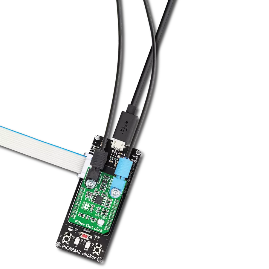
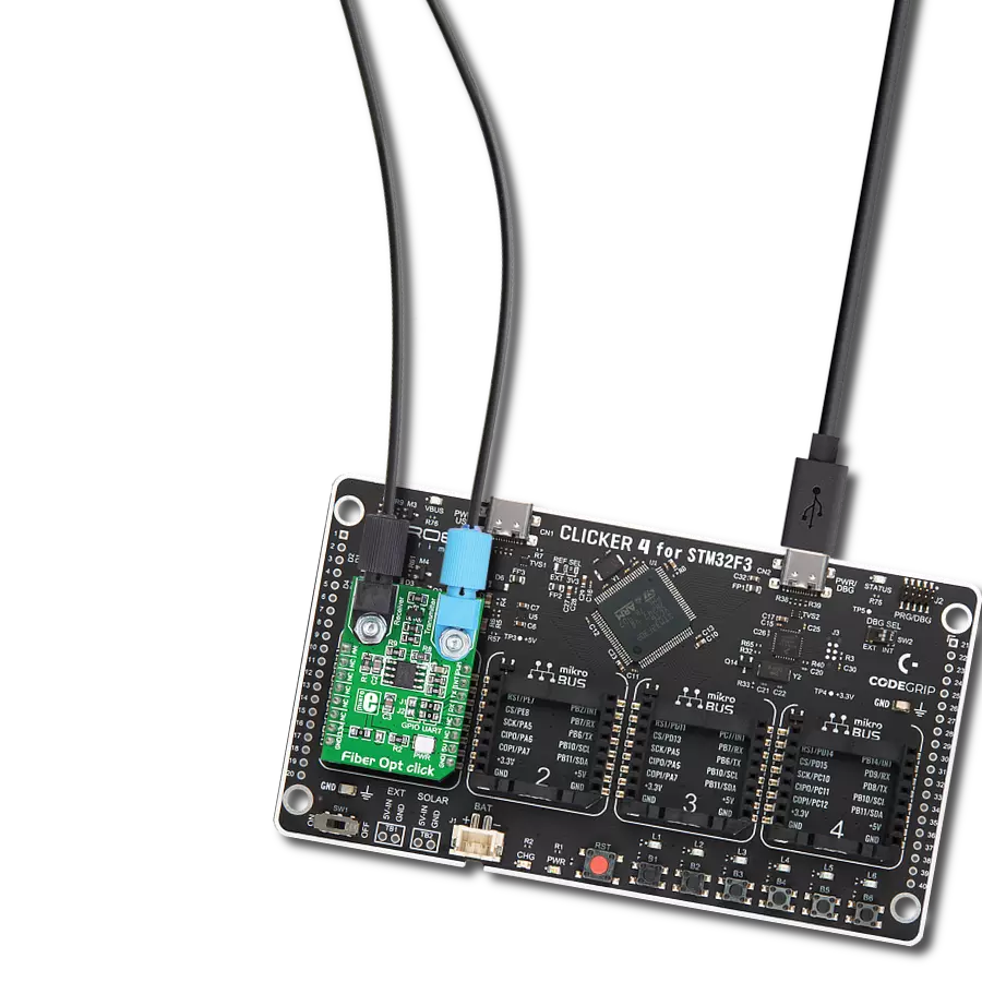
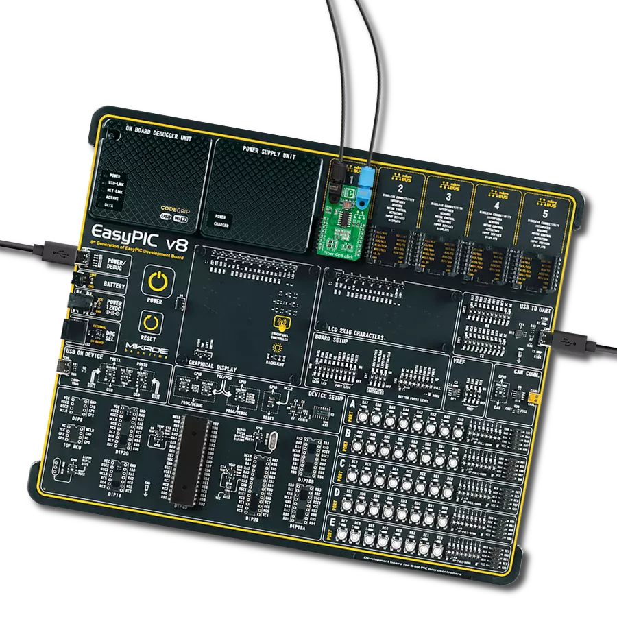
点击板
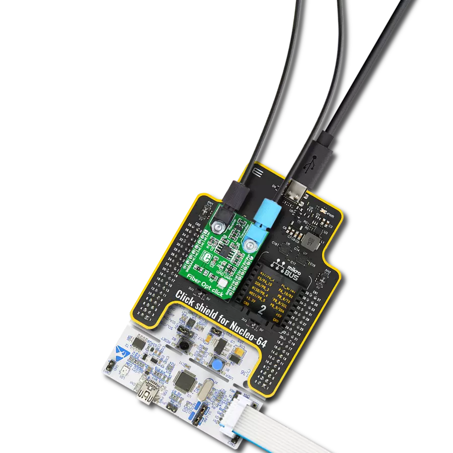
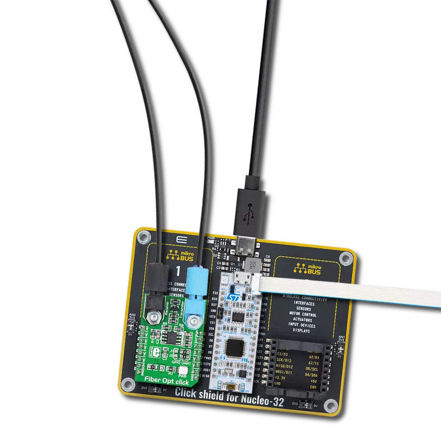
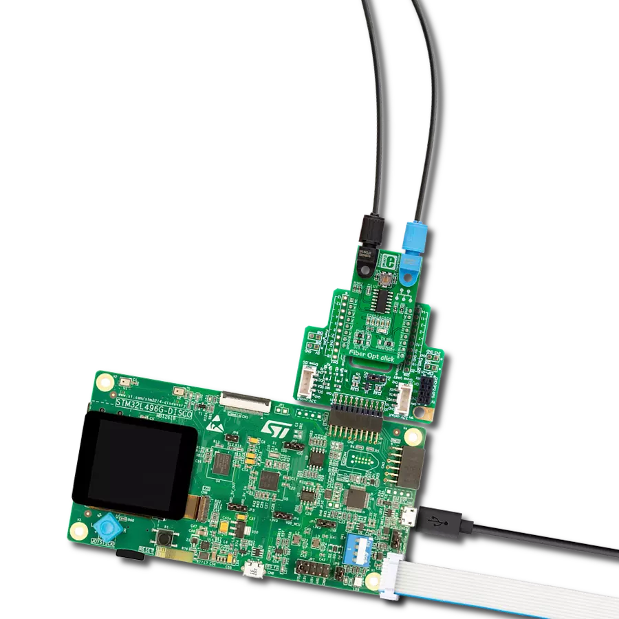
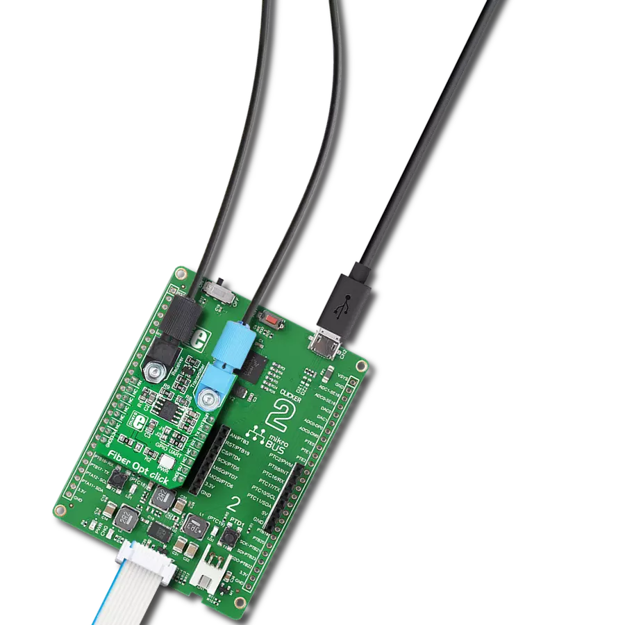
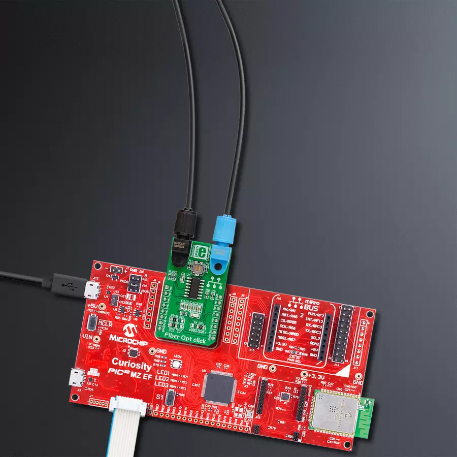
Fiber Opt click
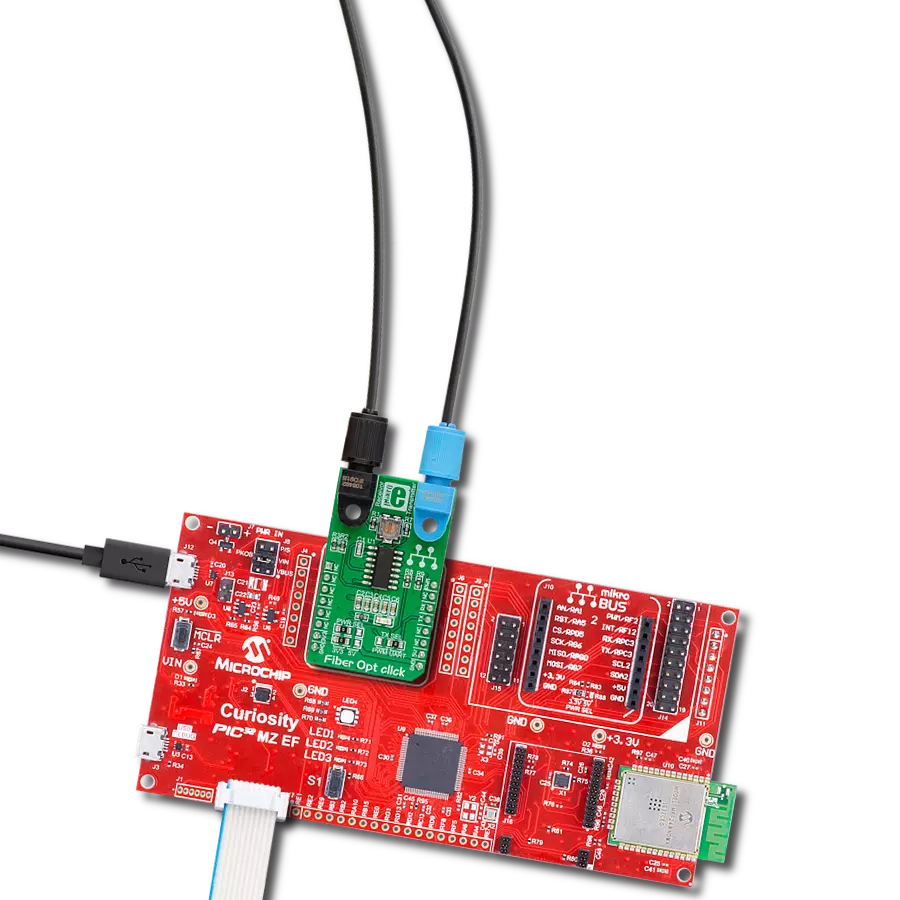
开发板
Curiosity PIC32 MZ EF
编译器
NECTO Studio
微控制器单元
PIC32MZ2048EFM100
集成高速光纤通信,建立可靠、安全的网络,以满足迅速数据交换的增长需求,同时提高整体性能和效率。
A
A
硬件概览
它是如何工作的?
Fiber Opt Click基于一颗IF-D91光纤光电二极管和一颗IF-E97光纤LED,均来自Industrial Fiber Optics公司。IF-D91是一个高速光电二极管检测器,封装在一个无连接的塑料光纤包中。其光学响应范围从400到1100纳米,与各种可见光和近红外LED和激光二极管兼容。检测器封装具有内部微透镜和精密成型的PBT外壳,确保与标准的1000微米芯2.2毫米护套塑料光纤电缆的有效光耦合,可达100Mbps的数据速率。IF-D91还可用于带宽高达70MHz
的模拟视频链路。另一个精密成型的PBT外壳,带有内部微透镜的IF-E97,是一颗高光输出的可见红色LED。外壳确保与相同标准护套塑料光纤电缆的有效光耦合。输出光谱由GaAlAs芯片产生,峰值波长为650纳米,代表了PMMA塑料光纤的最佳传输窗口。可见红光在PMMA塑料光纤中的衰减较低,有助于故障排除安装问题,并且是IF-E97实现1Mbps数据速率的主要原因。此Click board™通过 mikroBUS™插座上可选择的引脚与主机MCU
通信。可以通过TX SEL选择跳线在UART TX引脚或mikroBUS™插座的PWM引脚之间进行传输,UART默认选择。接收到的数据可在mikroBUS™插座的RX引脚上获取。此Click board™可以通过PWR SEL选择跳线选择3.3V或5V逻辑电压电平操作。这样,既能支持3.3V也能支持5V的MCU可以正确使用通信线路。此外,该Click board™配备了一个包含易于使用的功能和示例代码的库,可用作进一步开发的参考。

功能概述
开发板
Curiosity PIC32 MZ EF 开发板是一个完全集成的 32 位开发平台,特点是高性能的 PIC32MZ EF 系列(PIC32MZ2048EFM),该系列具有 2MB Flash、512KB RAM、集成的浮点单元(FPU)、加密加速器和出色的连接选项。它包括一个集成的程序员和调试器,无需额外硬件。用户可以通过 MIKROE
mikroBUS™ Click™ 适配器板扩展功能,通过 Microchip PHY 女儿板添加以太网连接功能,使用 Microchip 扩展板添加 WiFi 连接能力,并通过 Microchip 音频女儿板添加音频输入和输出功能。这些板完全集成到 PIC32 强大的软件框架 MPLAB Harmony 中,该框架提供了一个灵活且模块化的接口
来应用开发、一套丰富的互操作软件堆栈(TCP-IP、USB)和易于使用的功能。Curiosity PIC32 MZ EF 开发板提供了扩展能力,使其成为连接性、物联网和通用应用中快速原型设计的绝佳选择。

微控制器概述
MCU卡片 / MCU

建筑
PIC32
MCU 内存 (KB)
2048
硅供应商
Microchip
引脚数
100
RAM (字节)
524288
使用的MCU引脚
mikroBUS™映射器
“仔细看看!”
Click board™ 原理图

一步一步来
项目组装

从选择您的开发板和Click板™开始。以Curiosity PIC32 MZ EF作为您的开发板开始。


软件支持
库描述
这个库包含Fiber Opt Click驱动程序的API。
关键功能:
fiberopt_generic_write- 通用单写功能fiberopt_generic_read- 通用单读功能
开源
代码示例
完整的应用程序代码和一个现成的项目可以通过NECTO Studio包管理器直接安装到NECTO Studio。 应用程序代码也可以在MIKROE的GitHub账户中找到。
/*!
 * \file
 * \brief Fiber Opt Click example
 *
 * # Description
 * This example demonstrates the use of an Fiber Opt Click board by showing
 * the communication between the two Click boards.
 *
 * The demo application is composed of two sections :
 *
 * ## Application Init
 * Initalizes device and makes an initial log.
 *
 * ## Application Task
 * Depending on the selected application mode, it reads all the received data or
 * sends the desired text message with the message counter once per second.
 *
 * \author MikroE Team
 *
 */

#include "board.h"
#include "log.h"
#include "fiberopt.h"

// Comment out the line below in order to switch the application mode to receiver
#define DEMO_APP_TRANSMITTER

// Text message to send in the transmitter application mode
#define DEMO_TEXT_MESSAGE           "MIKROE - Fiber Opt Click board\r\n\0"

static fiberopt_t fiberopt;
static log_t logger;

void application_init ( void )
{
    log_cfg_t log_cfg;
    fiberopt_cfg_t cfg;

    /**
     * Logger initialization.
     * Default baud rate: 115200
     * Default log level: LOG_LEVEL_DEBUG
     * @note If USB_UART_RX and USB_UART_TX
     * are defined as HAL_PIN_NC, you will
     * need to define them manually for log to work.
     * See @b LOG_MAP_USB_UART macro definition for detailed explanation.
     */
    LOG_MAP_USB_UART( log_cfg );
    log_init( &logger, &log_cfg );
    log_info( &logger, " Application Init " );

    // Click initialization.
    fiberopt_cfg_setup( &cfg );
    FIBEROPT_MAP_MIKROBUS( cfg, MIKROBUS_1 );
    fiberopt_init( &fiberopt, &cfg );

#ifdef DEMO_APP_TRANSMITTER
    log_printf( &logger, " Application Mode: Transmitter\r\n" );
#else
    log_printf( &logger, " Application Mode: Receiver\r\n" );
#endif
    log_info( &logger, " Application Task " );
    Delay_ms ( 100 );
}

void application_task ( void )
{
#ifdef DEMO_APP_TRANSMITTER
    fiberopt_generic_write( &fiberopt, DEMO_TEXT_MESSAGE, strlen( DEMO_TEXT_MESSAGE ) );
    log_printf( &logger, "%s", ( char * ) DEMO_TEXT_MESSAGE );
    Delay_ms ( 1000 );
#else
    uint8_t rx_byte = 0;
    if ( 1 == fiberopt_generic_read( &fiberopt, &rx_byte, 1 ) )
    {
       log_printf( &logger, "%c", rx_byte );
    }
#endif
}

int main ( void )
{
    /* Do not remove this line or clock might not be set correctly. */
    #ifdef PREINIT_SUPPORTED
    preinit();
    #endif

    application_init( );

    for ( ; ; )
    {
        application_task( );
    }

    return 0;
}


// ------------------------------------------------------------------------ END
额外支持
资源
类别:光纤