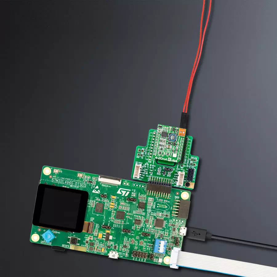
使用INA196和STM32L496AG设计一个4-20mA电流环标准的接收器
接收和解释电流信号
已发布 7月 22, 2025
点击板
4-20 mA R Click
开发板
Discovery kit with STM32L496AG MCU
编译器
NECTO Studio
微控制器单元
STM32L496AG
紧凑高效的解决方案,用于接收和监控工业系统中的电流。
A
A
硬件概览
它是如何工作的?
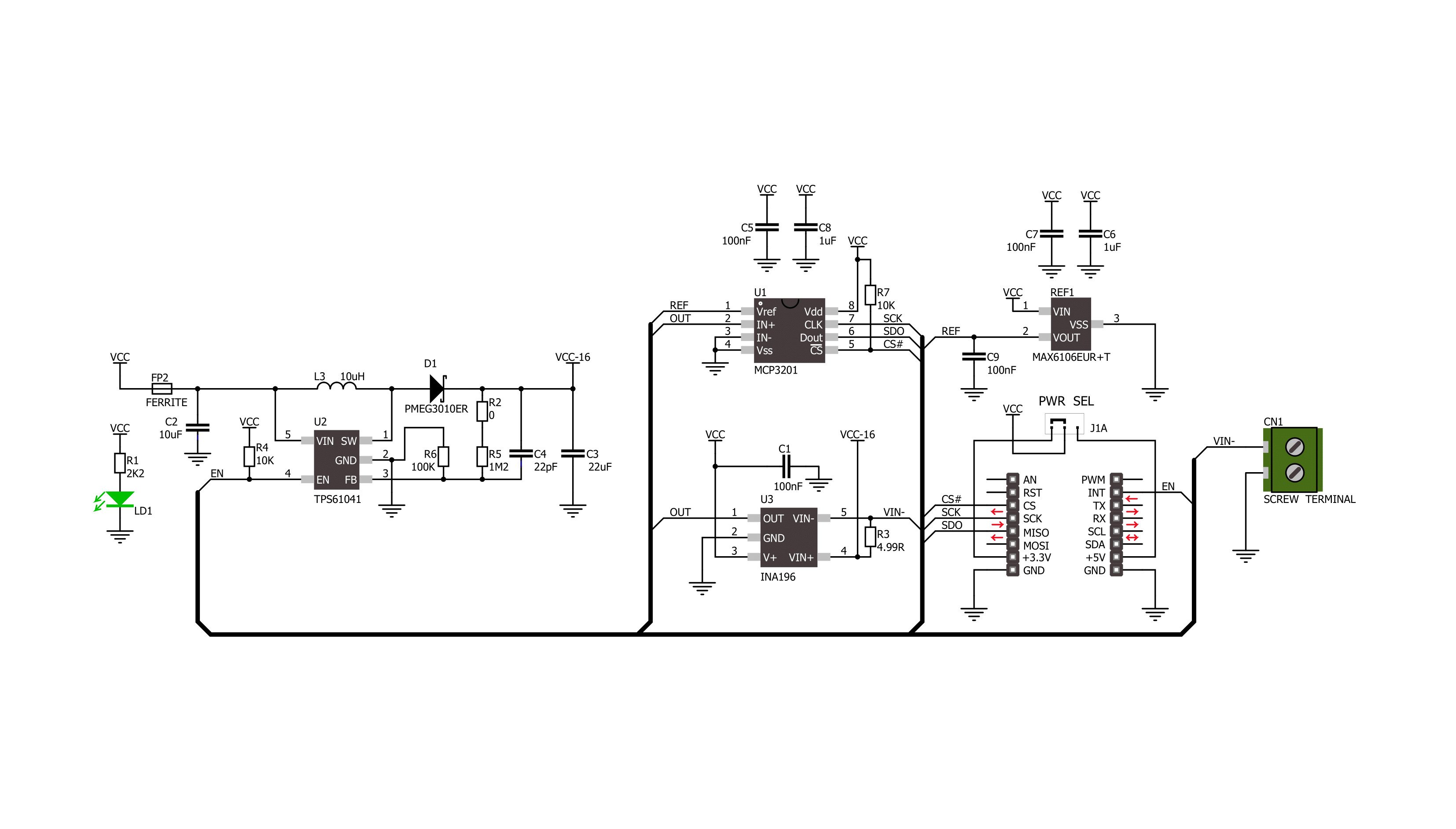
4-20mA R Click 基于 Texas Instruments 的 INA196,这是一个具有电压输出的电流分流监视器。INA196 能够在不干扰其供电电压的情况下感应跨分流器的电压降,并在电流控制环中使用 500kHz 的带宽。4-20mA R Click 接收来自兼容发射器的 4 到 20mA 的输出电流,并将其转换为低电压。此板上的传输环路电流直接来自于 INA196 分流电阻的负载 侧,通过 VLOOP 螺钉端子。INA196 供电侧的差分
输入电压来自 Texas Instruments 的 TPS61041,一个 DC/DC 升压转换器。默认配置下,它提供 16V 电压,并可以通过 mikroBUS™ 插座的 EN 引脚启用。此外,通过替换 R2 0 欧姆电阻为其他值,它也可以转换其他电压。INA196 的输出然后传递到 Microchip 的 MCP3201,一个 12 位 ADC。它通过 mikroBUS™ 插座的 SPI 串行接口与主微控制器通信,参考电压为 2.048V。ADC 的参考电压来自
Analog Devices 的 MAX6106,一个电压参考 LDO。此 Click board™ 可以通过 PWR SEL 跳线选择使用 3.3V 或 5V 的逻辑电压水平,使得 3.3V 和 5V 能力的 MCU 都能正确使用通信线路。然而,这款 Click board™ 配备了一个包含易于使用的功能和示例代码的库,可作为进一步开发的参考。

功能概述
开发板
32L496GDISCOVERY Discovery 套件是一款功能全面的演示和开发平台,专为搭载 Arm® Cortex®-M4 内核的 STM32L496AG 微控制器设计。该套件适用于需要在高性能、先进图形处理和超低功耗之间取得平衡的应用,支持无缝原型开发,适用于各种嵌入式解决方案。STM32L496AG 采用创新的节能架构,集成
了扩展 RAM 和 Chrom-ART 图形加速器,在提升图形性能的同时保持低功耗,使其特别适用于音频处理、图形用户界面和实时数据采集等对能效要求较高的应用。为了简化开发流程,该开发板配备了板载 ST-LINK/V2-1 调试器/编程器,提供即插即用的调试和编程体验,使用户无需额外硬件即可轻松加载、调
试和测试应用程序。凭借低功耗特性、增强的内存能力以及内置调试工具,32L496GDISCOVERY 套件是开发先进嵌入式系统、实现高效能解决方案的理想选择。

微控制器概述
MCU卡片 / MCU

建筑
ARM Cortex-M4
MCU 内存 (KB)
1024
硅供应商
STMicroelectronics
引脚数
169
RAM (字节)
327680
使用的MCU引脚
mikroBUS™映射器
“仔细看看!”
Click board™ 原理图
一步一步来
项目组装

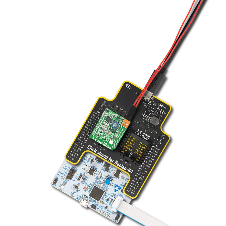
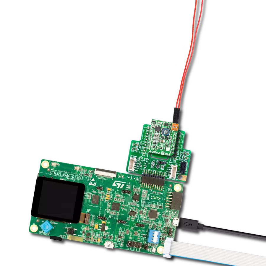
从选择您的开发板和Click板™开始。以Discovery kit with STM32L496AG MCU作为您的开发板开始。


软件支持
库描述
此库包含 4-20mA R Click 驱动程序的 API。
关键功能:
c420mar_read_data- 此函数从 SPI 数据寄存器读取 16 位电流值,然后将其规范化并转换为浮点数。
开源
代码示例
完整的应用程序代码和一个现成的项目可以通过NECTO Studio包管理器直接安装到NECTO Studio。 应用程序代码也可以在MIKROE的GitHub账户中找到。
/*!
 * \file
 * \brief 420MaR Click example
 *
 * # Description
 * This example showcases how to initialize, configure and use the 4-20 mA R Click. It is a
 * simple SPI communication module that acts as a receiver in a 4-20 current loop. The Click
 * reads current data and converts the analog signal to a digital 12-bit format.
 *
 * The demo application is composed of two sections :
 *
 * ## Application Init
 * This function initializes and configures the logger and Click modules.
 *
 * ## Application Task
 * This function reads and displays current data every half a second.
 *
 * \author MikroE Team
 *
 */
// ------------------------------------------------------------------- INCLUDES

#include "board.h"
#include "log.h"
#include "c420mar.h"

// ------------------------------------------------------------------ VARIABLES

static c420mar_t c420mar;
static log_t logger;

// ------------------------------------------------------ APPLICATION FUNCTIONS

void application_init ( )
{
    log_cfg_t log_cfg;
    c420mar_cfg_t cfg;

    /**
     * Logger initialization.
     * Default baud rate: 115200
     * Default log level: LOG_LEVEL_DEBUG
     * @note If USB_UART_RX and USB_UART_TX
     * are defined as HAL_PIN_NC, you will
     * need to define them manually for log to work.
     * See @b LOG_MAP_USB_UART macro definition for detailed explanation.
     */
    LOG_MAP_USB_UART( log_cfg );
    log_init( &logger, &log_cfg );
    log_info( &logger, "---- Application Init ----" );

    //  Click initialization.

    c420mar_cfg_setup( &cfg );
    c420MAR_MAP_MIKROBUS( cfg, MIKROBUS_1 );
    c420mar_init( &c420mar, &cfg );
}

void application_task ( )
{
    float current;

    current = c420mar_read_data( &c420mar );

    log_printf( &logger, "-----------------------------\r\n" );
    log_printf( &logger, " * Current: %.3f mA * \r\n", current );

    Delay_ms ( 500 );
}

int main ( void )
{
    /* Do not remove this line or clock might not be set correctly. */
    #ifdef PREINIT_SUPPORTED
    preinit();
    #endif

    application_init( );

    for ( ; ; )
    {
        application_task( );
    }

    return 0;
}

// ------------------------------------------------------------------------ END
额外支持
资源
类别:电流