用PSP27801和STM32F302VC创作惊艳的图形和动画
为你的世界增添色彩
已发布 7月 22, 2025
点击板
OLED C Click
开发板
CLICKER 4 for STM32F302VCT6
编译器
NECTO Studio
微控制器单元
STM32F302VC
深入探索充满活力的视觉效果和沉浸式体验的世界,我们将展示这款 OLED 显示解决方案如何转变您的产品设计并吸引您的观众。
A
A
硬件概览
它是如何工作的?
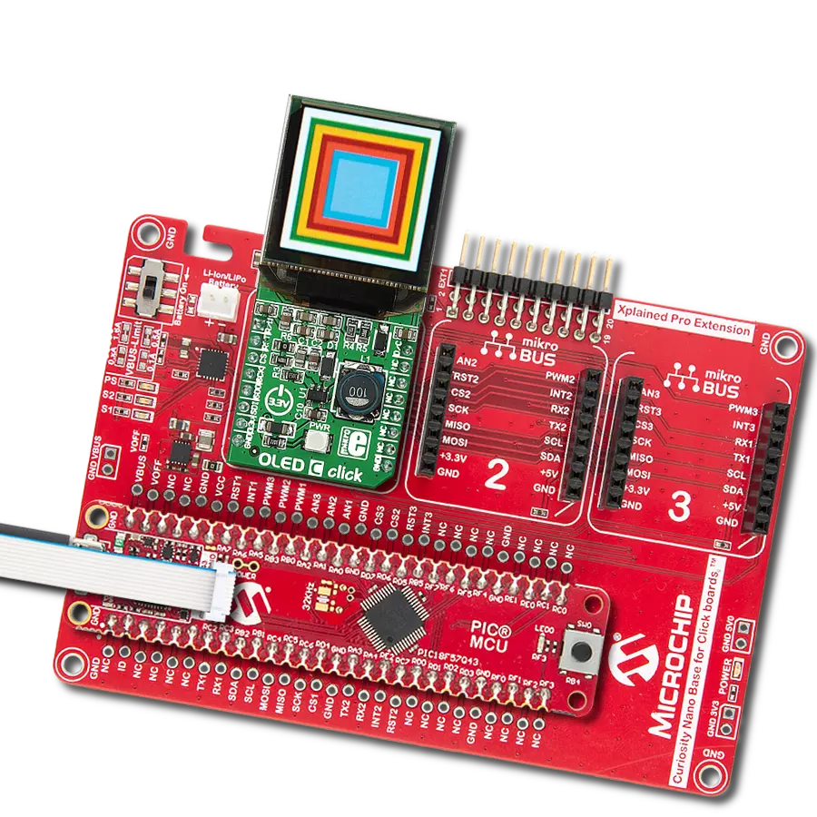
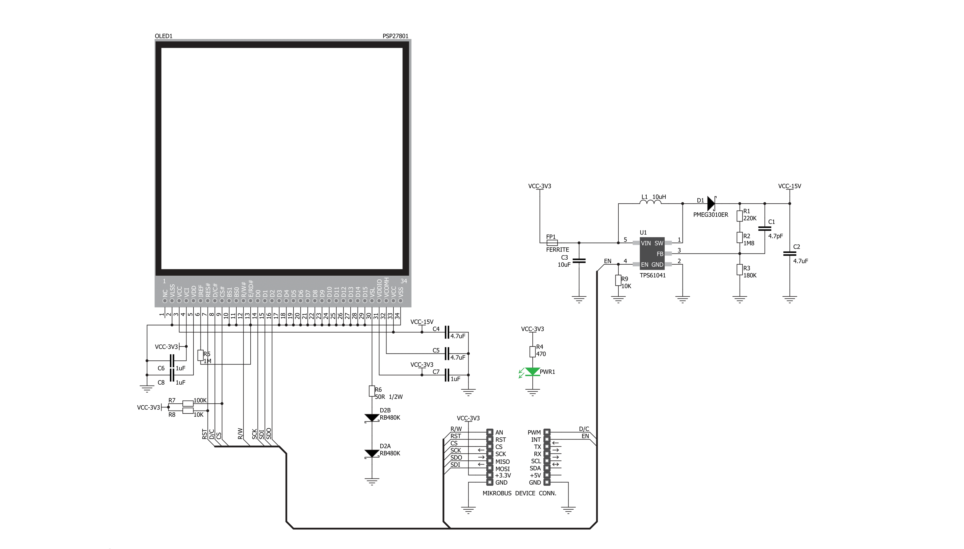
OLED C Click 基于深圳博兴世界科技的 PSP27801,这是一款 25x25mm、96x96px 的全彩方形 OLED 显示屏。此 OLED 显示屏使用的图形驱动器是 Solomon Systech 的 SSD1351 显示驱动 IC。图形驱动器内置了 128x128x18位 SRAM 显示缓冲区。它设计用于与共阴型 OLED 显示屏配合使用,并且具有并行(8080/6800)和串行接口用于通信。SSD1351 控制器还具有垂直和水平滚动、可编程帧率、行和列重映射、颜色交换等内置功能,并支持两种颜色模式:65K(6:5:6)和 262K(6:6:6)。
OLED C Click 使用标准的 4 线 SPI 串行接口或并行 接口与宿主 MCU 通信。它还占用了 mikroBUS™ 插座的其他几个引脚,例如用于重置 OLED 显示屏的 RST 引脚,以及仅用于并行通信的 mikroBUS™ 插座的 R/W 引脚,在使用串行通信时应将其拉低至逻辑低状态。D/C 是数据/命令引脚,与 CS 引脚紧密连接,因为当 CS 处于低逻辑电平时,显示器期望接收数据或命令。除了从 3.3V mikroBUS™ 电源轨获取的显示器的主电源外,PSP27801 还有另一个电源引脚,更 准确地说是其 DC/DC 转换器电路的电源供应。因
此,这款 Click board™ 使用了一个低功耗的板载升压转换器 TPS61041,可以通过 mikroBUS™ 插座的 EN 引脚开启或关闭,提供从 3.3V mikroBUS™ 轨输出的 15V 电源。EN 引脚开启或关闭升压转换器,从而 - 开启或关闭 OLED 屏幕本身。此 Click board™ 只能在 3.3V 逻辑电压水平下运行。使用不同逻辑电平的 MCU 之前,必须进行适当的逻辑电压水平转换。此外,它还配备了一个包含功能和示例代码的库,可用作进一步开发的参考。

功能概述
开发板
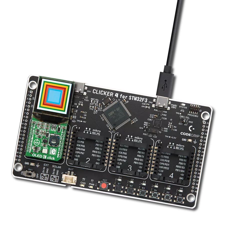
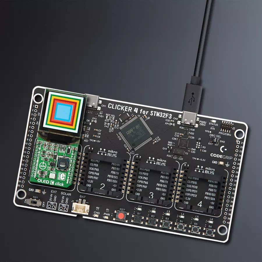
Clicker 4 for STM32F3 是一款紧凑型开发板,作为完整的解决方案而设计,可帮助用户快速构建具备独特功能的定制设备。该板搭载 STMicroelectronics 的 STM32F302VCT6 微控制器,配备四个 mikroBUS™ 插槽用于连接 Click boards™、完善的电源管理功能以及其他实用资源,是快速开发各类应用的理想平台。其核心 MCU STM32F302VCT6 基于高性能
Arm® Cortex®-M4 32 位处理器,运行频率高达 168MHz,处理能力强大,能够满足各种高复杂度任务的需求,使 Clicker 4 能灵活适应多种应用场景。除了两个 1x20 引脚排针外,板载最显著的连接特性是四个增强型 mikroBUS™ 插槽,支持接入数量庞大的 Click boards™ 生态系统,该生态每日持续扩展。Clicker 4 各功能区域标识清晰,界面直观简洁,极大
提升使用便捷性和开发效率。Clicker 4 的价值不仅在于加速原型开发与应用构建阶段,更在于其作为独立完整方案可直接集成至实际项目中,无需额外硬件修改。四角各设有直径 4.2mm(0.165")的安装孔,便于通过螺丝轻松固定。对于多数应用,只需配套一个外壳,即可将 Clicker 4 开发板转化为完整、实用且外观精美的定制系统。

微控制器概述
MCU卡片 / MCU

建筑
ARM Cortex-M4
MCU 内存 (KB)
256
硅供应商
STMicroelectronics
引脚数
100
RAM (字节)
40960
使用的MCU引脚
mikroBUS™映射器
“仔细看看!”
Click board™ 原理图
一步一步来
项目组装

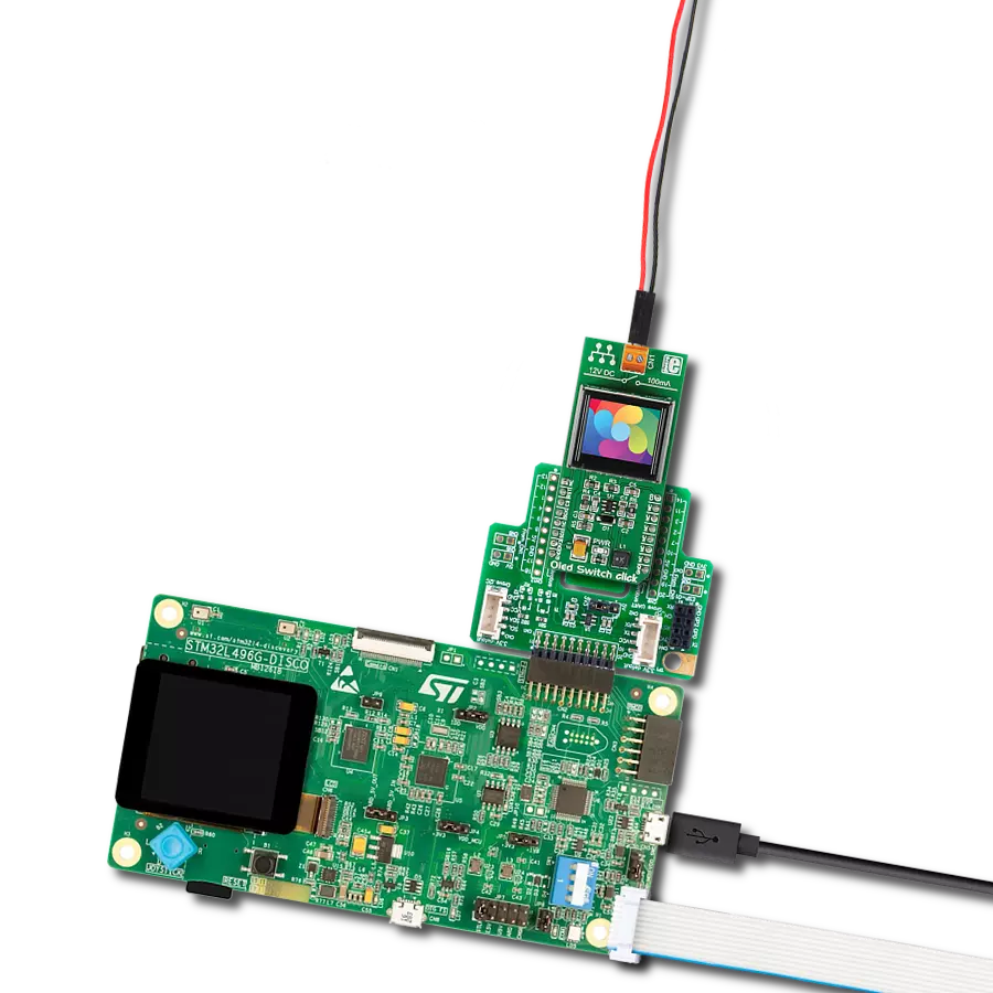
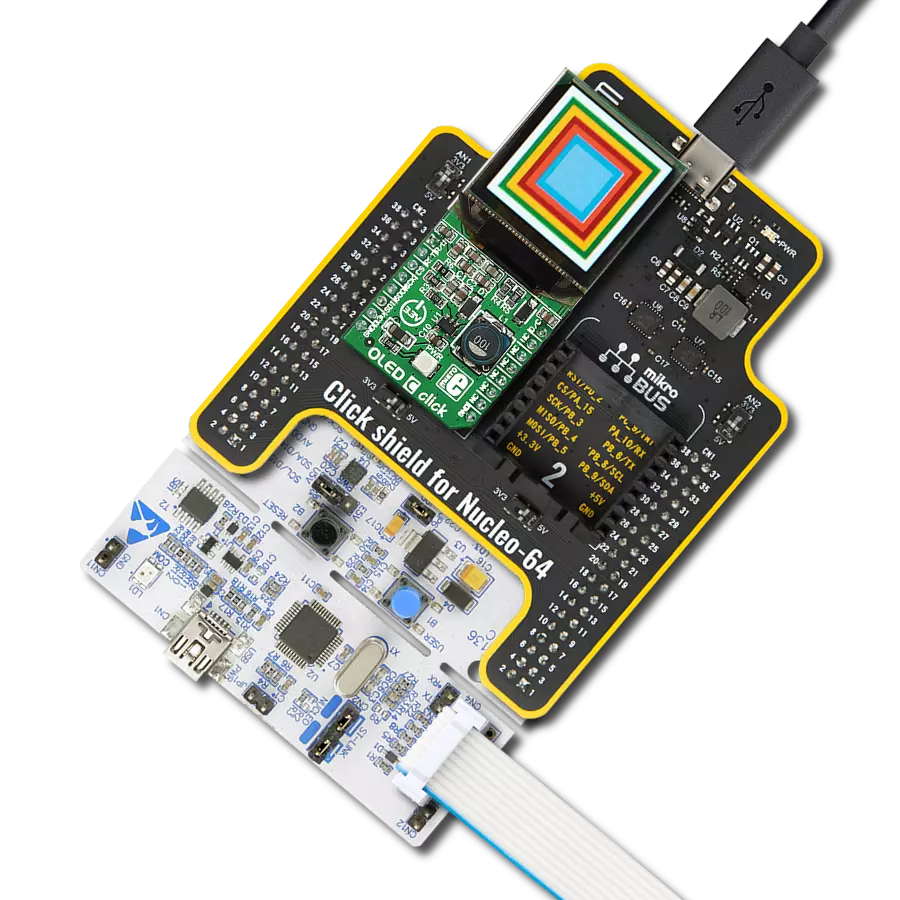
从选择您的开发板和Click板™开始。以CLICKER 4 for STM32F302VCT6作为您的开发板开始。


实时跟踪您的结果
应用程序输出
1. 应用程序输出 - 在调试模式下,“应用程序输出”窗口支持实时数据监控,直接提供执行结果的可视化。请按照提供的教程正确配置环境,以确保数据正确显示。

2. UART 终端 - 使用UART Terminal通过USB to UART converter监视数据传输,实现Click board™与开发系统之间的直接通信。请根据项目需求配置波特率和其他串行设置,以确保正常运行。有关分步设置说明,请参考提供的教程。

3. Plot 输出 - Plot功能提供了一种强大的方式来可视化实时传感器数据,使趋势分析、调试和多个数据点的对比变得更加直观。要正确设置,请按照提供的教程,其中包含使用Plot功能显示Click board™读数的分步示例。在代码中使用Plot功能时,请使用以下函数:plot(insert_graph_name, variable_name);。这是一个通用格式,用户需要将“insert_graph_name”替换为实际图表名称,并将“variable_name”替换为要显示的参数。

软件支持
库描述
此库包含 OLED C Click 驱动程序的 API。
关键功能:
oledc_fill_screen- 填充屏幕。oledc_image- 绘制 BMP 图像。
开源
代码示例
完整的应用程序代码和一个现成的项目可以通过NECTO Studio包管理器直接安装到NECTO Studio。 应用程序代码也可以在MIKROE的GitHub账户中找到。
/*!
 * \file
 * \brief OledC Click example
 *
 * # Description
 * This demo demonstrates the use of the OLED C Click board and the control of
 * the OLED C display.
 *
 * The demo application is composed of two sections :
 *
 * ## Application Init
 * Initializes driver init and OLED C init and sets full screen on white color
 * with writting demo text.
 *
 * ## Application Task
 * This function is composed of three sections :
 *  -  Display demo rectangle.
 *  -  Display demo line.
 *  -  Display demo image.
 *
 * \author MikroE Team
 *
 */
// ------------------------------------------------------------------- INCLUDES

#include "board.h"
#include "log.h"
#include "oledc.h"
#include "oledc_image.h"
#ifndef IMAGE_MODE_ONLY
#include "oledc_font.h"
#endif

// ------------------------------------------------------------------ VARIABLES

static oledc_t oledc;
static log_t logger;

#define text1 "Hello"
#define text2  "this is the demo"
#define text3  "for OLED C Click"

// ------------------------------------------------------ APPLICATION FUNCTIONS

void application_init ( void )
{
    log_cfg_t log_cfg;
    oledc_cfg_t cfg;

    /**
     * Logger initialization.
     * Default baud rate: 115200
     * Default log level: LOG_LEVEL_DEBUG
     * @note If USB_UART_RX and USB_UART_TX
     * are defined as HAL_PIN_NC, you will
     * need to define them manually for log to work.
     * See @b LOG_MAP_USB_UART macro definition for detailed explanation.
     */
    LOG_MAP_USB_UART( log_cfg );
    log_init( &logger, &log_cfg );
    log_info( &logger, "---- Application Init ----" );

    //  Click initialization.

    oledc_cfg_setup( &cfg );
    OLEDC_MAP_MIKROBUS( cfg, MIKROBUS_1 );
    oledc_init( &oledc, &cfg );

    oledc_default_cfg( &oledc );
    oledc_fill_screen( &oledc, 0xFFFF );

#ifndef IMAGE_MODE_ONLY
    oledc_set_font( &oledc, guiFont_Tahoma_8_Regular, 0 );
    oledc_text( &oledc, text1, 15, 10 );
    oledc_text( &oledc, text2, 5, 30 );
    oledc_text( &oledc, text3, 5, 45 );
#endif
    Delay_ms ( 1000 );
}

void application_task ( void )
{
    oledc_fill_screen( &oledc, 0xFFFF );
    Delay_100ms();

    // Rectangle demo
    oledc_rectangle( &oledc, 0, 0, 96, 96, 0xF000 );
    Delay_ms ( 500 );
    oledc_rectangle( &oledc, 5, 5, 91, 91, 0xFF00 );
    Delay_ms ( 500 );
    oledc_rectangle( &oledc, 10, 10, 86, 86, 0x00F0 );
    Delay_ms ( 500 );
    oledc_rectangle( &oledc, 15, 15, 81, 81, 0x0F0F );
    Delay_ms ( 500 );
    oledc_rectangle( &oledc, 20, 20, 76, 76, 0xF000 );
    Delay_ms ( 500 );
    oledc_rectangle( &oledc, 25, 25, 71, 71, 0xFF00 );
    Delay_100ms();

    // Line demo
    oledc_rectangle( &oledc, 25, 25, 71, 27, 0 );
    Delay_100ms();
    oledc_rectangle( &oledc, 25, 71, 71, 73, 0 );
    Delay_100ms();
    oledc_rectangle( &oledc, 25, 25, 27, 71, 0 );
    Delay_100ms();
    oledc_rectangle( &oledc, 68, 25, 71, 71, 0 );
    Delay_ms ( 1000 );
    Delay_ms ( 1000 );
    Delay_ms ( 1000 );


    // Image demo
    oledc_image( &oledc, mikroe_with_slogan96x96, 0, 0 );
    Delay_ms ( 1000 );
    Delay_ms ( 1000 );
}

int main ( void )
{
    /* Do not remove this line or clock might not be set correctly. */
    #ifdef PREINIT_SUPPORTED
    preinit();
    #endif

    application_init( );

    for ( ; ; )
    {
        application_task( );
    }

    return 0;
}


// ------------------------------------------------------------------------ END
额外支持
资源
类别:OLED