使用ST25DV16K和STM32F302VC创造更智能、更互动的数字体验
触摸并变革:NFC读卡器重塑您的数字格局
已发布 7月 22, 2025
点击板
NFC Tag 4 Click
开发板
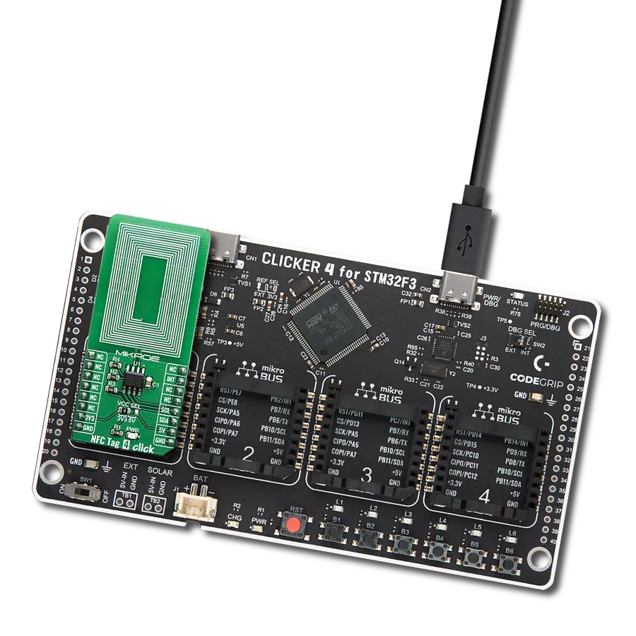
CLICKER 4 for STM32F302VCT6
编译器
NECTO Studio
微控制器单元
STM32F302VC
拥抱NFC体验,看看它是如何从简单的数据共享扩展到设备控制,为您与数字世界的互动提供更加连接和高效的方式。
A
A
硬件概览
它是如何工作的?
NFC Tag 4 Click基于STMicroelectronics的ST25DV16,这是一款紧凑的NFC标签IC。由于大部分接口和EEPROM存储器电路已经集成在ST25DV16K IC上,因此Click板™本身的组件数量相对较少。串行接口线(I2C / SMBus兼容)、以及GPO引脚(也可以使用开漏配置)由板载电阻上拉。2线接口被路由到mikroBUS™的相应I2C线(SCK和SDA),而主IC的GPO引脚被路由到mikroBUS™的INT引脚。ST25DV16K使用I2C/SMBus兼容的通信接口,提供快速传输模式(FTM),通过256字节缓冲区Mailbox在RF和接触世界之间实现快速链接。这个动态的256字节邮箱缓冲区可以通过RF或I2C填
充或清空。还有INT引脚可用,指示来自接触侧的传入事件,如RF场变化、正在进行的RF活动、RF写入完成或Mailbox消息可用性。内置的能量收集元件可以在外部条件允许时提供微瓦级的电力。集成的RF管理允许NFC Tag 4 click忽略RF请求。所有这些功能都可以通过设置ST25DV16K的静态和/或动态寄存器来进行编程。ST25DVxxx可以使用位于E2系统区域的配置寄存器进行部分定制。有关所有寄存器的更多信息可以在ST25DV16K的数据手册中找到。但是,提供的库包含了简化NFC Tag 4 click使用的功能。附带的应用示例演示了它们的功能,可用作定制设计的参考。为了确保不需要外部组件即可使用它,这个Click
Board™包含了PCB上的集成天线。天线线圈经过正确调谐,可以用于使用ISO/IEC 15693和ISO 18000-3模式1协议对设备进行供电和访问。电力通过NFC Tag 4 click和正在使用的NFC Reader的耦合天线以13.56 MHz的无线电频率传输给ST25DV16K。ISO 15693标准将操作场的载波频率(fC)定义为13.56 MHz ±7 kHz。这个Click板™可以使用VCC SEL跳线选择3.3V或5V逻辑电压电平操作。这样,既可以使3.3V也可以使5V的MCU正确使用通信线路。此外,这个Click板™配备了一个包含易于使用的功能和示例代码的库,可用作进一步开发的参考。


功能概述
开发板
Clicker 4 for STM32F3 是一款紧凑型开发板,作为完整的解决方案而设计,可帮助用户快速构建具备独特功能的定制设备。该板搭载 STMicroelectronics 的 STM32F302VCT6 微控制器,配备四个 mikroBUS™ 插槽用于连接 Click boards™、完善的电源管理功能以及其他实用资源,是快速开发各类应用的理想平台。其核心 MCU STM32F302VCT6 基于高性能
Arm® Cortex®-M4 32 位处理器,运行频率高达 168MHz,处理能力强大,能够满足各种高复杂度任务的需求,使 Clicker 4 能灵活适应多种应用场景。除了两个 1x20 引脚排针外,板载最显著的连接特性是四个增强型 mikroBUS™ 插槽,支持接入数量庞大的 Click boards™ 生态系统,该生态每日持续扩展。Clicker 4 各功能区域标识清晰,界面直观简洁,极大
提升使用便捷性和开发效率。Clicker 4 的价值不仅在于加速原型开发与应用构建阶段,更在于其作为独立完整方案可直接集成至实际项目中,无需额外硬件修改。四角各设有直径 4.2mm(0.165")的安装孔,便于通过螺丝轻松固定。对于多数应用,只需配套一个外壳,即可将 Clicker 4 开发板转化为完整、实用且外观精美的定制系统。

微控制器概述
MCU卡片 / MCU

建筑
ARM Cortex-M4
MCU 内存 (KB)
256
硅供应商
STMicroelectronics
引脚数
100
RAM (字节)
40960
使用的MCU引脚
mikroBUS™映射器
“仔细看看!”
Click board™ 原理图

一步一步来
项目组装

从选择您的开发板和Click板™开始。以CLICKER 4 for STM32F302VCT6作为您的开发板开始。


实时跟踪您的结果
应用程序输出
1. 应用程序输出 - 在调试模式下,“应用程序输出”窗口支持实时数据监控,直接提供执行结果的可视化。请按照提供的教程正确配置环境,以确保数据正确显示。

2. UART 终端 - 使用UART Terminal通过USB to UART converter监视数据传输,实现Click board™与开发系统之间的直接通信。请根据项目需求配置波特率和其他串行设置,以确保正常运行。有关分步设置说明,请参考提供的教程。

3. Plot 输出 - Plot功能提供了一种强大的方式来可视化实时传感器数据,使趋势分析、调试和多个数据点的对比变得更加直观。要正确设置,请按照提供的教程,其中包含使用Plot功能显示Click board™读数的分步示例。在代码中使用Plot功能时,请使用以下函数:plot(insert_graph_name, variable_name);。这是一个通用格式,用户需要将“insert_graph_name”替换为实际图表名称,并将“variable_name”替换为要显示的参数。

软件支持
库描述
该库包含 NFC Tag 4 Click 驱动程序的 API。
关键功能:
nfctag4_password_present- 此功能向设备提供密码,以打开I2C安全会话nfctag4_enable_mailbox- 此功能启用或禁用邮箱功能nfctag4_enable_rf- 此功能启用或禁用RF功能
开源
代码示例
完整的应用程序代码和一个现成的项目可以通过NECTO Studio包管理器直接安装到NECTO Studio。 应用程序代码也可以在MIKROE的GitHub账户中找到。
/*!
 * \file
 * \brief NfcTag4 Click example
 *
* # Description
 * This example showcases how to configure and use the NFC Tag 4 Click. The Click is an NFC tag
 * interface which uses the I2C serial interface and an RF link interface in order to communicate.
 * The example requires the ST25 NFC Tap application which can be downloaded to your phone.
 *
 * The demo application is composed of two sections :
 *
 * ## Application Init
 * This function initializes and configures the logger and Click modules.
 *
 * ## Application Task
 * This function waits for the interrupt signal, after which it expects data transfers. Once
 * some data has been detected it will open a communication channel with the device transmitting
 * it and show the received data in the UART console.
 *
 * \author MikroE Team
 *
 */
// ------------------------------------------------------------------- INCLUDES

#include "board.h"
#include "log.h"
#include "nfctag4.h"

// ------------------------------------------------------------------ VARIABLES

static nfctag4_t nfctag4;
static log_t logger;

static uint8_t aux_buffer[ 258 ];
static uint16_t i;

static uint16_t message_length = 0;
static transfer_info info;

// ------------------------------------------------------- ADDITIONAL FUNCTIONS

void nfctag4_wait_for_int ()
{
    uint16_t timer_counter = 0;
    uint8_t int_pin_flag = 0;
    int_pin_flag = nfctag4_int_get( &nfctag4 );
    while ( ( int_pin_flag == 1 ) && ( timer_counter <= 300 ) )
    {
        Delay_ms ( 1 );
        timer_counter++;
        int_pin_flag = nfctag4_int_get( &nfctag4 );
    }

    if ( timer_counter <= 300 )
    {
        int_pin_flag = nfctag4_int_get( &nfctag4 );
        while ( int_pin_flag == 0 )
        {
            int_pin_flag = nfctag4_int_get( &nfctag4 );
        }
    }

    timer_counter = 0;
}

// ------------------------------------------------------ APPLICATION FUNCTIONS

void application_init ( void )
{
    log_cfg_t log_cfg;
    nfctag4_cfg_t cfg;

    /**
     * Logger initialization.
     * Default baud rate: 115200
     * Default log level: LOG_LEVEL_DEBUG
     * @note If USB_UART_RX and USB_UART_TX
     * are defined as HAL_PIN_NC, you will
     * need to define them manually for log to work.
     * See @b LOG_MAP_USB_UART macro definition for detailed explanation.
     */
    LOG_MAP_USB_UART( log_cfg );
    log_init( &logger, &log_cfg );
    log_info( &logger, "---- Application Init ----" );

    nfctag4_cfg_setup( &cfg );
    NFCTAG4_MAP_MIKROBUS( cfg, MIKROBUS_1 );
    nfctag4_init( &nfctag4, &cfg );

    nfctag4_default_cfg( &nfctag4 );
}

void application_task ( void )
{
    nfctag4_wait_for_int( );

    info.memory_area = NFCTAG4_MEMORY_DYNAMIC;
    info.register_address = NFCTAG4_DYNAMIC_REG_MB_CTRL;
    info.n_registers = 1;
    nfctag4_i2c_get( &nfctag4, &info, aux_buffer );

    if ( ( aux_buffer[ 0 ] & 0x04 ) == ( 0x04 ) )
    {
        nfctag4_wait_for_int( );
        info.memory_area = NFCTAG4_MEMORY_DYNAMIC;
        info.register_address = NFCTAG4_DYNAMIC_REG_MB_LEN;
        info.n_registers = 1;
        nfctag4_i2c_get( &nfctag4, &info, aux_buffer );
        message_length = aux_buffer[ 0 ];
        message_length++;
        nfctag4_wait_for_int( );
        info.memory_area = NFCTAG4_MEMORY_MAILBOX;
        info.register_address = NFCTAG4_MAILBOX_REG_BYTE_0;
        info.n_registers = message_length;
        nfctag4_i2c_get( &nfctag4, &info, aux_buffer );

        log_printf( &logger, "************* MESSAGE ***************\r\n" );
        log_printf( &logger, " ** Message length:  %u Bytes**\r\n", message_length );

        for ( i = 0; i < message_length; i++ )
        {
            log_printf( &logger, " %u : 0x%x\r\n", i, ( uint16_t ) aux_buffer[ i ] );
        }

        log_printf( &logger, "************** END ****************\r\n" );
    }
}

int main ( void )
{
    /* Do not remove this line or clock might not be set correctly. */
    #ifdef PREINIT_SUPPORTED
    preinit();
    #endif

    application_init( );

    for ( ; ; )
    {
        application_task( );
    }

    return 0;
}


// ------------------------------------------------------------------------ END
额外支持
资源
类别:RFID / NFC