使用TCM515和PIC32MZ1024EFH064为您的应用程序提供安全且节能的环境
随时随地自由沟通!
已发布 6月 26, 2024
点击板
EnOcean 3 Click
开发板
PIC32MZ clicker
编译器
NECTO Studio
微控制器单元
PIC32MZ1024EFH064
我们的超低功耗收发器网关模块旨在无缝集成EnOcean通信到您的物联网生态系统中,提升连接性和能源效率。
A
A
硬件概览
它是如何工作的?
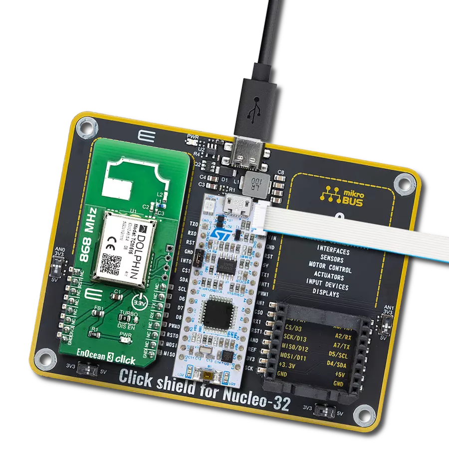
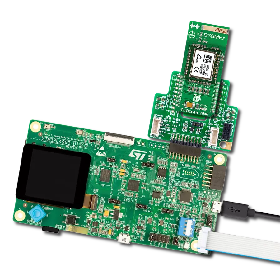
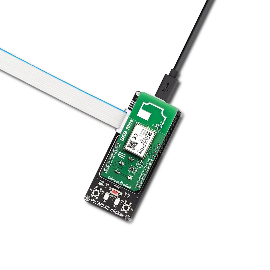
EnOcean 3 Click基于EnOcean的TCM515,这是一个在868MHz无线电频段工作的收发器网关模块。其完全集成的无线电功能使其能够通过板载PCB天线与其他设备进行通信,因此在测试此设备时不需要额外的天线。TCM 515可以工作在三种功能模式下:电报接收、电报发送、低功耗睡眠。在接收模式下,TCM 515处理接收到的无线电报,并验证正确的帧结构和校验和。在发送模式下,TCM 515通过其ESP3接口从外部主机接收要传输的无线电报。TCM515可以设置为低功耗睡眠模式,持续一段时间,在请求的睡眠周期到期后,TCM
515将自动唤醒并转换回接收模式。每个TMC515模块都包含其自己的EnOcean唯一无线电ID(EURID),可在传输过程中用于数据认证。除了这个功能,还可以根据正在设计的应用程序设置每个模块的基本ID或广播ID。另一个重要功能是SLF(安全级别格式),它指定用于与特定设备通信的加密、认证和滚动代码算法的参数,使得TCM515能够使用基于16字节安全密钥的AES128加密和解密电报。TCM 515通过标准化的EnOcean串行协议V3(ESP3)通信协议,在EnOcean无线电设备和通过UART接口连接的外部主机之间提供透
明的无线电链路。此模块的ESP3(UART)接口的默认接口速度为57600。此外,可以通过将TURBO跳线移动到EN位置,在上电时将默认的ESP3接口速度从57600比特每秒更改为460800比特每秒。这个Click Board™被设计为只能使用3.3V逻辑电压级操作。在将Click board™与逻辑电平为5V的MCU一起使用之前,应进行适当的逻辑电压级转换。一旦插入到开发系统的mikroBUS™插座中,它就可以立即使用。

功能概述
开发板
PIC32MZ Clicker 是一款紧凑型入门开发板,它将 Click 板™的灵活性带给您喜爱的微控制器,使其成为实现您想法的完美入门套件。它配备了一款板载 32 位带有浮点单元的 Microchip PIC32MZ 微控制器,一个 USB 连接器,LED 指示灯,按钮,一个 mikroProg 连接器,以及一个用于与外部电子设备接口的头部。得益于其紧凑的设计和清晰易识别的丝网标记,它提供了流畅且沉浸式的工作体验,允许在任
何情况下、任何地方都能访问。PIC32MZ Clicker 开 发套件的每个部分都包含了使同一板块运行最高效的必要组件。除了可以选择 PIC32MZ Clicker 的编程方式,使用 USB HID mikroBootloader 或通过外部 mikroProg 连接器为 PIC,dsPIC 或 PIC32 编程外,Clicker 板还包括一个干净且调节过的开发套件电源供应模块。USB Micro-B 连接可以提供多达 500mA 的电流,这足以操作所有板载和附加模块。所有
mikroBUS™ 本身支持的通信方法都在这块板上,包 括已经建立良好的 mikroBUS™ 插槽、重置按钮以及若干按钮和 LED 指示灯。PIC32MZ Clicker 是 Mikroe 生态系统的一个组成部分,允许您在几分钟内创建新的应用程序。它由 Mikroe 软件工具原生支持,得益于大量不同的 Click 板™(超过一千块板),其数量每天都在增长,它涵盖了原型制作的许多方面。

微控制器概述
MCU卡片 / MCU

建筑
PIC32
MCU 内存 (KB)
1024
硅供应商
Microchip
引脚数
64
RAM (字节)
524288
使用的MCU引脚
mikroBUS™映射器
“仔细看看!”
Click board™ 原理图

一步一步来
项目组装

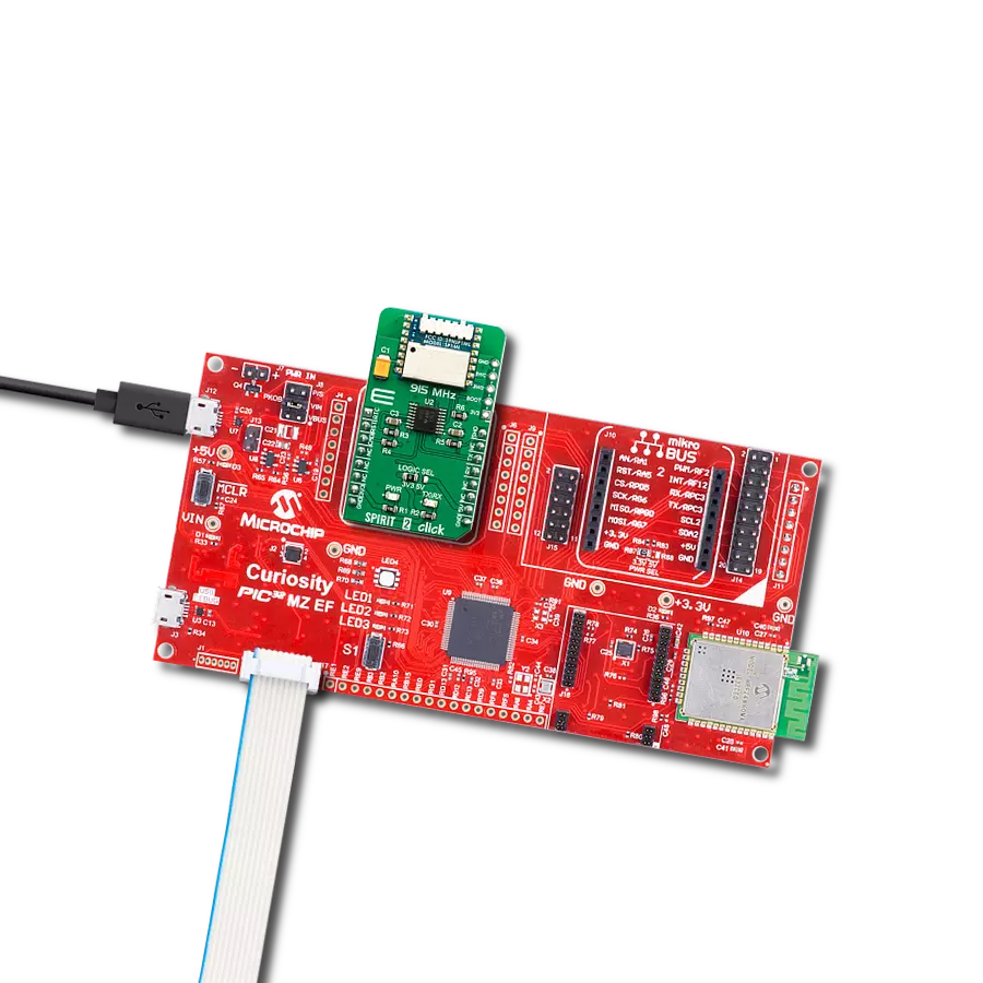
从选择您的开发板和Click板™开始。以PIC32MZ clicker作为您的开发板开始。


软件支持
库描述
该库包含 EnOcean 3 Click 驱动程序的 API。
关键功能:
enocean3_uart_isr- UART中断例程函数。enocean3_response_handler_set- 处理程序设置函数。enocean3_send_packet- 数据包发送函数。
开源
代码示例
完整的应用程序代码和一个现成的项目可以通过NECTO Studio包管理器直接安装到NECTO Studio。 应用程序代码也可以在MIKROE的GitHub账户中找到。
/*!
 * \file
 * \brief Enocean3 Click example
 *
 * # Description
 * This example reads and processes data from EnOcean 3 Clicks.
 *
 * The demo application is composed of two sections :
 *
 * ## Application Init
 * Initializes the driver and sets the driver handler.
 *
 * ## Application Task
 * Reads the received data and parses it on the USB UART if the response buffer is ready.
 *
 * ## Additional Function
 * - enocean3_process - The general process of collecting data the module sends.
 * - make_response - Driver handler function which stores data in the response buffer.
 * - log_response - Logs the module response on the USB UART.
 * - log_example - Logs button events on the USB UART.
 * - check_response - Checks if the response is ready and logs button events.
 *
 * \author MikroE Team
 *
 */
// ------------------------------------------------------------------- INCLUDES

#include "board.h"
#include "log.h"
#include "enocean3.h"
#include "string.h"

// ------------------------------------------------------------------ VARIABLES

static enocean3_t enocean3;
static log_t logger;

enocean3_packet_t response;
uint16_t response_size_cnt;
uint8_t rsp_check;

// ------------------------------------------------------- ADDITIONAL FUNCTIONS

void make_response( enocean3_packet_t *rsp, uint16_t *rsp_length_size )
{
    uint16_t rsp_cnt;

    for ( rsp_cnt = 0; rsp_cnt < rsp->data_length; rsp_cnt++ )
    {
        response.data_buff[ rsp_cnt ] = rsp->data_buff[ rsp_cnt ];
    }

    response.data_length = rsp->data_length;
    response.opt_length  = rsp->opt_length;
    response.packet_type = rsp->packet_type;
    response_size_cnt    = *rsp_length_size;
}

void log_response( )
{
    uint16_t rsp_cnt;

    if ( rsp_check == 1 )
    {
        log_printf( &logger, "OPCODE + PARAM : ", rsp_check );
        rsp_check = 0;
    }

    for ( rsp_cnt = 0; rsp_cnt < response.data_length; rsp_cnt++ )
    {
        log_printf( &logger, "0x%.2X ", ( uint16_t ) response.data_buff[ rsp_cnt ] );
    }

    if ( response_size_cnt == 1 )
    {
        log_printf( &logger, "\r\n" );
        rsp_check = 1;
    }
}

void log_example( )
{
    switch ( response.data_buff[ 1 ] )
    {
        case 0x00:
        {
            log_printf( &logger, "* Button is released *\r\n" );
            break;
        }
        case 0x10 :
        {
            log_printf( &logger, "* Button 1 is pressed *\r\n" );
            break;
        }
        case 0x30 :
        {
            log_printf( &logger, "* Button 3 is pressed *\r\n" );
            break;
        }
        case 0x50 :
        {
            log_printf( &logger, "* Button 5 is pressed *\r\n" );
            break;
        }
        case 0x70 :
        {
            log_printf( &logger, "* Button 7 is pressed *\r\n" );
            break;
        }
        case 0x15 :
        {
            log_printf( &logger, "* Buttons 1 and 5 are pressed *\r\n" );
            break;
        }
        case 0x17 :
        {
            log_printf( &logger, "* Buttons 1 and 7 are pressed *\r\n" );
            break;
        }
        case 0x35 :
        {
            log_printf( &logger, "* Buttons 3 and 5 are pressed *\r\n" );
            break;
        }
        case 0x37 :
        {
            log_printf( &logger, "* Buttons 3 and 7 are pressed *\r\n" );
            break;
        }
        default :
        {
            break;
        }
    }
}

void check_response( )
{
    uint8_t response_ready;

    response_ready = enocean3_response_ready( &enocean3 );

    if ( response_ready == ENOCEAN3_RESPONSE_READY )
    {
        log_example( );
    }
}

// ------------------------------------------------------ APPLICATION FUNCTIONS

void application_init ( void )
{
    log_cfg_t log_cfg;
    enocean3_cfg_t cfg;

    /**
     * Logger initialization.
     * Default baud rate: 115200
     * Default log level: LOG_LEVEL_DEBUG
     * @note If USB_UART_RX and USB_UART_TX
     * are defined as HAL_PIN_NC, you will
     * need to define them manually for log to work.
     * See @b LOG_MAP_USB_UART macro definition for detailed explanation.
     */
    LOG_MAP_USB_UART( log_cfg );
    log_init( &logger, &log_cfg );
    log_info( &logger, "---- Application Init ----" );

    //  Click initialization.

    enocean3_cfg_setup( &cfg );
    ENOCEAN3_MAP_MIKROBUS( cfg, MIKROBUS_1 );
    enocean3_init( &enocean3, &cfg );

    Delay_ms ( 500 );

    enocean3_response_handler_set( &enocean3, &make_response );
    rsp_check = 1;
}

void application_task ( void )
{
    enocean3_uart_isr ( &enocean3 );
    check_response ( );
    Delay_1ms( );
}

int main ( void )
{
    /* Do not remove this line or clock might not be set correctly. */
    #ifdef PREINIT_SUPPORTED
    preinit();
    #endif

    application_init( );

    for ( ; ; )
    {
        application_task( );
    }

    return 0;
}


// ------------------------------------------------------------------------ END