游戏时间从CTHS15CIC05RROW和MK64FN1M0VDC12开始
按下播放按钮,享受无尽的娱乐!

已发布 6月 24, 2024
点击板
Button PLAY Click
开发板
Clicker 2 for Kinetis
编译器
NECTO Studio
微控制器单元
MK64FN1M0VDC12
我们的PLAY按钮解决方案旨在提升用户参与度和享受度,提供一种无缝便捷的方式,使用户只需按一下按钮即可访问和体验他们喜爱的游戏、音乐和视频。
A
A
硬件概览
它是如何工作的?
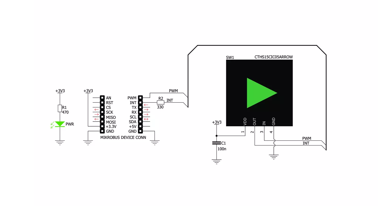
Button PLAY Click基于VCC(Visual Communications Company)的CTHS15CIC05ARROW,这是一款电容式触摸传感器显示器。该传感器提供了在顶部带有背光箭头图标的吸引人外壳中的电容触摸感应。此设备仅使用最少数量的引脚:仅有四个引脚暴露给用户。除了电源引脚(VCC和GND)之外,还使用了两个引脚。触摸检测通过CTHS15CIC05ARROW传感器的OUT引脚上的高电平逻辑指示,而IN引脚用于两个内部LED的电源,这两个LED连接在共阴
极配置中。LED的正向电压通常为3.2V。传感器的OUT引脚连接到mikroBUS™的INT引脚,而传感器的IN引脚连接到mikroBUS™的PWM引脚。即使在背光关闭时,触摸传感器顶部的箭头图标仍然可见,这要归功于传感器顶部的LEXAN™聚碳酸酯薄膜上的逆向打印图标。当内部LED点亮时,光线会穿过半透明的箭头图标,从而使箭头图标均匀发光。通过将PWM信号应用于IN引脚,可以在触摸时设计出有趣的照明效果。传感器IC、感应垫和两个集成LED封装在一个小方形外壳中,尺寸为
15mm x 15mm x 11mm,形成一个紧凑而坚固的触摸按钮。与机械按钮相比,它有许多优点:由于没有运动部件,它不会磨损,不会出现抖动或颤动效应,耐用且耐天气因素等。然而,它不能用于闭合电路,只能产生由主控MCU转换为适当动作的逻辑信号。即使在手湿的情况下或戴着某些手套时,该传感器也可以操作。触摸传感器还可以放置在高达3mm厚的透明玻璃或塑料层(如聚碳酸酯或丙烯酸)后面。虽然传感器在通电后会执行自校准,但如果位置固定,最好在这些情况下测试其功能。


功能概述
开发板
Clicker 2 for Kinetis 是一款紧凑型入门开发板,它将 Click 板™的灵活性带给您喜爱的微控制器,使其成为实现您想法的完美入门套件。它配备了一款板载 32 位 ARM Cortex-M4F 微控制器,NXP 半导体公司的 MK64FN1M0VDC12,两个 mikroBUS™ 插槽用于 Click 板™连接,一个 USB 连接器,LED 指示灯,按钮,一个 JTAG 程序员连接器以及两个 26 针头用于与外部电子设备的接口。其紧凑的设计和清晰、易识别的丝网标记让您能够迅速构建具有独特功能和特性
的小工具。Clicker 2 for Kinetis 开发套件的每个部分 都包含了使同一板块运行最高效的必要组件。除了可以选择 Clicker 2 for Kinetis 的编程方式,使用 USB HID mikroBootloader 或外部 mikroProg 连接器进行 Kinetis 编程外,Clicker 2 板还包括一个干净且调节过的开发套件电源供应模块。它提供了两种供电方式;通过 USB Micro-B 电缆,其中板载电压调节器为板上每个组件提供适当的电压水平,或使用锂聚合物 电池通过板载电池连接器供电。所有 mikroBUS™ 本
身支持的通信方法都在这块板上,包括已经建立良好的 mikroBUS™ 插槽、重置按钮和几个用户可配置的按钮及 LED 指示灯。Clicker 2 for Kinetis 是 Mikroe 生态系统的一个组成部分,允许您在几分钟内创建新的应用程序。它由 Mikroe 软件工具原生支持,得益于大量不同的 Click 板™(超过一千块板),其数量每天都在增长,它涵盖了原型制作的许多方面。

微控制器概述
MCU卡片 / MCU

建筑
ARM Cortex-M4
MCU 内存 (KB)
1024
硅供应商
NXP
引脚数
121
RAM (字节)
262144
使用的MCU引脚
mikroBUS™映射器
“仔细看看!”
Click board™ 原理图
一步一步来
项目组装

从选择您的开发板和Click板™开始。以Clicker 2 for Kinetis作为您的开发板开始。


实时跟踪您的结果
应用程序输出
1. 应用程序输出 - 在调试模式下,“应用程序输出”窗口支持实时数据监控,直接提供执行结果的可视化。请按照提供的教程正确配置环境,以确保数据正确显示。

2. UART 终端 - 使用UART Terminal通过USB to UART converter监视数据传输,实现Click board™与开发系统之间的直接通信。请根据项目需求配置波特率和其他串行设置,以确保正常运行。有关分步设置说明,请参考提供的教程。

3. Plot 输出 - Plot功能提供了一种强大的方式来可视化实时传感器数据,使趋势分析、调试和多个数据点的对比变得更加直观。要正确设置,请按照提供的教程,其中包含使用Plot功能显示Click board™读数的分步示例。在代码中使用Plot功能时,请使用以下函数:plot(insert_graph_name, variable_name);。这是一个通用格式,用户需要将“insert_graph_name”替换为实际图表名称,并将“variable_name”替换为要显示的参数。

软件支持
库描述
该库包含用于Button PLAY Click驱动程序的API。
关键功能:
buttonplay_pwm_stop- 此功能停止PWM模块输出buttonplay_get_button_state- 此功能读取INT引脚上的数字信号,以判断按钮是否被按下
开源
代码示例
完整的应用程序代码和一个现成的项目可以通过NECTO Studio包管理器直接安装到NECTO Studio。 应用程序代码也可以在MIKROE的GitHub账户中找到。
/*!
 * @file main.c
 * @brief Button Play Click Example.
 *
 * # Description
 * This example showcases how to initialize and use the whole family of Button clicks.
 * One library is used for every single one of them. They are simple touch detectors which
 * send a pressed/released signal and receive a PWM output which controls the backlight on the button.
 *
 * The demo application is composed of two sections :
 *
 * ## Application Init
 * This function initializes and configures the logger and click modules.
 *
 * ## Application Task
 * This example first increases the backlight on the button and then decreases the intensity of the backlight. When the button is touched,
 * reports the event in the console using UART communication.
 *
 * @author Nikola Peric
 *
 */

#include "board.h"
#include "log.h"
#include "buttonplay.h"

static buttonplay_t buttonplay;
static log_t logger;

void application_init ( void )
{
    log_cfg_t log_cfg;                 /**< Logger config object. */
    buttonplay_cfg_t buttonplay_cfg;   /**< Click config object. */

    /**
     * Logger initialization.
     * Default baud rate: 115200
     * Default log level: LOG_LEVEL_DEBUG
     * @note If USB_UART_RX and USB_UART_TX
     * are defined as HAL_PIN_NC, you will
     * need to define them manually for log to work.
     * See @b LOG_MAP_USB_UART macro definition for detailed explanation.
     */
    LOG_MAP_USB_UART( log_cfg );
    log_init( &logger, &log_cfg );
    log_info( &logger, " Application Init " );

    // Click initialization.

    buttonplay_cfg_setup( &buttonplay_cfg );
    BUTTONPLAY_MAP_MIKROBUS( buttonplay_cfg, MIKROBUS_1 );
    err_t init_flag  = buttonplay_init( &buttonplay, &buttonplay_cfg );
    if ( PWM_ERROR == init_flag )
    {
        log_error( &logger, " Application Init Error. " );
        log_info( &logger, " Please, run program again... " );

        for ( ; ; );
    }
    Delay_ms( 500 );

    buttonplay_set_duty_cycle ( &buttonplay, 0.0 );
    buttonplay_pwm_start( &buttonplay );

    log_info( &logger, " Application Task " );
}

void application_task ( void )
{
    static float duty_cycle;
    static uint8_t button_state;
    static uint8_t button_state_old;

    button_state = buttonplay_get_button_state( &buttonplay );

    if ( button_state && ( button_state != button_state_old ) )
    {
        log_printf( &logger, " <-- Button pressed --> \r\n" );
        for ( uint8_t n_cnt = 1; n_cnt <= 100; n_cnt++  )
        {
            duty_cycle = ( float ) n_cnt ;
            duty_cycle /= 100;
            buttonplay_set_duty_cycle( &buttonplay, duty_cycle );
            Delay_ms( 10 );
        }
        button_state_old = button_state;
    }
    else if ( !button_state && ( button_state != button_state_old ) )
    {
        for ( uint8_t n_cnt = 100; n_cnt > 0; n_cnt-- )
        {
            duty_cycle = ( float ) n_cnt ;
            duty_cycle /= 100;
            buttonplay_set_duty_cycle( &buttonplay,  duty_cycle );
            Delay_ms( 10 );
        }
        button_state_old = button_state;
    }
}

void main ( void )
{
    application_init( );

    for ( ; ; )
    {
        application_task( );
    }
}

// ------------------------------------------------------------------------ END


