使用 G6D-1A-ASI 和 MK64FN1M0VDC12 保持研究和实验的理想条件
您可信赖的全环境温度计

已发布 6月 25, 2024
点击板
Thermostat 2 Click
开发板
Clicker 2 for Kinetis
编译器
NECTO Studio
微控制器单元
MK64FN1M0VDC12
使用我们的温度测量技术,提前预防潜在的健康风险,该技术旨在为关键环境中的温度波动提供早期预警。
A
A
硬件概览
它是如何工作的?
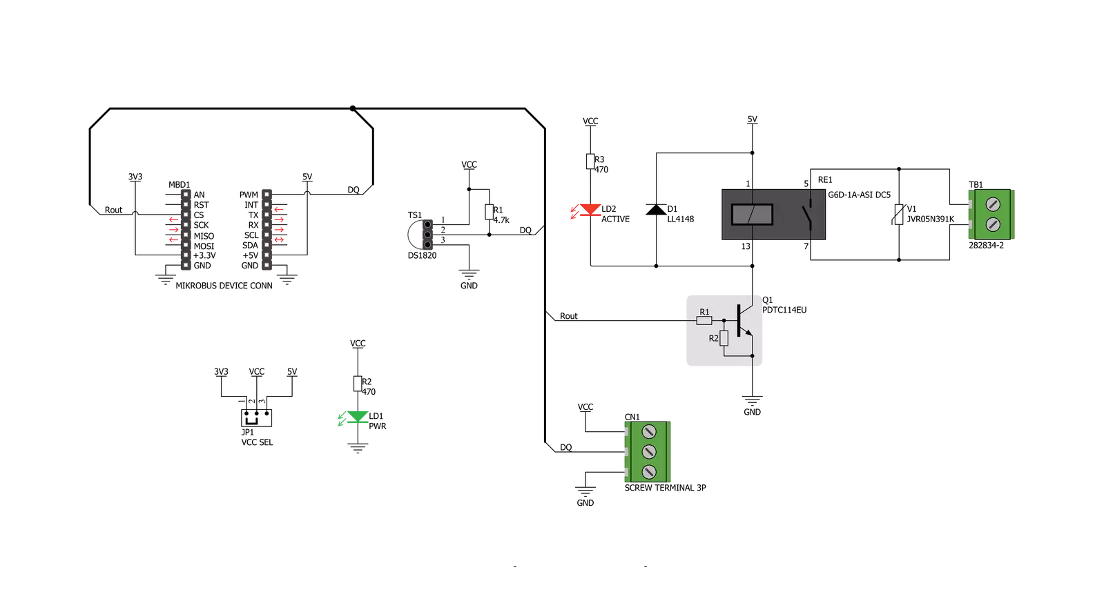
Thermostat 2 Click设计时没有主要IC;它允许使用外部连接的热传感器。它可以与使用1-Wire®通信的DS1820兼容传感器接口。Click board™配备了一个3针母插座,可以用于安装TO-92封装的DS1820兼容传感器。还配有一个3极螺钉端子,如果传感器需要安装在远程位置(例如加热组件上),则可以使用该端子。螺钉端子与插座共享其线路。通过mikroBUS™的PWM引脚与主机MCU进行1-Wire®通信。根据通过1-Wire®接口获得的温度信息,主机MCU可以采取必要的操作:它可以打开或关闭继电器的触点。Click board™使用了来自欧姆龙的G6D系列PCB电源继电器。这个高质量继电器可以在没有负载连接的情况下承受惊人的大量机械循环。然而,当其输出连接有显著负载时,微电弧会随着时间的推移导致触点磨损。最大负载电流为5A时,它可以承受高达70,000次
循环。其触点由银合金制成,具有出色的最大100mΩ的ON电阻。继电器通过低压侧内置线圈产生的磁场激活。线圈由主机MCU激活。线圈激活的电压为5V,线圈的电流为40mA。MCU无法直接驱动线圈,因此需要添加一个NPN晶体管。其基极由主机MCU控制,允许线圈从5V mikroBUS™电源轨吸取足够的电流。晶体管的基极被路由到Click board™的CS引脚。晶体管在同一外壳中打包了两个偏置电阻,因此可以直接在MCU引脚上使用,而无需外部偏置电阻。标记为ACTIVE的红色LED用于指示晶体管处于打开状态,并且电流正在通过继电器线圈。当线圈(或任何其他电感器)中的电流突然改变时,将产生反电动势,反对电流的变化。这有时会导致控制电路损坏:在这种情况下,晶体管将变为反向极化。为了防止这种情况的发生,在线圈两端添加了一个续流二
极管。在正常操作期间,该二极管不导通任何电流。然而,当线圈关闭时,反向极化将导致电流以最小阻力通过该二极管。这防止了反向(续流)电压的建立,从而保护了晶体管。输出上的触点可能连接到较高电压,并且可能会通过较大的电流。为防止这种情况下的高电压瞬变,续流二极管并不是可行的选择。因此,Thermostat 2 Click使用了压敏电阻(VDR)。当电压升高超过其额定钳位电压时,该组件会迅速降低其电阻。由于它将成为最小阻力的电流路径,因此过量的电压瞬变将通过VDR。在正常操作期间,当电压低于额定钳位电压时,VDR具有非常高的电阻,因此电流通过电路运行。Click board™的工作电压可以通过VCC SEL跳线选择。此跳线允许从mikroBUS™选择3.3V或5V。所选电压将应用于连接的DS1820传感器的VCC引脚。

功能概述
开发板
Clicker 2 for Kinetis 是一款紧凑型入门开发板,它将 Click 板™的灵活性带给您喜爱的微控制器,使其成为实现您想法的完美入门套件。它配备了一款板载 32 位 ARM Cortex-M4F 微控制器,NXP 半导体公司的 MK64FN1M0VDC12,两个 mikroBUS™ 插槽用于 Click 板™连接,一个 USB 连接器,LED 指示灯,按钮,一个 JTAG 程序员连接器以及两个 26 针头用于与外部电子设备的接口。其紧凑的设计和清晰、易识别的丝网标记让您能够迅速构建具有独特功能和特性
的小工具。Clicker 2 for Kinetis 开发套件的每个部分 都包含了使同一板块运行最高效的必要组件。除了可以选择 Clicker 2 for Kinetis 的编程方式,使用 USB HID mikroBootloader 或外部 mikroProg 连接器进行 Kinetis 编程外,Clicker 2 板还包括一个干净且调节过的开发套件电源供应模块。它提供了两种供电方式;通过 USB Micro-B 电缆,其中板载电压调节器为板上每个组件提供适当的电压水平,或使用锂聚合物 电池通过板载电池连接器供电。所有 mikroBUS™ 本
身支持的通信方法都在这块板上,包括已经建立良好的 mikroBUS™ 插槽、重置按钮和几个用户可配置的按钮及 LED 指示灯。Clicker 2 for Kinetis 是 Mikroe 生态系统的一个组成部分,允许您在几分钟内创建新的应用程序。它由 Mikroe 软件工具原生支持,得益于大量不同的 Click 板™(超过一千块板),其数量每天都在增长,它涵盖了原型制作的许多方面。

微控制器概述
MCU卡片 / MCU

建筑
ARM Cortex-M4
MCU 内存 (KB)
1024
硅供应商
NXP
引脚数
121
RAM (字节)
262144
使用的MCU引脚
mikroBUS™映射器
“仔细看看!”
Click board™ 原理图
一步一步来
项目组装

从选择您的开发板和Click板™开始。以Clicker 2 for Kinetis作为您的开发板开始。


实时跟踪您的结果
应用程序输出
1. 应用程序输出 - 在调试模式下,“应用程序输出”窗口支持实时数据监控,直接提供执行结果的可视化。请按照提供的教程正确配置环境,以确保数据正确显示。

2. UART 终端 - 使用UART Terminal通过USB to UART converter监视数据传输,实现Click board™与开发系统之间的直接通信。请根据项目需求配置波特率和其他串行设置,以确保正常运行。有关分步设置说明,请参考提供的教程。

3. Plot 输出 - Plot功能提供了一种强大的方式来可视化实时传感器数据,使趋势分析、调试和多个数据点的对比变得更加直观。要正确设置,请按照提供的教程,其中包含使用Plot功能显示Click board™读数的分步示例。在代码中使用Plot功能时,请使用以下函数:plot(insert_graph_name, variable_name);。这是一个通用格式,用户需要将“insert_graph_name”替换为实际图表名称,并将“variable_name”替换为要显示的参数。

软件支持
库描述
该库包含Thermostat 2 Click驱动程序的 API。
关键功能:
thermostat2_read_temperature- 该函数读取摄氏温度值。thermostat2_relay_state- 该函数打开/关闭继电器。
开源
代码示例
完整的应用程序代码和一个现成的项目可以通过NECTO Studio包管理器直接安装到NECTO Studio。 应用程序代码也可以在MIKROE的GitHub账户中找到。
/*!
 * @file main.c
 * @brief Thermostat 2 Click Example.
 *
 * # Description
 * This example demonstrates the use of Thermostat 2 click board by reading
 * and displaying the temperature in Celsius and turning the relay on/off
 * depending on the temperature value.
 * DS1820, DS18S20 and DS18B20 chips can be used in this example.
 *
 * The demo application is composed of two sections :
 *
 * ## Application Init
 * Initializes the driver and performs the click default configuration.
 *
 * ## Application Task
 * Reads and displays the temperature measured by the click board on the UART Terminal.
 * If the temperature goes beneath the THERMOSTAT2_TEMPERATURE_LIMIT,
 * the relay will be turned off while otherwise it will be turned on.
 * In both cases an appropriate message will be displayed on the terminal.
 *
 * @author Aleksandra Cvjetićanin
 *
 */

#include "board.h"
#include "log.h"
#include "thermostat2.h"

static thermostat2_t thermostat2;
static log_t logger;

void application_init ( void )
{
    log_cfg_t log_cfg;  /**< Logger config object. */
    thermostat2_cfg_t thermostat2_cfg;  /**< Click config object. */

    /**
     * Logger initialization.
     * Default baud rate: 115200
     * Default log level: LOG_LEVEL_DEBUG
     * @note If USB_UART_RX and USB_UART_TX
     * are defined as HAL_PIN_NC, you will
     * need to define them manually for log to work.
     * See @b LOG_MAP_USB_UART macro definition for detailed explanation.
     */
    LOG_MAP_USB_UART( log_cfg );
    log_init( &logger, &log_cfg );
    log_info( &logger, " Application Init " );

    // Click initialization.
    thermostat2_cfg_setup( &thermostat2_cfg );
    THERMOSTAT2_MAP_MIKROBUS( thermostat2_cfg, MIKROBUS_1 );
    if ( ONE_WIRE_ERROR == thermostat2_init( &thermostat2, &thermostat2_cfg ) )
    {
        log_error( &logger, " Communication init." );
        for ( ; ; );
    }

    if ( THERMOSTAT2_ERROR == thermostat2_default_cfg ( &thermostat2 ) )
    {
        log_error( &logger, " Default config." );
        for ( ; ; );
    }

    log_info( &logger, " Application Task " );
}

void application_task ( void )
{
    static uint8_t relay_state = 0xFF;
    float temperature;

    if ( THERMOSTAT2_OK == thermostat2_read_temperature ( &thermostat2, &temperature ) )
    {
        log_printf( &logger, " Temperature: %.2f C\r\n\n ", temperature );
    }

    if ( temperature < THERMOSTAT2_TEMPERATURE_LIMIT )
    {
        if ( relay_state != THERMOSTAT2_RELAY_ON )
        {
            log_info( &logger, " Relay is ON.\r\n " );
            thermostat2_relay_state ( &thermostat2, THERMOSTAT2_RELAY_ON );
            relay_state = THERMOSTAT2_RELAY_ON;
        }
    }
    else
    {
        if ( relay_state != THERMOSTAT2_RELAY_OFF )
        {
            log_info( &logger, " Relay is OFF.\r\n" );
            thermostat2_relay_state ( &thermostat2, THERMOSTAT2_RELAY_OFF );
            relay_state = THERMOSTAT2_RELAY_OFF;
        }
    }
}

int main ( void )
{
    /* Do not remove this line or clock might not be set correctly. */
    #ifdef PREINIT_SUPPORTED
    preinit();
    #endif

    application_init( );

    for ( ; ; )
    {
        application_task( );
    }

    return 0;
}

// ------------------------------------------------------------------------ END


