通过使用ISD3900和MK64FN1M0VDC12吸引观众并提升您的讲故事能力
您的个性化数字语音记录器
已发布 6月 28, 2024
点击板
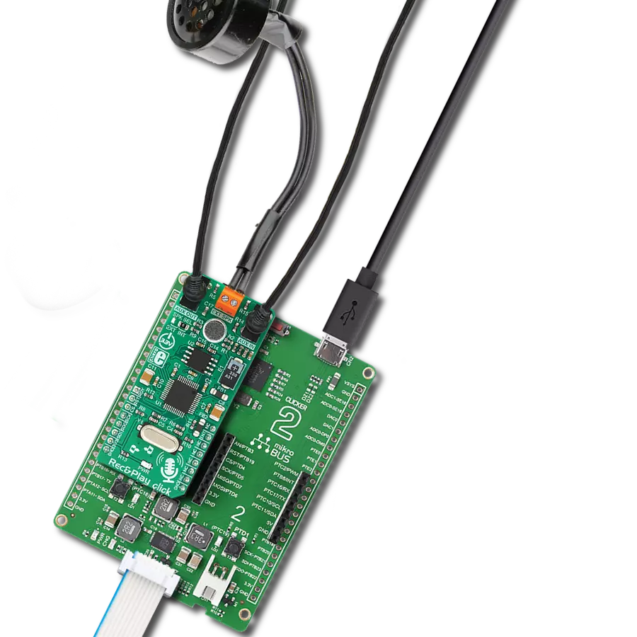
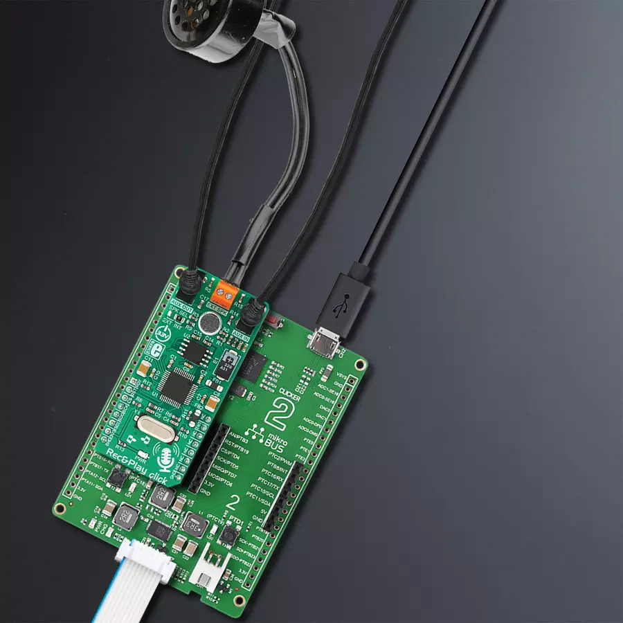
Rec&Play Click
开发板
Clicker 2 for Kinetis
编译器
NECTO Studio
微控制器单元
MK64FN1M0VDC12
了解我们的多消息录音和回放设备如何通过可定制的语音录音让您的回忆栩栩如生。
A
A
硬件概览
它是如何工作的?
Rec&Play Click基于Nuvoton的ISD3900,这是一款带有ChipCorder®技术的多消息录音和回放设备。由于其提供的众多有用功能,这款IC迅速获得了人气。除了多种压缩和解压缩CODEC外,它还具有完全可编程的信号路径,支持多种不同的信号类型,使得任何类型的基于消息的应用设计都非常简单。POS终端的声音通知、使用语音通知事件的家用电器,甚至是类似录音机的设备,都可以非常迅速地通过这个Click板™实现。ISD3900允许使用消息索引而不是内存位置:一旦存储,消息可以通过其索引调用。还可以构建宏脚本(语音宏)。为了实现开箱即用的功能,Click板™配备了一个小型全向驻极体麦克风和一个微型8Ω扬声器。麦克风可以捕捉声音或语音录音。录音可以通过应用自动增益控制(AGC)来增强,该功能动态改变输入增益,有助于获得最合适的信号电平。AGC功能以及许多其他功能可以通过SPI接口进行配置。微型钕磁扬声器(内部扬声器)的尺寸仅为15 x 11mm,设计为输出高达0.7W的连续功率。它由ISD3900
IC驱动,集成了一个小型0.5W D类放大器。内部扬声器的边缘有粘合剂,可以轻松安装在小的谐振箱内,从而增强其输出。然而,该扬声器仅在室内使用时效果较好。标记为EXT SPK的2极端子允许连接外部无源扬声器箱。当SPK SEL移动到EXT位置时,内部D类放大器的输出将路由到该连接器,而不是内部扬声器。一个差分BTL(桥接负载)输出也通过EXT SPK连接器提供,允许使用带有差分输入的外部放大器。AUX IN和AUX OUT是3.5mm插孔连接器,用于连接线路级输入和输出信号。AUX OUT连接器提供单端线路级输出,与大多数商业放大器、主动桌面扬声器、音响监视器等兼容。AUX IN是单端线路级输入,允许从家用PC、电视机、MP3播放器和任何其他设备捕捉声音,这些设备配备了线路输出连接器。音频采样率由外部晶体振荡器派生,额定为4.096MHz。该晶体振荡器允许主采样率高达32kHz。也可以使用较低的采样率,从而降低音质。除了采样率,音质还受所用压缩算法的影响。ISD3900支持多种不同的
CODEC。有关更多信息,请参阅ISD3900 IC数据手册。除了ISD3900,此Click板™还包含另一个IC:它是标记为W25Q64的非易失性存储模块,这是Winbond的64 Mbit串行闪存。该存储模块具有64 Mbit密度,以8位字排列,允许存储长达32分钟的音频。ISD3900具有一组控制设备各个方面的寄存器:通过SPI接口写入适当的配置寄存器可以配置整个声音路径。ISD3900还处理与Flash相关的命令,如格式化、擦除、读取、写入等。尽管简化了,编程ISD3900可能看起来很复杂,但在MIKROE环境中使用时,操作Click板™非常容易。它由兼容mikroSDK的库支持,包含加速软件开发的功能。提供了几种预配置的声音路径设置,节省了宝贵的时间。此Click板™只能在3.3V逻辑电压水平下运行。如果使用不同逻辑电平的MCU,必须进行适当的逻辑电压电平转换。此外,它配备了包含函数和示例代码的库,可作为进一步开发的参考。

功能概述
开发板
Clicker 2 for Kinetis 是一款紧凑型入门开发板,它将 Click 板™的灵活性带给您喜爱的微控制器,使其成为实现您想法的完美入门套件。它配备了一款板载 32 位 ARM Cortex-M4F 微控制器,NXP 半导体公司的 MK64FN1M0VDC12,两个 mikroBUS™ 插槽用于 Click 板™连接,一个 USB 连接器,LED 指示灯,按钮,一个 JTAG 程序员连接器以及两个 26 针头用于与外部电子设备的接口。其紧凑的设计和清晰、易识别的丝网标记让您能够迅速构建具有独特功能和特性
的小工具。Clicker 2 for Kinetis 开发套件的每个部分 都包含了使同一板块运行最高效的必要组件。除了可以选择 Clicker 2 for Kinetis 的编程方式,使用 USB HID mikroBootloader 或外部 mikroProg 连接器进行 Kinetis 编程外,Clicker 2 板还包括一个干净且调节过的开发套件电源供应模块。它提供了两种供电方式;通过 USB Micro-B 电缆,其中板载电压调节器为板上每个组件提供适当的电压水平,或使用锂聚合物 电池通过板载电池连接器供电。所有 mikroBUS™ 本
身支持的通信方法都在这块板上,包括已经建立良好的 mikroBUS™ 插槽、重置按钮和几个用户可配置的按钮及 LED 指示灯。Clicker 2 for Kinetis 是 Mikroe 生态系统的一个组成部分,允许您在几分钟内创建新的应用程序。它由 Mikroe 软件工具原生支持,得益于大量不同的 Click 板™(超过一千块板),其数量每天都在增长,它涵盖了原型制作的许多方面。

微控制器概述
MCU卡片 / MCU

建筑
ARM Cortex-M4
MCU 内存 (KB)
1024
硅供应商
NXP
引脚数
121
RAM (字节)
262144
使用的MCU引脚
mikroBUS™映射器
“仔细看看!”
Click board™ 原理图

一步一步来
项目组装

从选择您的开发板和Click板™开始。以Clicker 2 for Kinetis作为您的开发板开始。


软件支持
库描述
该库包含Rec&Play Click驱动程序的 API。
关键功能:
recplay_read_status- 查询ISD3900设备状态的功能recplay_erase_msg- 擦除从指定地址开始的消息的功能recplay_record_msg- 在内存中第一个可用位置启动托管录音的功能
开源
代码示例
完整的应用程序代码和一个现成的项目可以通过NECTO Studio包管理器直接安装到NECTO Studio。 应用程序代码也可以在MIKROE的GitHub账户中找到。
/*!
 * \file
 * \brief RecNPlay Click example
 *
 * # Description
 * This application demonstrates the processof recording a message and playing it back.
 *
 * The demo application is composed of two sections :
 *
 * ## Application Init
 * Initializes SPI interface in proper mode and performs all the necessary commands to
 * put the device in proper working mode (chip reset, chip power up, chip erasing, clock configuration).
 *
 * ## Application Task
 * Performs the chip configuration for recording message via microphone, then records a message
 * for 8 seconds to specified memory location. After that, it reads the recorded message address with message length and then plays the
 * recorded message. When playback is done it erases the recorded message from memory. Afterwards, it repeats all the operations every 10 seconds.
 *
 * *note:*
 * The ISD3900 must be properly configured to work in record mode every time when user wants to record a message.
 * When user wants to play a recorded message, then ISD3900 must be properly configured, but now to work in play mode.
 *
 * \author MikroE Team
 *
 */
// ------------------------------------------------------------------- INCLUDES

#include "board.h"
#include "log.h"
#include "recnplay.h"

// ------------------------------------------------------------------ VARIABLES

static recnplay_t recnplay;
static log_t logger;
static uint32_t msg_addr;
static uint16_t msg_len;
static uint8_t temp_var;
static uint8_t volume;
static RECNPLAY_RETVAL status_byte;
static uint8_t interr_byte;

static const uint8_t config_play_pwm_spk[ 32 ] = { 0x64, 0x00, 0x44, 0x00, 0x40, 0x00, 0x00, 0x00, 0x00, 0x00, 0x00, 0x00, 0x00, 0x00, 0x26, 0x00, 0x57, 0x01, 0x57, 0x00, 0x00, 0xFF, 0x30, 0x02, 0x00, 0x00, 0x00, 0xFF, 0x00, 0xFF, 0x00, 0x00 };
static const uint8_t config_play_aux_out[ 32 ] = { 0x64, 0x00, 0x48, 0x00, 0x40, 0x80, 0xC1, 0x00, 0x00, 0x00, 0x00, 0x00, 0x00, 0x00, 0x26, 0x00, 0x57, 0x01, 0x57, 0x00, 0x00, 0xFF, 0x30, 0x02, 0xAB, 0x00, 0x00, 0xFF, 0x00, 0xFF, 0x00, 0x00 };
static const uint8_t config_rec_mic[ 32 ]      = { 0xA4, 0x80, 0x02, 0xFF, 0x0D, 0x40, 0x50, 0x48, 0x00, 0x00, 0x00, 0x00, 0x00, 0x00, 0x28, 0x00, 0x3E, 0x00, 0xD6, 0x00, 0xFF, 0xFF, 0x11, 0x82, 0x00, 0x00, 0x00, 0xFF, 0x00, 0xFF, 0x00, 0x00 };


// ------------------------------------------------------- ADDITIONAL FUNCTIONS

void wait_cmd_fin ( void )
{
    status_byte = recplay_read_status( &recnplay, &interr_byte );
    while ( ( interr_byte != RECPLAY_INT_CMD_FIN_MASK ) ||
                ( status_byte != ( RECPLAY_STAT_DBUF_RDY_MASK | RECPLAY_STAT_INT_GEN_MASK ) ) )
    {
        status_byte = recplay_read_status( &recnplay, &interr_byte );
    }
    status_byte = recplay_read_interr( &recnplay, &interr_byte );
}

void wait_ready ( void )
{
    status_byte = recplay_read_status( &recnplay, &interr_byte );
    while ( status_byte != RECPLAY_STAT_DBUF_RDY_MASK )
    {
        status_byte = recplay_read_status( &recnplay, &interr_byte );
    }
    status_byte = recplay_read_interr( &recnplay, &interr_byte );
}

void wait_power_up ( void )
{
    status_byte = recplay_read_status( &recnplay, &interr_byte );
    while ( status_byte == RECPLAY_STAT_PWR_DOWN_MASK )
    {
        status_byte = recplay_read_status( &recnplay, &interr_byte );
    }
    status_byte = recplay_read_interr( &recnplay, &interr_byte );
}

void time_record ( uint32_t seconds_time )
{
    uint8_t cnt;
    for ( cnt = 0; cnt < seconds_time; cnt++ )
    {
        Delay_ms ( 1000 );
        log_printf( &logger, "." );
    }
}

void set_volume ( uint8_t volume_sel )
{
    uint16_t volume_res;

    if ( volume_sel > 100 )
    {
        volume = 0;
        log_printf( &logger, "Volume is: 100%\r\n" );
        return;
    }

    volume_res = 255 * volume_sel;
    volume_res /= 100;
    volume = 255 - volume_res;

    log_printf( &logger, "Volume is: %u%%\r\n", ( uint16_t ) volume_sel );
}

// ------------------------------------------------------ APPLICATION FUNCTIONS

void application_init ( void )
{
    log_cfg_t log_cfg;
    recnplay_cfg_t cfg;

    /**
     * Logger initialization.
     * Default baud rate: 115200
     * Default log level: LOG_LEVEL_DEBUG
     * @note If USB_UART_RX and USB_UART_TX
     * are defined as HAL_PIN_NC, you will
     * need to define them manually for log to work.
     * See @b LOG_MAP_USB_UART macro definition for detailed explanation.
     */
    LOG_MAP_USB_UART( log_cfg );
    log_init( &logger, &log_cfg );
    log_info( &logger, "---- Application Init ----" );

    //  Click initialization.

    recnplay_cfg_setup( &cfg );
    RECNPLAY_MAP_MIKROBUS( cfg, MIKROBUS_1 );
    recnplay_init( &recnplay, &cfg );

    log_printf( &logger, "Chip reset...\r\n" );
    recplay_reset( &recnplay );
    log_printf( &logger, "Power up...\r\n" );
    recplay_pwr_up( &recnplay );
    wait_power_up( );
    log_printf( &logger, "Chip Erasing...\r\n" );
    recplay_erase_chip( &recnplay );
    wait_cmd_fin( );
    log_printf( &logger, "Clock Configuration...\r\n" );
    status_byte = recplay_set_clk_cnfg( &recnplay, 0x34 );
    log_printf( &logger, "----------------------------\r\n" );
    volume = 0;
    Delay_ms ( 1000 );
}

void application_task ( void )
{
    uint8_t cnt;
    log_printf( &logger, "Preparing to record a message\r\n" );
    for ( cnt = 0; cnt < 32; cnt++ )
    {
        if ( ( cnt != RECPLAY_CFG0A_REG ) && ( cnt != RECPLAY_CFG1C_REG ) && ( cnt != RECPLAY_CFG1E_REG ) )
        {
            wait_ready( );
            temp_var = config_rec_mic[ cnt ];
            status_byte = recplay_write_cnfg_reg( &recnplay, cnt, &temp_var, 1 );
        }
    }
    wait_ready( );
    Delay_ms ( 1000 );
    Delay_ms ( 1000 );

    log_printf( &logger, "Message recording" );
    status_byte = recplay_record_msg_addr( &recnplay, 0x12000 );
    time_record( 8 );
    status_byte = recplay_stop( &recnplay );
    wait_cmd_fin( );
    log_printf( &logger, "End of recording\r\n" );

    status_byte = recplay_read_msg_addr( &recnplay, &msg_addr, &msg_len );
    log_printf( &logger, "Message Address: 0x%lx\r\n", msg_addr );
    log_printf( &logger, "Message Length: %u\r\n", msg_len );
    Delay_ms ( 1000 );

    log_printf( &logger, "Preparing to play a message\r\n" );
    set_volume( 100 );
    for ( cnt = 0; cnt < 32; cnt++ )
    {
        if ( ( cnt != RECPLAY_CFG0A_REG ) && ( cnt != RECPLAY_CFG1C_REG ) && ( cnt != RECPLAY_CFG1E_REG ) )
        {
            wait_ready( );

            if ( cnt == RECPLAY_CFG03_REG )
            {
                temp_var = volume;
            }
            else
            {
                temp_var = config_play_pwm_spk[ cnt ];
            }
            status_byte = recplay_write_cnfg_reg( &recnplay, cnt, &temp_var, 1 );
        }
    }

    wait_ready( );
    Delay_ms ( 1000 );
    Delay_ms ( 1000 );

    log_printf( &logger, "Message is playing...\r\n" );
    status_byte = recplay_play_msg( &recnplay, 0x12000, 0 );
    wait_cmd_fin( );
    log_printf( &logger, "End of playing...\r\n" );


    log_printf( &logger, "Status Byte: 0x%x\r\n", ( uint16_t ) status_byte );
    log_printf( &logger, "Interrupt byte: 0x%x\r\n", ( uint16_t ) interr_byte );
    Delay_ms ( 1000 );

    log_printf( &logger, "Message erasing...\r\n" );
    status_byte = recplay_erase_msg( &recnplay, 0x12000 );
    wait_cmd_fin( );
    log_printf( &logger, "End of erasing\r\n" );

    log_printf( &logger, "----------------------------\r\n" );
    Delay_ms ( 1000 );
}

int main ( void )
{
    /* Do not remove this line or clock might not be set correctly. */
    #ifdef PREINIT_SUPPORTED
    preinit();
    #endif

    application_init( );

    for ( ; ; )
    {
        application_task( );
    }

    return 0;
}

// ------------------------------------------------------------------------ END