借助MR10Q010和MK64FN1M0VDC12实现前所未有的数据存储和访问速度
下一代记忆奇迹

已发布 6月 26, 2024
点击板
MRAM 2 Click
开发板
Clicker 2 for Kinetis
编译器
NECTO Studio
微控制器单元
MK64FN1M0VDC12
通过存储更多数据,实现更快的数据访问,并消耗比现有电子存储器更少的能量,显著改进您的解决方案。
A
A
硬件概览
它是如何工作的?
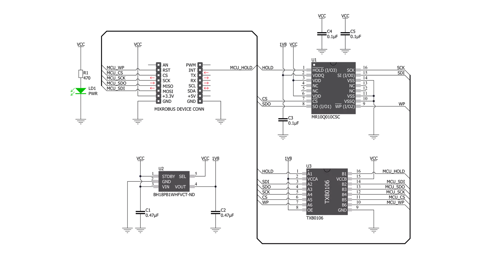
MRAM 2 Click 基于 Everspin Technologies 的 MR10Q010,这是一款 1Mb 四输出高速串行 SPI MRAM 存储解决方案。MR10Q010 是需要快速存储和检索数据和程序的应用的理想存储解决方案,它使用少量引脚、低功耗,并采用节省空间的 16 引脚 SOIC 封装。四个 I/O 在 Quad SPI 模式下允许快速读取和写入,使其成为下一代 RAID 控制器、服务器系统日志、存储设备缓冲区和嵌入式系统数据和程序存储器中传统并行数据总线接口的有吸引力的替代方案。此 Click board™ 包含 Rohm Semiconductor 的 LDO 稳压器 BH18PB1WHFVCT 提供 1.8V 电源电压。当
应用在待机状态下运行时,LDO 通过将电流消耗降低到大约 2μA 来降低功耗。在正常电流操作期间,它会自动切换到高速操作模式。LDO 稳压器输出为德州仪器的 TXB0106 提供所需的参考电压,TXB0106 是一种具有自动方向感应的 6 位双向电平转换和电压翻译器。电平转换器另一侧的参考电压取自 mikroBUS™ 的 3.3V 引脚。MRAM 2 Click 使用支持 SPI 模式 0 和 3 的标准 SPI 串行接口与 MCU 通信,工作时钟频率高达 104 MHz。它还支持 Quad Peripheral Interface (QPI) 和 Quad SPI 模式,组织为 131.072 个 8 位字。读写操作可以在存储器中随机发生,写入之间没有延迟。
MR10Q010 使用连接到 mikroBUS™ 上 RST 引脚的写保护信号来防止对状态寄存器的写操作,而连接到 mikroBUS™ 上 INT 引脚的 HOLD 信号用于中断内存操作以执行其他任务。当 HOLD 为低电平时,当前操作暂停。此 Click Board™ 设计为仅在 3.3V 逻辑电平下运行。在使用具有不同逻辑电平的 MCU 之前,应进行适当的逻辑电压电平转换。有关 MR10Q010 的更多信息,请参阅附带的数据手册。此外,该 Click board™ 配备了一个包含易于使用的功能和示例代码的库,可以用作进一步开发的参考。


功能概述
开发板
Clicker 2 for Kinetis 是一款紧凑型入门开发板,它将 Click 板™的灵活性带给您喜爱的微控制器,使其成为实现您想法的完美入门套件。它配备了一款板载 32 位 ARM Cortex-M4F 微控制器,NXP 半导体公司的 MK64FN1M0VDC12,两个 mikroBUS™ 插槽用于 Click 板™连接,一个 USB 连接器,LED 指示灯,按钮,一个 JTAG 程序员连接器以及两个 26 针头用于与外部电子设备的接口。其紧凑的设计和清晰、易识别的丝网标记让您能够迅速构建具有独特功能和特性
的小工具。Clicker 2 for Kinetis 开发套件的每个部分 都包含了使同一板块运行最高效的必要组件。除了可以选择 Clicker 2 for Kinetis 的编程方式,使用 USB HID mikroBootloader 或外部 mikroProg 连接器进行 Kinetis 编程外,Clicker 2 板还包括一个干净且调节过的开发套件电源供应模块。它提供了两种供电方式;通过 USB Micro-B 电缆,其中板载电压调节器为板上每个组件提供适当的电压水平,或使用锂聚合物 电池通过板载电池连接器供电。所有 mikroBUS™ 本
身支持的通信方法都在这块板上,包括已经建立良好的 mikroBUS™ 插槽、重置按钮和几个用户可配置的按钮及 LED 指示灯。Clicker 2 for Kinetis 是 Mikroe 生态系统的一个组成部分,允许您在几分钟内创建新的应用程序。它由 Mikroe 软件工具原生支持,得益于大量不同的 Click 板™(超过一千块板),其数量每天都在增长,它涵盖了原型制作的许多方面。

微控制器概述
MCU卡片 / MCU

建筑
ARM Cortex-M4
MCU 内存 (KB)
1024
硅供应商
NXP
引脚数
121
RAM (字节)
262144
使用的MCU引脚
mikroBUS™映射器
“仔细看看!”
Click board™ 原理图
一步一步来
项目组装

从选择您的开发板和Click板™开始。以Clicker 2 for Kinetis作为您的开发板开始。


实时跟踪您的结果
应用程序输出
1. 应用程序输出 - 在调试模式下,“应用程序输出”窗口支持实时数据监控,直接提供执行结果的可视化。请按照提供的教程正确配置环境,以确保数据正确显示。

2. UART 终端 - 使用UART Terminal通过USB to UART converter监视数据传输,实现Click board™与开发系统之间的直接通信。请根据项目需求配置波特率和其他串行设置,以确保正常运行。有关分步设置说明,请参考提供的教程。

3. Plot 输出 - Plot功能提供了一种强大的方式来可视化实时传感器数据,使趋势分析、调试和多个数据点的对比变得更加直观。要正确设置,请按照提供的教程,其中包含使用Plot功能显示Click board™读数的分步示例。在代码中使用Plot功能时,请使用以下函数:plot(insert_graph_name, variable_name);。这是一个通用格式,用户需要将“insert_graph_name”替换为实际图表名称,并将“variable_name”替换为要显示的参数。

软件支持
库描述
该库包含 MRAM 2 Click 驱动程序的 API。
关键功能:
mram2_wren- 写使能功能mram2_read- 读取数据字节功能mram2_write- 写入数据字节功能
开源
代码示例
完整的应用程序代码和一个现成的项目可以通过NECTO Studio包管理器直接安装到NECTO Studio。 应用程序代码也可以在MIKROE的GitHub账户中找到。
/*!
 * \file
 * \brief Mram2 Click example
 *
 * # Description
 * This example demonstrates the use of MRAM 2 Click board.
 *
 * The demo application is composed of two sections :
 *
 * ## Application Init
 * Initializes the driver, sets the write protect and disables the hold signal.
 *
 * ## Application Task
 * Writes "MikroE" into the first 6 memory locations, and then reads it back
 * and displays it to the USB UART approximately every 5 seconds.
 *
 * \author MikroE Team
 *
 */
// ------------------------------------------------------------------- INCLUDES

#include "board.h"
#include "log.h"
#include "mram2.h"

// ------------------------------------------------------------------ VARIABLES

static mram2_t mram2;
static log_t logger;

char val_in[ 7 ] = { 'M', 'i', 'k', 'r', 'o', 'E', 0 };
char val_out[ 7 ] = { 0 };

// ------------------------------------------------------ APPLICATION FUNCTIONS

void application_init ( void )
{
    log_cfg_t log_cfg;
    mram2_cfg_t cfg;

    /**
     * Logger initialization.
     * Default baud rate: 115200
     * Default log level: LOG_LEVEL_DEBUG
     * @note If USB_UART_RX and USB_UART_TX
     * are defined as HAL_PIN_NC, you will
     * need to define them manually for log to work.
     * See @b LOG_MAP_USB_UART macro definition for detailed explanation.
     */
    LOG_MAP_USB_UART( log_cfg );
    log_init( &logger, &log_cfg );
    log_info( &logger, "---- Application Init ----" );

    //  Click initialization.

    mram2_cfg_setup( &cfg );
    MRAM2_MAP_MIKROBUS( cfg, MIKROBUS_1 );
    mram2_init( &mram2, &cfg );

    log_printf( &logger, "------------------- \r\n" );
    log_printf( &logger, "   MRAM 2 Click     \r\n" );
    log_printf( &logger, "------------------- \r\n" );
    mram2_write_protect( &mram2, MRAM2_WP_ENABLE );
    mram2_hold( &mram2, MRAM2_HLD_DISABLE );
    log_printf( &logger, "   Initialized      \r\n" );
    log_printf( &logger, "------------------- \r\n" );
    Delay_ms ( 100 );
}

void application_task ( void )
{
    mram2_wren( &mram2 );
    log_printf( &logger, "Write enabled!\r\n" );
    Delay_ms ( 100 );
    log_printf( &logger, "Writing \"%s\" to memory...\r\n", val_in );
    mram2_write( &mram2, 0x000000, &val_in[ 0 ], 6 );
    Delay_ms ( 100 );
    mram2_wrdi ( &mram2 );
    log_printf( &logger, "Write disabled!\r\n" );
    Delay_ms ( 100 );
    mram2_read ( &mram2, 0x000000, &val_out[ 0 ], 6 );
    log_printf( &logger, "Read data : %s\r\n", val_out );

    log_printf( &logger, "-------------------\r\n" );
    Delay_ms ( 1000 );
    Delay_ms ( 1000 );
    Delay_ms ( 1000 );
    Delay_ms ( 1000 );
    Delay_ms ( 1000 );
}

int main ( void )
{
    /* Do not remove this line or clock might not be set correctly. */
    #ifdef PREINIT_SUPPORTED
    preinit();
    #endif

    application_init( );

    for ( ; ; )
    {
        application_task( );
    }

    return 0;
}

// ------------------------------------------------------------------------ END


