使用AD5142A和PIC32MZ2048EFH100在您的项目中追求完美
告别模拟限制
已发布 6月 24, 2024
点击板
DIGI POT 12 Click
开发板
Flip&Click PIC32MZ
编译器
NECTO Studio
微控制器单元
PIC32MZ2048EFH100
通过我们的数字电位器释放电子电路的最大潜力,达到无与伦比的精度——这是实现每个应用高性能和高效率的关键。
A
A
硬件概览
它是如何工作的?
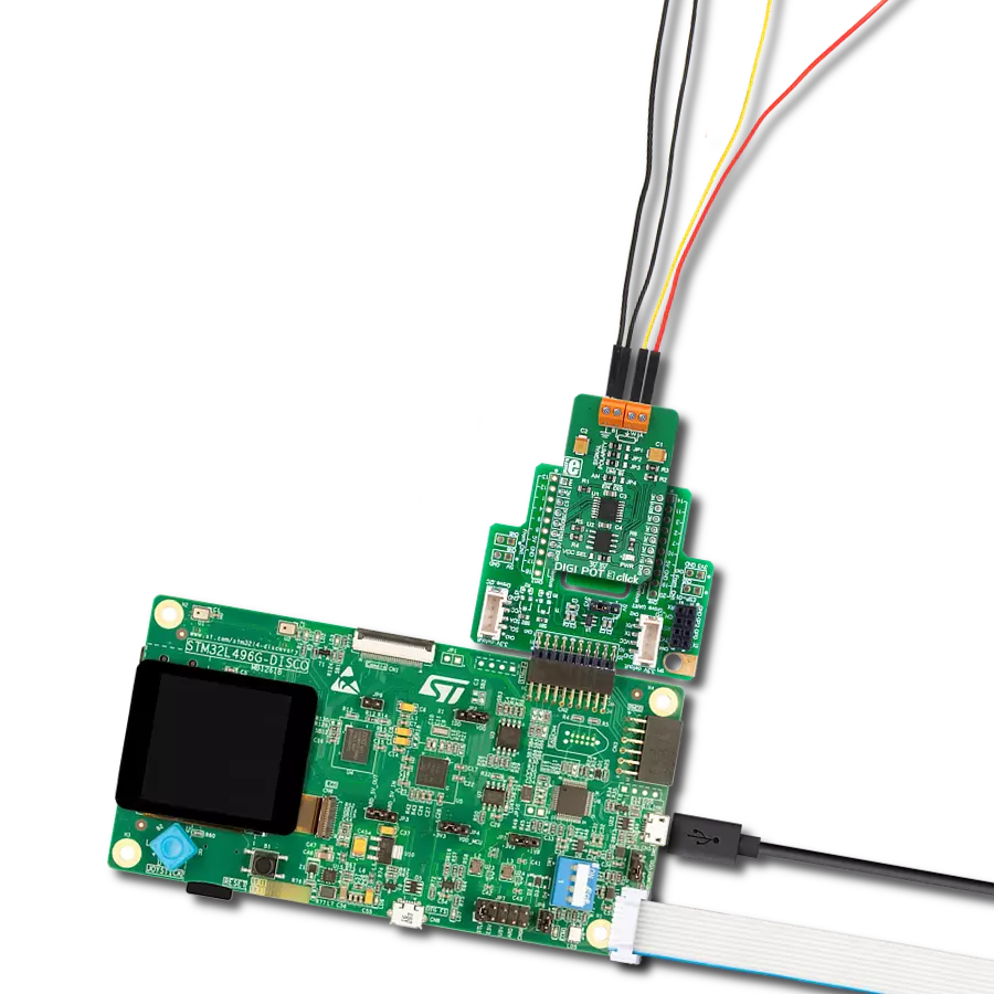
DIGI POT 12 Click基于Analog Devices的AD5142A,这是一款双通道、256位置非易失性数字电位器。电阻滑动触点位置由RDAC寄存器内容决定,该寄存器作为暂存器,允许无限次更改电阻设置。暂存器可以通过标准I2C接口加载16位数据字来编程任何位置设置。RDAC在端子A和端子B之间的标称电阻(RAB)为10KΩ,8位RDAC锁存数据解码以选择256个可能滑动触点设置中的一个。当找到所需位置时,可以将该值存储在板载EEPROM存储器中,从而在后续上电时始终恢复滑动触点位置。
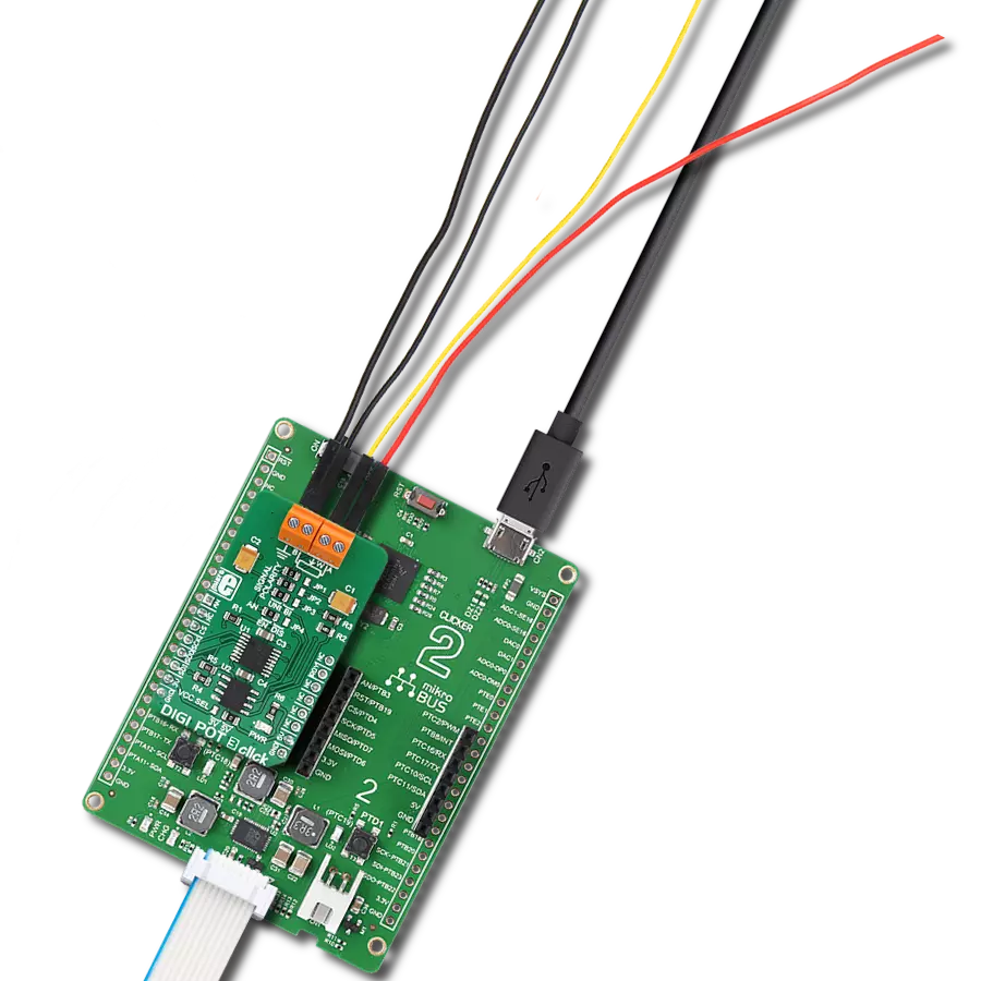
EEPROM数据可以独立读取、写入并通过软件保护。该Click板™通过标准双线I2C接口与MCU通信,并以标准(100KHz)和快速(400KHz)数据传输模式运行。I2C地址可以通过默认设置为0的ADDR SEL跳线选择。还有一个RST引脚用于从EEPROM重置数字电位器的RDAC寄存器,低电平有效。此外,该Click板™带有INDEP SEL跳线,允许选择电位器模式和线性增益设置模式,默认设置为电位器模式(0)。线性增益设置模式可以将电位器控制为两个连接在单点的独立变阻器。一旦设置跳
线,软件不能将其关闭。此外,还有突发模式,可以将多个数据字节发送到主机MCU。关断模式将RDAC置于零功耗状态,而EEPROM中的数据保持不变。B、W和A端子之间没有极性限制,但它们不能高于VCC(最大5V)或低于VSS(0V)。该Click板™可以通过VCC SEL跳线选择使用3.3V或5V逻辑电压电平,从而使3.3V和5V的MCU都能够正确使用通信线路。此外,该Click板™配备了包含易于使用的功能库和示例代码的库,可以作为进一步开发的参考。

功能概述
开发板
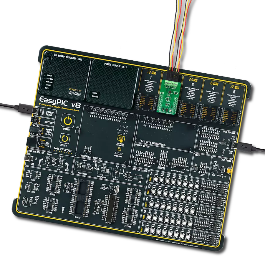
Flip&Click PIC32MZ 是一款紧凑型开发板,设计为一套完整的解决方案,它将 Click 板™的灵活性带给您喜爱的微控制器,使其成为实现您想法的完美入门套件。它配备了一款板载 32 位 PIC32MZ 微控制器,Microchip 的 PIC32MZ2048EFH100,四个 mikroBUS™ 插槽用于 Click 板™连接,两个 USB 连接器,LED 指示灯,按钮,调试器/程序员连接器,以及两个与 Arduino-UNO 引脚兼容的头部。得益于创
新的制造技术,它允许您快速构建具有独特功能和特性的小工具。Flip&Click PIC32MZ 开发套件的每个部分都包含了使同一板块运行最高效的必要组件。此外,还可以选择 Flip&Click PIC32MZ 的编程方式,使用 chipKIT 引导程序(Arduino 风格的开发环境)或我们的 USB HID 引导程序,使用 mikroC、mikroBasic 和 mikroPascal for PIC32。该套件包括一个通过 USB 类型-C(USB-C)连接器的干净且调
节过的电源供应模块。所有 mikroBUS™ 本身支持的 通信方法都在这块板上,包括已经建立良好的 mikroBUS™ 插槽、用户可配置的按钮和 LED 指示灯。Flip&Click PIC32MZ 开发套件允许您在几分钟内创建新的应用程序。它由 Mikroe 软件工具原生支持,得益于大量不同的 Click 板™(超过一千块板),其数量每天都在增长,它涵盖了原型制作的许多方面。

微控制器概述
MCU卡片 / MCU

建筑
PIC32
MCU 内存 (KB)
2048
硅供应商
Microchip
引脚数
100
RAM (字节)
524288
使用的MCU引脚
mikroBUS™映射器
“仔细看看!”
Click board™ 原理图

一步一步来
项目组装

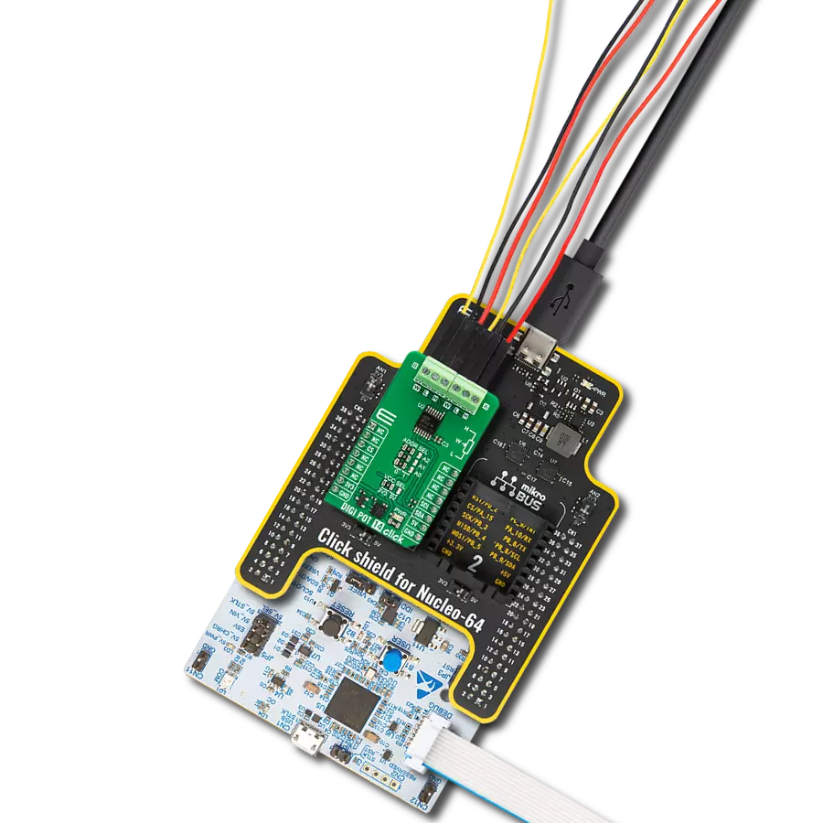
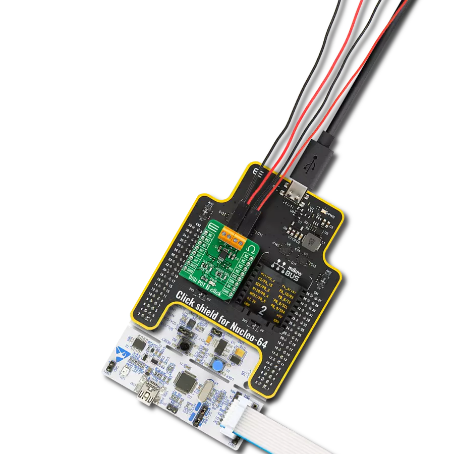
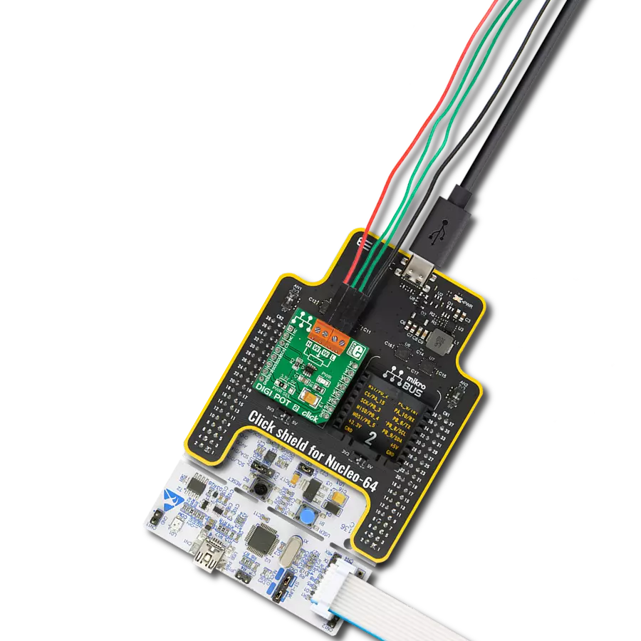
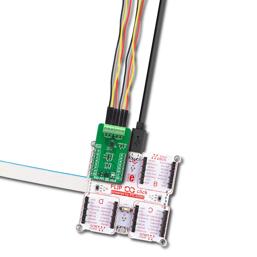
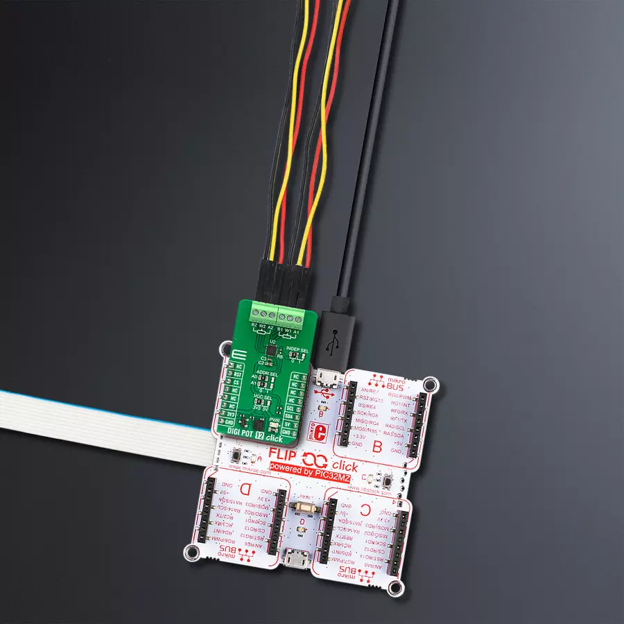
从选择您的开发板和Click板™开始。以Flip&Click PIC32MZ作为您的开发板开始。


软件支持
库描述
该库包含 DIGI POT 12 Click 驱动程序的 API。
关键功能:
digipot12_set_resistance- DIGI POT 12 设置电阻功能。digipot12_get_resistance- DIGI POT 12 获取电阻功能。
开源
代码示例
完整的应用程序代码和一个现成的项目可以通过NECTO Studio包管理器直接安装到NECTO Studio。 应用程序代码也可以在MIKROE的GitHub账户中找到。
/*!
 * @file main.c
 * @brief DIGI POT 12 Click example
 *
 * # Description
 * This library contains API for DIGI POT 12 Click driver.
 * The demo application uses a digital potentiometer
 * to change the resistance values of both channels.
 *
 * The demo application is composed of two sections :
 *
 * ## Application Init
 * The initialization of I2C module, log UART, and additional pins.
 * After the driver init, the app executes a default configuration.
 *
 * ## Application Task
 * This example demonstrates the use of the DIGI POT 12 Click board™.
 * The demo application iterates through the entire wiper range and
 * sets the resistance of both channels in steps of approximately 1kOhm.
 * Results are being sent to the UART Terminal, where you can track their changes.
 *
 * @author Nenad Filipovic
 *
 */

#include "board.h"
#include "log.h"
#include "digipot12.h"

static digipot12_t digipot12;
static log_t logger;

void application_init ( void )
{
    log_cfg_t log_cfg;  /**< Logger config object. */
    digipot12_cfg_t digipot12_cfg;  /**< Click config object. */

    /**
     * Logger initialization.
     * Default baud rate: 115200
     * Default log level: LOG_LEVEL_DEBUG
     * @note If USB_UART_RX and USB_UART_TX
     * are defined as HAL_PIN_NC, you will
     * need to define them manually for log to work.
     * See @b LOG_MAP_USB_UART macro definition for detailed explanation.
     */
    LOG_MAP_USB_UART( log_cfg );
    log_init( &logger, &log_cfg );
    log_info( &logger, " Application Init " );

    // Click initialization.
    digipot12_cfg_setup( &digipot12_cfg );
    DIGIPOT12_MAP_MIKROBUS( digipot12_cfg, MIKROBUS_1 );
    if ( I2C_MASTER_ERROR == digipot12_init( &digipot12, &digipot12_cfg ) )
    {
        log_error( &logger, " Communication init." );
        for ( ; ; );
    }

    if ( DIGIPOT12_ERROR == digipot12_default_cfg ( &digipot12 ) )
    {
        log_error( &logger, " Default configuration." );
        for ( ; ; );
    }

    log_info( &logger, " Application Task " );
    log_printf( &logger, " ----------------------------\r\n" );
    Delay_ms ( 100 );
}

void application_task ( void )
{
    static float res_kohm;
    for ( uint8_t n_cnt = DIGIPOT12_RES_0_KOHM; n_cnt <= DIGIPOT12_RES_10_KOHM; n_cnt++ )
    {
        if ( DIGIPOT12_OK == digipot12_set_resistance( &digipot12, DIGIPOT12_WIPER_SEL_1, ( float ) n_cnt ) )
        {
            if ( DIGIPOT12_OK == digipot12_get_resistance( &digipot12, DIGIPOT12_WIPER_SEL_1, &res_kohm ) )
            {
                log_printf( &logger, " Rwb1 : %.2f kOhm\r\n", res_kohm );
                Delay_ms ( 100 );
            }
        }

        if ( DIGIPOT12_OK == digipot12_set_resistance( &digipot12, DIGIPOT12_WIPER_SEL_2, ( float ) ( DIGIPOT12_RES_10_KOHM - n_cnt ) ) )
        {
            if ( DIGIPOT12_OK == digipot12_get_resistance( &digipot12, DIGIPOT12_WIPER_SEL_2, &res_kohm ) )
            {
                log_printf( &logger, " Rwb2 : %.2f kOhm\r\n", res_kohm );
                Delay_ms ( 100 );
            }
        }
        log_printf( &logger, " ----------------------------\r\n" );
        Delay_ms ( 1000 );
        Delay_ms ( 1000 );
        Delay_ms ( 1000 );
        Delay_ms ( 1000 );
        Delay_ms ( 1000 );
    }
}

int main ( void )
{
    /* Do not remove this line or clock might not be set correctly. */
    #ifdef PREINIT_SUPPORTED
    preinit();
    #endif

    application_init( );

    for ( ; ; )
    {
        application_task( );
    }

    return 0;
}

// ------------------------------------------------------------------------ END