使用TB9051FTG和PIC32MZ2048EFH100实现您的直流电机的静音操作
强大的便携式电机控制

已发布 6月 24, 2024
点击板
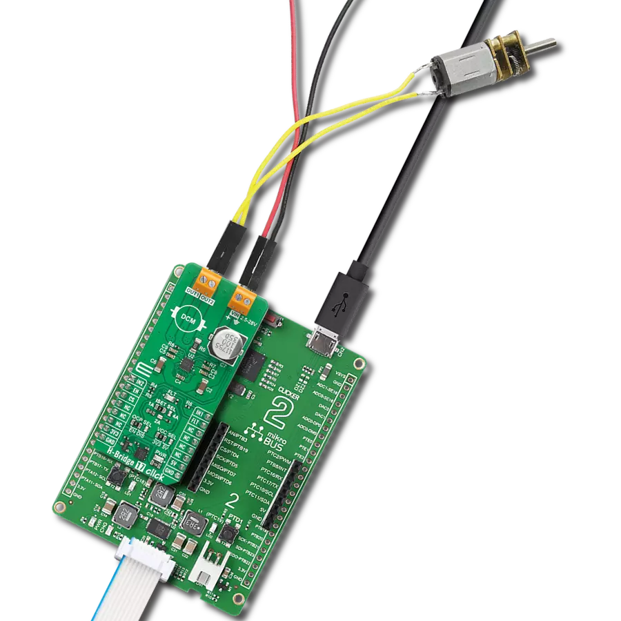
DC Motor 18 Click
开发板
Flip&Click PIC32MZ
编译器
NECTO Studio
微控制器单元
PIC32MZ2048EFH100
优化您的电机,最大限度地提高效率,并充满信心地进行工程设计。拥抱高达5A电流的刷式电机控制!
A
A
硬件概览
它是如何工作的?
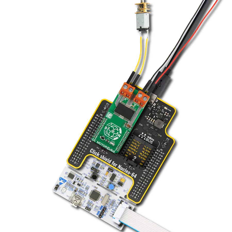
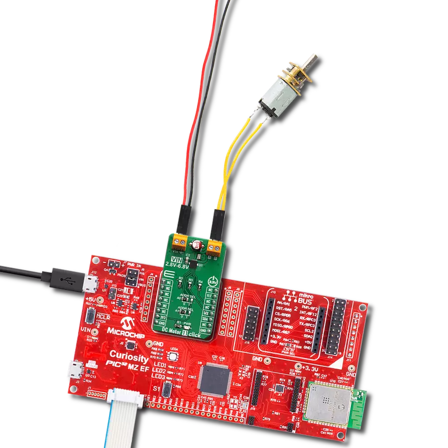
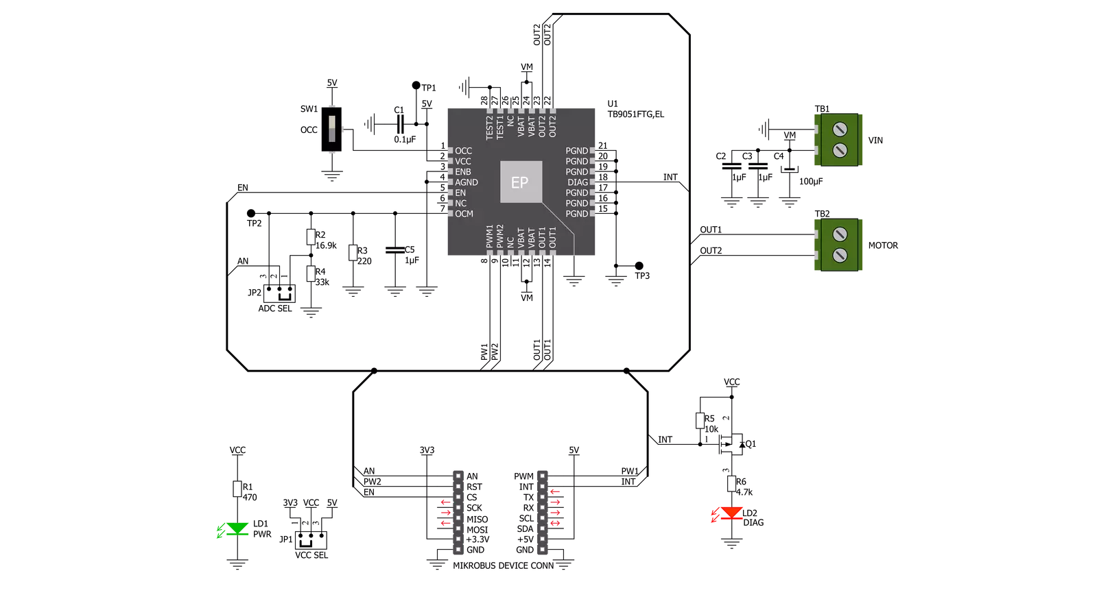
DC Motor 18 Click基于东芝半导体的TB9051FTG,这是一款电机驱动器,集成了用于直接驱动汽车用刷式直流电机的输出驱动器。虽然主要针对车辆发动机应用,如电子油门和阀门控制,但TB9051FTG也可以用于控制最高达5A的车载系统,例如控制后视镜和行李箱锁。控制功能包括与电机相关的(前进、倒车、制动)、PWM控制、电流限制控制、H端电流监视器、诊断输出,以及用于过流、过热和低/高电压的内置检测电路。DC Motor 18 Click使用多个GPIO引脚与MCU通信。使能引脚标记为EN,路由到mikroBUS™插座的CS引脚,可优化功耗,并用于电源开/关(驱动器操作许可)
目的。根据路由到mikroBUS™插座的PWM和RST引脚的PWM控制信号,可以选择前进/倒车/制动模式。实时监视电机驱动输出的H桥中流向高端的电流,用户可以选择电流监视的方式。在5V VCC电源供应的情况下,可以使用mikroBUS™插座上的AN引脚监视电流。在较小的电源(3.3V)情况下,可以通过OCM引脚和GND之间添加的电压分压器进行监视。选择可以通过标记为ADC SEL的板载SMD跳线执行。此Click板™还具有用于异常指示的额外LED。如果检测到诸如过温或过流/欠电压等状态,则通过红色LED(标记为DIAG)指示此类异常,该LED还通过中断INT引脚连接,用户还可以通过该引脚监视诊断引
脚的状态。此外,可以在过流检测时控制电机控制输出,通过标记为OCC的板载开关实现。该开关判断电机控制输出是否为ON(1)或OFF(0)。此板支持为TB9051FTG提供外部电源,可连接到标记为VM的输入端子,在4.5V至28V范围内工作,而直流电机线圈可连接到标记为OUT1和OUT2的端子。此Click板™可以通过VCC SEL跳线选择3.3V或5V逻辑电压级别运行。这样,既支持3.3V又支持5V的MCU可以正确使用通信线路。Click板™配备了一个包含易于使用的函数和示例代码的库,可用作进一步开发的参考。

功能概述
开发板
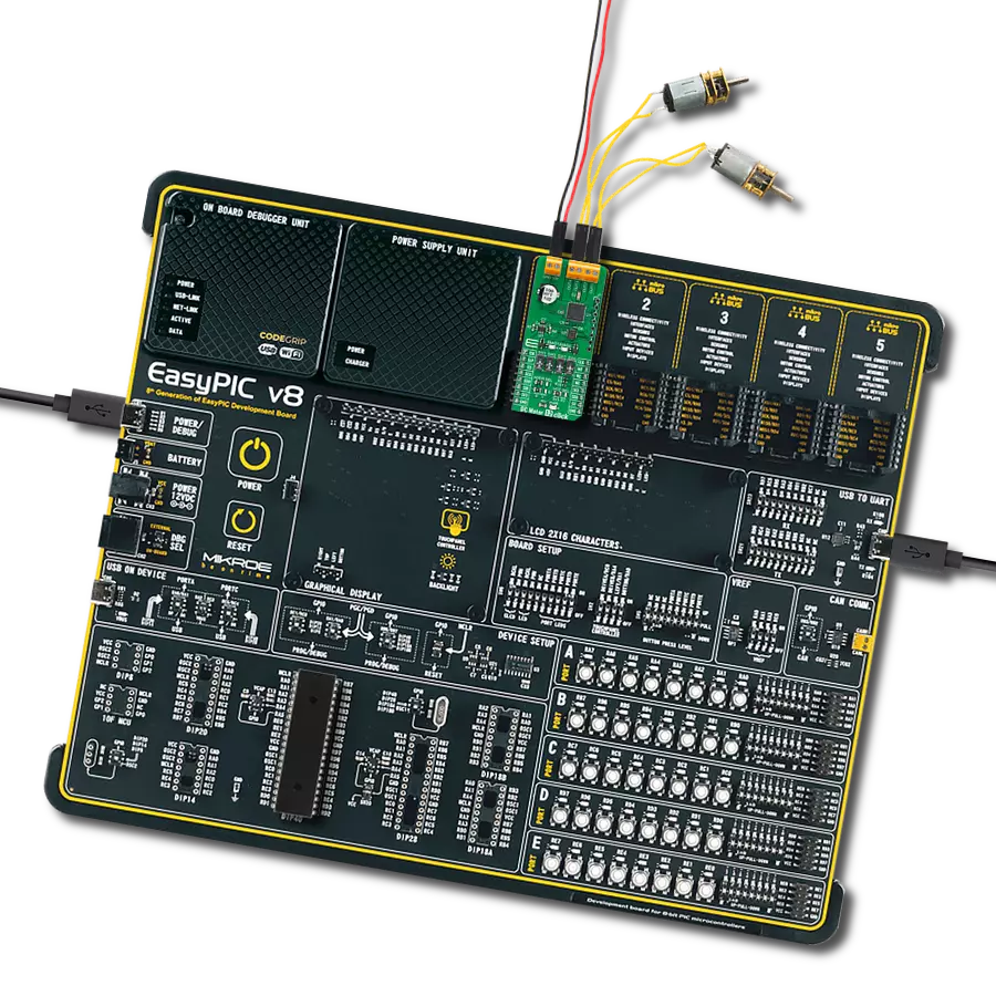
Flip&Click PIC32MZ 是一款紧凑型开发板,设计为一套完整的解决方案,它将 Click 板™的灵活性带给您喜爱的微控制器,使其成为实现您想法的完美入门套件。它配备了一款板载 32 位 PIC32MZ 微控制器,Microchip 的 PIC32MZ2048EFH100,四个 mikroBUS™ 插槽用于 Click 板™连接,两个 USB 连接器,LED 指示灯,按钮,调试器/程序员连接器,以及两个与 Arduino-UNO 引脚兼容的头部。得益于创
新的制造技术,它允许您快速构建具有独特功能和特性的小工具。Flip&Click PIC32MZ 开发套件的每个部分都包含了使同一板块运行最高效的必要组件。此外,还可以选择 Flip&Click PIC32MZ 的编程方式,使用 chipKIT 引导程序(Arduino 风格的开发环境)或我们的 USB HID 引导程序,使用 mikroC、mikroBasic 和 mikroPascal for PIC32。该套件包括一个通过 USB 类型-C(USB-C)连接器的干净且调
节过的电源供应模块。所有 mikroBUS™ 本身支持的 通信方法都在这块板上,包括已经建立良好的 mikroBUS™ 插槽、用户可配置的按钮和 LED 指示灯。Flip&Click PIC32MZ 开发套件允许您在几分钟内创建新的应用程序。它由 Mikroe 软件工具原生支持,得益于大量不同的 Click 板™(超过一千块板),其数量每天都在增长,它涵盖了原型制作的许多方面。

微控制器概述
MCU卡片 / MCU

建筑
PIC32
MCU 内存 (KB)
2048
硅供应商
Microchip
引脚数
100
RAM (字节)
524288
你完善了我!
配件
DC齿轮电机 - 430转/分钟(3-6V)代表了电机和齿轮箱的一体化组合,在此过程中,齿轮的添加导致了电机速度的降低,同时增加了扭矩输出。这种齿轮电机具有斜齿轮箱,使其成为对扭矩和速度要求较低的应用具有高度可靠性的解决方案。齿轮电机的最关键参数是速度、扭矩和效率,在这种情况下,无负载时的速度为520转/分钟,最大效率时为430转/分钟,电流为60mA,扭矩为50g.cm。额定为3-6V操作电压范围和顺时针/逆时针旋转方向,这种电机代表了在机器人技术、医疗设备、电动门锁等领域中初始由刷式直流电机执行的许多功能的出色解决方案。

使用的MCU引脚
mikroBUS™映射器
“仔细看看!”
Click board™ 原理图
一步一步来
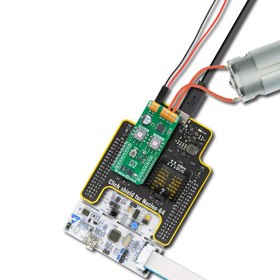
项目组装

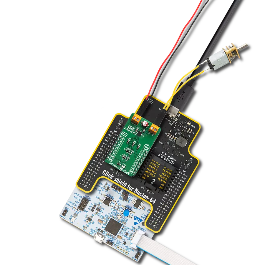
从选择您的开发板和Click板™开始。以Flip&Click PIC32MZ作为您的开发板开始。


软件支持
库描述
该库包含 DC Motor 18 Click 驱动程序的 API。
关键功能:
dcmotor18_set_speed_percentage- 设置速度输出百分比dcmotor18_set_enable- 设置使能引脚状态dcmotor18_read_an_pin_current- 读取AN引脚电流
开源
代码示例
完整的应用程序代码和一个现成的项目可以通过NECTO Studio包管理器直接安装到NECTO Studio。 应用程序代码也可以在MIKROE的GitHub账户中找到。
/*!
 * @file main.c
 * @brief DCMotor18 Click example
 *
 * # Description
 * This example application showcases ability of Click
 * board to control DC motors using PWM modulation in
 * both directions and different speeds.
 *
 * The demo application is composed of two sections :
 *
 * ## Application Init
 * Initialization of MCU communication modules (PWM, ADC, UART)
 * and additioal gpio for control of the device. Then sets
 * default configuration that enables device to control the DC motor.
 *
 * ## Application Task
 * Drives motor in one direction from 0 to 100% of the speed using
 * PWM, and then returns it back to 0. Then changes the rotation
 * direction and repeats the process of increasing and decreasing
 * acceleration.
 *
 * @author Luka Filipovic
 *
 */

#include "board.h"
#include "log.h"
#include "dcmotor18.h"

static dcmotor18_t dcmotor18;
static log_t logger;

void application_init ( void )
{
    log_cfg_t log_cfg;  /**< Logger config object. */
    dcmotor18_cfg_t dcmotor18_cfg;  /**< Click config object. */

    /**
     * Logger initialization.
     * Default baud rate: 115200
     * Default log level: LOG_LEVEL_DEBUG
     * @note If USB_UART_RX and USB_UART_TX
     * are defined as HAL_PIN_NC, you will
     * need to define them manually for log to work.
     * See @b LOG_MAP_USB_UART macro definition for detailed explanation.
     */
    LOG_MAP_USB_UART( log_cfg );
    log_init( &logger, &log_cfg );
    log_info( &logger, " Application Init " );

    // Click initialization.
    dcmotor18_cfg_setup( &dcmotor18_cfg );
    DCMOTOR18_MAP_MIKROBUS( dcmotor18_cfg, MIKROBUS_1 );
    err_t init_flag  = dcmotor18_init( &dcmotor18, &dcmotor18_cfg );
    if ( PWM_ERROR == init_flag )
    {
        log_error( &logger, " Application Init Error. " );
        log_info( &logger, " Please, run program again... " );

        for ( ; ; );
    }

    dcmotor18_default_cfg ( &dcmotor18 );

    log_info( &logger, " Application Task " );
    Delay_ms ( 500 );
}

void application_task ( void )
{
    static int8_t duty_cnt = 1;
    static int8_t duty_inc = 1;
    float speed = duty_cnt / 10.0;
    static uint8_t direction = 1;

    dcmotor18_set_direction( &dcmotor18, direction );
    dcmotor18_set_speed_percentage ( &dcmotor18, speed );

    if ( dcmotor18.direction )
    {
        log_printf( &logger, "<<< " );
    }
    else
    {
        log_printf( &logger, ">>> " );
    }
    log_printf( &logger, "Speed: %d%%\r\n", ( uint16_t )( duty_cnt * 10 ) );

    if ( 10 == duty_cnt )
    {
        duty_inc = -1;
    }
    else if ( 0 == duty_cnt )
    {
        duty_inc = 1;
        direction = !direction;
    }
    duty_cnt += duty_inc;

    Delay_ms ( 1000 );
}

int main ( void )
{
    /* Do not remove this line or clock might not be set correctly. */
    #ifdef PREINIT_SUPPORTED
    preinit();
    #endif

    application_init( );

    for ( ; ; )
    {
        application_task( );
    }

    return 0;
}

// ------------------------------------------------------------------------ END
额外支持
资源
类别:有刷