通过使用PT10MV11-103A2020-S和PIC32MZ2048EFM100轻松调整系统的每个方面
微调您的世界:体验微调电位器的精确度

已发布 6月 26, 2024
点击板
POT Click
开发板
Curiosity PIC32 MZ EF
编译器
NECTO Studio
微控制器单元
PIC32MZ2048EFM100
我们致力于为您提供优化设备性能和精度的工具,而我们的微调电位器正是这一承诺的核心。
A
A
硬件概览
它是如何工作的?
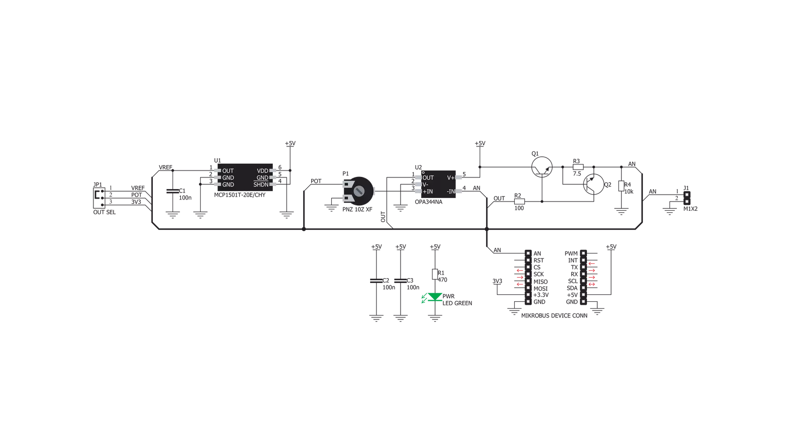
POT Click基于Microchip的MCP1501,这是一款精密电压参考IC,用于提供2.048V的电压。该电压被引导到标记为OUT SEL的小型SMD跳线。通过将跳线移动到REF位置,2.048V将应用于电位器的一端。否则,电位器将连接到mikroBUS™的3.3V轨道。电位器的另一端连接到GND,允许选择0到2.048V范围(VREF)或0到3.3V范围的电压。可调电压可通过mikroBUS™的AN引脚和Click板™上边缘的1x2针头(标记为VOUT)获取。电位器本身标记为PT10MV11-103A2020-S,是Piher Sensing Systems生产的高质量电位器。该公司以其高质量电位器而闻名,广泛应用于各个行
业。电位器具有10 kΩ的碳基电阻表面,是单圈线性电位器,在中间位置时实现50%的电阻。它的直径为10mm。其旋钮未固定:电位器具有带平面表面的孔(六边形),可以插入与之匹配的小杆。这使得可以使用手指和其他精密工具(螺丝刀、六角钥匙等)进行操作。电位器的输出被馈送到德州仪器的OPA344轨到轨单电源运算放大器的非反向输入。该运算放大器是此设计的理想选择,因为它允许轨到轨操作,使用5V单电源,并具有稳定的单位增益。OPA344用作缓冲器,提供恒定的输入和输出阻抗。没有缓冲器,变化的阻抗会影响参考电压。参考电压可以提供不到10 mA的电流,输出电流
超过2 mA时会出现显著的电压下降。因此,OPA344确保电路的良好稳定性。此Click板™的电流输出受输出电路限制,该电路由两个BJT晶体管组成。当输出负载过大时,Q2晶体管的基极-发射极电阻上会出现电压下降,从而开始导通,减少反馈回路上的电压,以这种方式限制最大电流。Q1晶体管用于向输出负载提供足够的电流,防止缓冲器和电路的其余部分受损。因此,在短路情况下,这个晶体管将开始散热。它的尺寸设计能够承受输出上的短路。连接的负载可以汲取高达100mA的电流。

功能概述
开发板
Curiosity PIC32 MZ EF 开发板是一个完全集成的 32 位开发平台,特点是高性能的 PIC32MZ EF 系列(PIC32MZ2048EFM),该系列具有 2MB Flash、512KB RAM、集成的浮点单元(FPU)、加密加速器和出色的连接选项。它包括一个集成的程序员和调试器,无需额外硬件。用户可以通过 MIKROE
mikroBUS™ Click™ 适配器板扩展功能,通过 Microchip PHY 女儿板添加以太网连接功能,使用 Microchip 扩展板添加 WiFi 连接能力,并通过 Microchip 音频女儿板添加音频输入和输出功能。这些板完全集成到 PIC32 强大的软件框架 MPLAB Harmony 中,该框架提供了一个灵活且模块化的接口
来应用开发、一套丰富的互操作软件堆栈(TCP-IP、USB)和易于使用的功能。Curiosity PIC32 MZ EF 开发板提供了扩展能力,使其成为连接性、物联网和通用应用中快速原型设计的绝佳选择。

微控制器概述
MCU卡片 / MCU

建筑
PIC32
MCU 内存 (KB)
2048
硅供应商
Microchip
引脚数
100
RAM (字节)
524288
使用的MCU引脚
mikroBUS™映射器
“仔细看看!”
Click board™ 原理图
一步一步来
项目组装

从选择您的开发板和Click板™开始。以Curiosity PIC32 MZ EF作为您的开发板开始。


实时跟踪您的结果
应用程序输出
1. 应用程序输出 - 在调试模式下,“应用程序输出”窗口支持实时数据监控,直接提供执行结果的可视化。请按照提供的教程正确配置环境,以确保数据正确显示。

2. UART 终端 - 使用UART Terminal通过USB to UART converter监视数据传输,实现Click board™与开发系统之间的直接通信。请根据项目需求配置波特率和其他串行设置,以确保正常运行。有关分步设置说明,请参考提供的教程。

3. Plot 输出 - Plot功能提供了一种强大的方式来可视化实时传感器数据,使趋势分析、调试和多个数据点的对比变得更加直观。要正确设置,请按照提供的教程,其中包含使用Plot功能显示Click board™读数的分步示例。在代码中使用Plot功能时,请使用以下函数:plot(insert_graph_name, variable_name);。这是一个通用格式,用户需要将“insert_graph_name”替换为实际图表名称,并将“variable_name”替换为要显示的参数。

软件支持
库描述
该库包含POT Click驱动程序的 API。
关键功能:
pot_read_an_pin_value- 读取AN引脚AD转换结果的功能pot_read_an_pin_voltage- 读取AN引脚AD转换结果并将其转换为相应电压水平的功能
开源
代码示例
完整的应用程序代码和一个现成的项目可以通过NECTO Studio包管理器直接安装到NECTO Studio。 应用程序代码也可以在MIKROE的GitHub账户中找到。
/*!
 * \file
 * \brief Pot Click example
 *
 * # Description
 * Click board with the accurate selectable reference voltage output.
 *
 * The demo application is composed of two sections :
 *
 * ## Application Init
 * Performs logger and Click initialization.
 *
 * ## Application Task
 * Reads and displays on the USB UART the voltage level measured from AN pin.
 *
 * \author Nemanja Medakovic
 *
 */
// ------------------------------------------------------------------- INCLUDES

#include "board.h"
#include "log.h"
#include "pot.h"

// ------------------------------------------------------------------ VARIABLES

static pot_t pot;
static log_t logger;

// ------------------------------------------------------ APPLICATION FUNCTIONS

void application_init ( void )
{
    log_cfg_t log_cfg;  /**< Logger config object. */
    pot_cfg_t pot_cfg;  /**< Click config object. */

    /**
     * Logger initialization.
     * Default baud rate: 115200
     * Default log level: LOG_LEVEL_DEBUG
     * @note If USB_UART_RX and USB_UART_TX
     * are defined as HAL_PIN_NC, you will
     * need to define them manually for log to work.
     * See @b LOG_MAP_USB_UART macro definition for detailed explanation.
     */
    LOG_MAP_USB_UART( log_cfg );
    log_init( &logger, &log_cfg );
    log_info( &logger, " Application Init " );

    // Click initialization.
    pot_cfg_setup( &pot_cfg );
    POT_MAP_MIKROBUS( pot_cfg, MIKROBUS_1 );
    if ( ADC_ERROR == pot_init( &pot, &pot_cfg ) )
    {
        log_error( &logger, " Communication init." );
        for ( ; ; );
    }

    log_info( &logger, " Application Task " );
}

void application_task ( void )
{
    float voltage = 0;
    if ( POT_OK == pot_read_an_pin_voltage ( &pot, &voltage ) )
    {
        log_printf( &logger, " AN Voltage : %.3f[V]\r\n\n", voltage );
        Delay_ms ( 1000 );
    }
}

int main ( void )
{
    /* Do not remove this line or clock might not be set correctly. */
    #ifdef PREINIT_SUPPORTED
    preinit();
    #endif

    application_init( );

    for ( ; ; )
    {
        application_task( );
    }

    return 0;
}

// ------------------------------------------------------------------------ END


