通过使用WS2812B-2020、EC12D1564402和PIC32MZ2048EFM100创建互动控制、视觉效果和精确位置显示
通过用户友好的旋钮界面传达精确的位置读数

已发布 6月 24, 2024
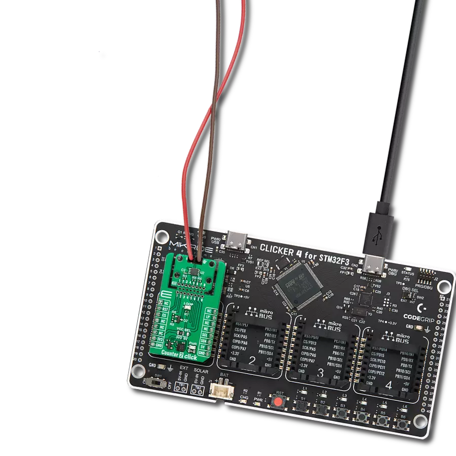
点击板
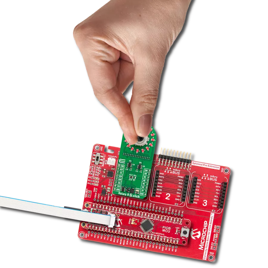
Rotary RGB Click
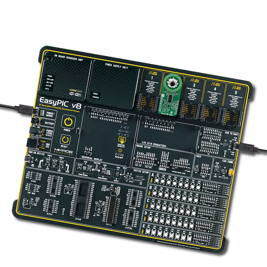
开发板
Curiosity PIC32 MZ EF
编译器
NECTO Studio
微控制器单元
PIC32MZ2048EFM100
适用于需要触觉和视觉反馈的应用,显示编码器设置的位置或水平,如音量控制、位置传感和用户界面控制。
A
A
硬件概览
它是如何工作的?
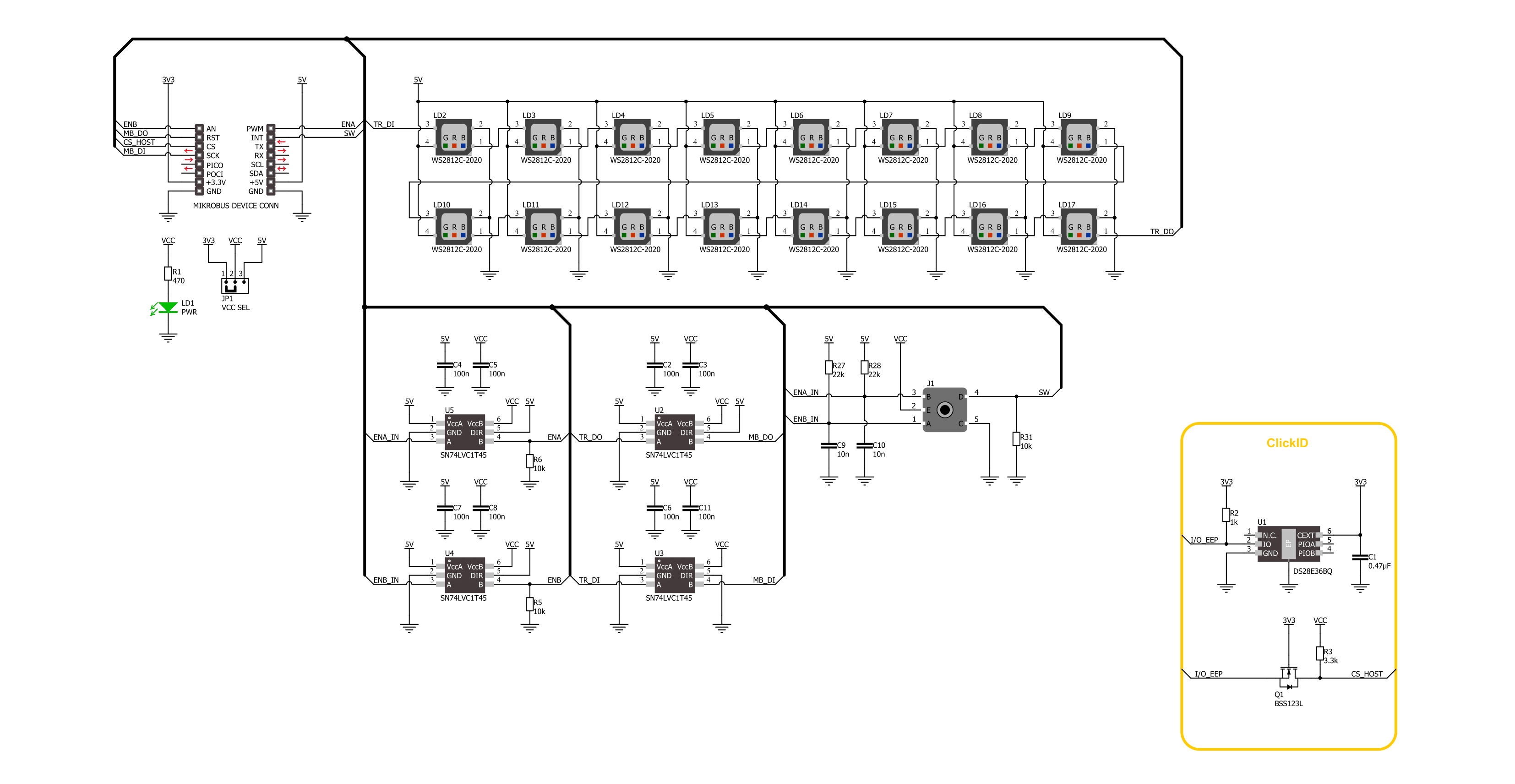
Rotary RGB Click基于由16个单独的RGB LED组成的LED环,这些LED来自Worldsemi的WS2812B-2020,以及高质量的ALPS旋转编码器EC12D1564402,可视化地表示编码器位置和更多功能。WS2812B-2020的内部配置包括智能数字端口数据锁存器和信号重塑放大驱动电路。它还包含一个精密的内部振荡器和一个电压可编程恒流控制部分,确保像素点光颜色高度一致。WS2812B-2020是一种具有低驱动电压(使用来自mikroBUS™电源轨的5V作为主要电源)、环保节能、高亮度、大散射角、良好一致性、低功耗、长寿命等优点的LED。此Click板™是开发各种有趣视觉效果的完美解决方案,适用
于任何应用,如灵活的位置、值指示器等。数据传输协议通过mikroBUS™插座的DO和DI引脚使用单一的NZR通信模式。在像素上电复位序列之后,WS2812B-2020的DI端口从主控制器接收数据;第一个像素收集初始24位数据,然后将其发送到内部数据锁存器,其他由内部信号重塑放大电路重塑的数据通过DO端口发送到下一个级联像素。在每个像素的传输之后,信号减少到24位。像素采用自动重塑传输技术,使像素级联数量不受信号传输的限制,只取决于信号传输的速度。EC12D1564402是一个15脉冲增量旋转编码器,带有一个按钮。该编码器具有独特的机械规格(其内部开关的去抖时间下降到2ms),并
且可以承受高达30,000次的开关循环。支持的去抖电路允许在触发输出之前让接触点稳定。旋转编码器时,它在两个mikroBUS™线上(ENA和ENB引脚)输出A和B信号(相互之间不同相位),并通过mikroBUS™插座的SW引脚输出按钮接触信号。四个德州仪器的SN74LVC1T45单比特总线收发器用于编码器和数据传输协议信号的逻辑电平转换。此Click板™可以通过VCC SEL跳线选择3.3V或5V逻辑电压电平运行。这样,既支持3.3V又支持5V的MCU可以正确使用通信线路。此外,此Click板™配备了一个包含易于使用的功能和示例代码的库,可用作进一步开发的参考。

功能概述
开发板
Curiosity PIC32 MZ EF 开发板是一个完全集成的 32 位开发平台,特点是高性能的 PIC32MZ EF 系列(PIC32MZ2048EFM),该系列具有 2MB Flash、512KB RAM、集成的浮点单元(FPU)、加密加速器和出色的连接选项。它包括一个集成的程序员和调试器,无需额外硬件。用户可以通过 MIKROE
mikroBUS™ Click™ 适配器板扩展功能,通过 Microchip PHY 女儿板添加以太网连接功能,使用 Microchip 扩展板添加 WiFi 连接能力,并通过 Microchip 音频女儿板添加音频输入和输出功能。这些板完全集成到 PIC32 强大的软件框架 MPLAB Harmony 中,该框架提供了一个灵活且模块化的接口
来应用开发、一套丰富的互操作软件堆栈(TCP-IP、USB)和易于使用的功能。Curiosity PIC32 MZ EF 开发板提供了扩展能力,使其成为连接性、物联网和通用应用中快速原型设计的绝佳选择。

微控制器概述
MCU卡片 / MCU

建筑
PIC32
MCU 内存 (KB)
2048
硅供应商
Microchip
引脚数
100
RAM (字节)
524288
使用的MCU引脚
mikroBUS™映射器
“仔细看看!”
Click board™ 原理图
一步一步来
项目组装

从选择您的开发板和Click板™开始。以Curiosity PIC32 MZ EF作为您的开发板开始。


实时跟踪您的结果
应用程序输出
1. 应用程序输出 - 在调试模式下,“应用程序输出”窗口支持实时数据监控,直接提供执行结果的可视化。请按照提供的教程正确配置环境,以确保数据正确显示。

2. UART 终端 - 使用UART Terminal通过USB to UART converter监视数据传输,实现Click board™与开发系统之间的直接通信。请根据项目需求配置波特率和其他串行设置,以确保正常运行。有关分步设置说明,请参考提供的教程。

3. Plot 输出 - Plot功能提供了一种强大的方式来可视化实时传感器数据,使趋势分析、调试和多个数据点的对比变得更加直观。要正确设置,请按照提供的教程,其中包含使用Plot功能显示Click board™读数的分步示例。在代码中使用Plot功能时,请使用以下函数:plot(insert_graph_name, variable_name);。这是一个通用格式,用户需要将“insert_graph_name”替换为实际图表名称,并将“variable_name”替换为要显示的参数。

软件支持
库描述
该库包含 Rotary RGB Click 驱动程序的 API。
关键功能:
rotaryrgb_set_led_pos_color- 此函数为选定的LED位置设置所需的颜色。rotaryrgb_set_all_leds_data- 此函数使用GPIO协议写入16个元素的数据数组以控制所有LED。rotaryrgb_get_state_switch- 此函数返回旋转编码器开关信号,即SW(INT)引脚的状态。
开源
代码示例
完整的应用程序代码和一个现成的项目可以通过NECTO Studio包管理器直接安装到NECTO Studio。 应用程序代码也可以在MIKROE的GitHub账户中找到。
/*!
 * @file main.c
 * @brief Rotary RGB Click Example.
 *
 * # Description
 * This library contains the API for the Rotary RGB Click driver
 * to control LEDs states and a rotary encoder position readings.
 *
 * The demo application is composed of two sections :
 *
 * ## Application Init
 * Initialization of GPIO module and log UART.
 * After the driver init, the app turn off all LEDs.
 *
 * ## Application Task
 * This example demonstrates the use of the Rotary RGB Click board.
 * The demo example shows the functionality of a rotary encoder used to control RGB LEDs.
 * The switch controls the application of the colors,
 * and the encoder mechanism controls the state of the LEDs.
 *
 * ## Additional Function
 * - static void rotaryrgb_logic_zero ( void )
 * - static void rotaryrgb_logic_one ( void )
 * - static void rotaryrgb_switch_detection ( void )
 * - static void rotaryrgb_encoder_mechanism ( void )
 *
 * @note
 * Make sure the logic delays are defined for your system in the rotaryrgb_delays.h file.
 *
 * @author Nenad Filipovic
 *
 */

#include "board.h"
#include "log.h"
#include "rotaryrgb.h"
#include "rotaryrgb_delays.h"

static rotaryrgb_t rotaryrgb;   /**< Rotary RGB Click driver object. */
static log_t logger;            /**< Logger object. */

static uint8_t start_rot_status = 0;
static uint8_t led_color_sel = 0;
static uint8_t old_state = 0;
static uint8_t new_state = 1;
static uint8_t old_rot_state = 0;
static uint8_t new_rot_state = 1;
static uint16_t led_pos = 1;
static uint32_t demo_color_table[ 8 ] =
{
    ROTARYRGB_COLOR_WHITE_50,
    ROTARYRGB_COLOR_RED_50,
    ROTARYRGB_COLOR_GREEN_50,
    ROTARYRGB_COLOR_BLUE_50,
    ROTARYRGB_COLOR_LIGHT_BLUE_50,
    ROTARYRGB_COLOR_YELLOW_50,
    ROTARYRGB_COLOR_PURPLE_50,
    ROTARYRGB_COLOR_OFF
};

/**
 * @brief Rotary RGB logic zero function.
 * @details This function generates a logic zero sequence char
 * to control the LED light source.
 * @return Nothing.
 */
static void rotaryrgb_logic_zero ( void );

/**
 * @brief Rotary RGB logic one function.
 * @details This function generates a logic one sequence char
 * to control the LED light source.
 * @return Nothing.
 */
static void rotaryrgb_logic_one ( void );

/**
 * @brief Rotary RGB switch detection function.
 * @details This function is used for the switch state detection.
 * @return Nothing.
 */
static void rotaryrgb_switch_detection ( void );

/**
 * @brief Rotary RGB encoder mechanism function.
 * @details This function is used to control the state of the LEDs
 * by detecting the rotation direction of the rotary encoder.
 * @return Nothing.
 */
static void rotaryrgb_encoder_mechanism ( void );

void application_init ( void )
{
    log_cfg_t log_cfg;  /**< Logger config object. */
    rotaryrgb_cfg_t rotaryrgb_cfg;  /**< Click config object. */

    /**
     * Logger initialization.
     * Default baud rate: 115200
     * Default log level: LOG_LEVEL_DEBUG
     * @note If USB_UART_RX and USB_UART_TX
     * are defined as HAL_PIN_NC, you will
     * need to define them manually for log to work.
     * See @b LOG_MAP_USB_UART macro definition for detailed explanation.
     */
    LOG_MAP_USB_UART( log_cfg );
    log_init( &logger, &log_cfg );
    log_info( &logger, " Application Init " );

    // Click initialization.
    rotaryrgb_cfg_setup( &rotaryrgb_cfg, &rotaryrgb_logic_zero, &rotaryrgb_logic_one );
    ROTARYRGB_MAP_MIKROBUS( rotaryrgb_cfg, MIKROBUS_1 );
    if ( DIGITAL_OUT_UNSUPPORTED_PIN == rotaryrgb_init( &rotaryrgb, &rotaryrgb_cfg ) )
    {
        log_error( &logger, " Communication init." );
        for ( ; ; );
    }

    rotaryrgb_set_all_led_color( &rotaryrgb, ROTARYRGB_COLOR_OFF );
    Delay_ms ( 100 );

    log_info( &logger, " Application Task " );
    Delay_ms ( 100 );
}

void application_task ( void )
{
    rotaryrgb_set_led_pos_color( &rotaryrgb, led_pos % 17, demo_color_table[ led_color_sel ] );
    rotaryrgb_switch_detection( );
    rotaryrgb_encoder_mechanism( );
}

int main ( void )
{
    /* Do not remove this line or clock might not be set correctly. */
    #ifdef PREINIT_SUPPORTED
    preinit();
    #endif

    application_init( );

    for ( ; ; )
    {
        application_task( );
    }

    return 0;
}

static void rotaryrgb_logic_zero ( void )
{
    hal_ll_gpio_set_pin_output( &rotaryrgb.di_pin.pin );
    DELAY_TOH;
    hal_ll_gpio_clear_pin_output( &rotaryrgb.di_pin.pin );
    DELAY_TOL;
}

static void rotaryrgb_logic_one ( void )
{
    hal_ll_gpio_set_pin_output( &rotaryrgb.di_pin.pin );
    DELAY_T1H;
    hal_ll_gpio_clear_pin_output( &rotaryrgb.di_pin.pin );
    DELAY_T1L;
}

static void rotaryrgb_switch_detection ( void )
{
    if ( rotaryrgb_get_state_switch( &rotaryrgb ) )
    {
        new_state = 1;
        if ( ( 1 == new_state ) && ( 0 == old_state ) )
        {
            old_state = 1;
            led_color_sel++;
            if ( 7 < led_color_sel )
            {
                led_color_sel = 0;
            }
        }
    }
    else
    {
        old_state = 0;
    }
}

static void rotaryrgb_encoder_mechanism ( void )
{
    if ( rotaryrgb_get_state_enb( &rotaryrgb ) == rotaryrgb_get_state_ena( &rotaryrgb ) )
    {
        old_rot_state = 0;
        start_rot_status = rotaryrgb_get_state_enb( &rotaryrgb ) && rotaryrgb_get_state_ena( &rotaryrgb );
    }
    else
    {
        new_rot_state = 1;
        if ( new_rot_state != old_rot_state )
        {
            old_rot_state = 1;
            if ( start_rot_status != rotaryrgb_get_state_enb( &rotaryrgb ) )
            {
                led_pos++;
            }
            else
            {
                led_pos--;
            }

            if ( 0 == led_pos % 17 )
            {
                Delay_ms ( 1 );
                rotaryrgb_set_all_led_color( &rotaryrgb, ROTARYRGB_COLOR_OFF );
            }
        }
    }
}

// ------------------------------------------------------------------------ END
额外支持
资源
类别:旋转编码器