使用 RFM75 和 PIC18F25K40 建立长距离无线传输
轻松保持连接
已发布 6月 24, 2024
点击板
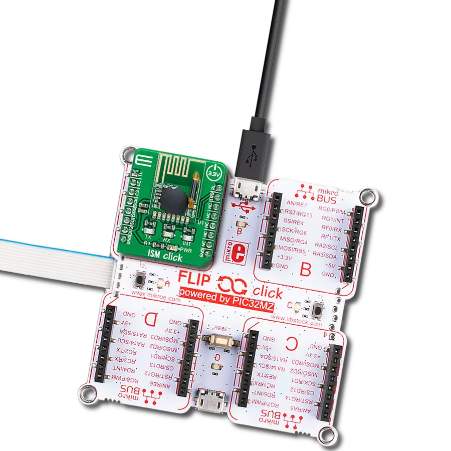
ISM Click
开发板
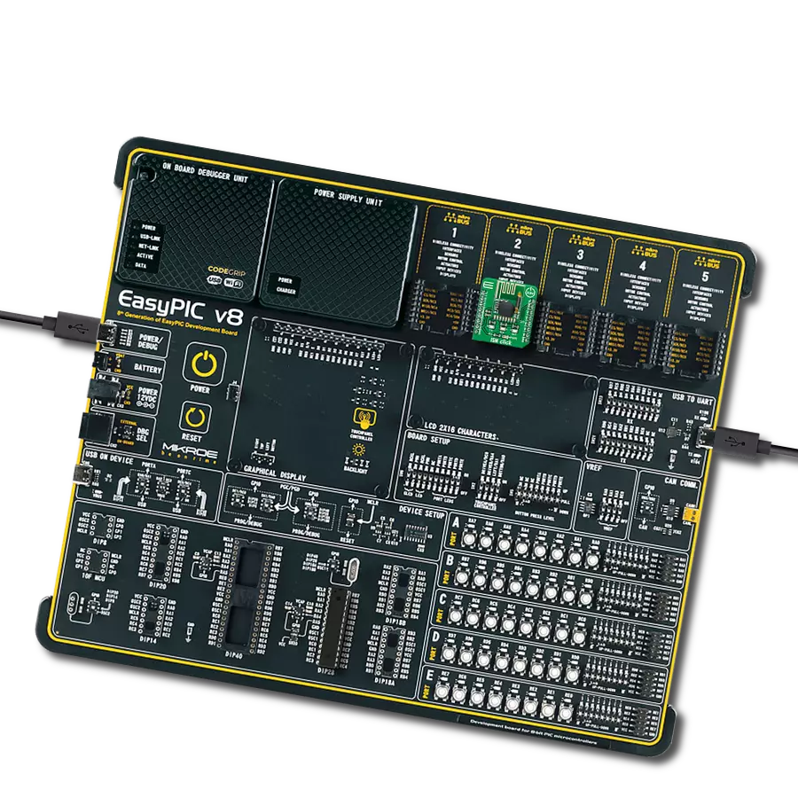
EasyPIC v8
编译器
NECTO Studio
微控制器单元
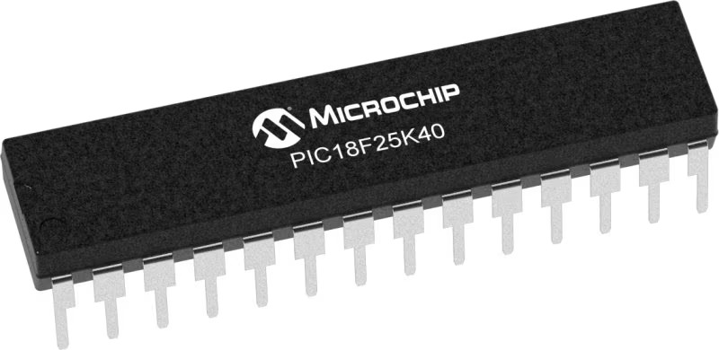
PIC18F25K40
释放您解决方案的潜力,实现高效、快速和可靠的无线通信。
A
A
硬件概览
它是如何工作的?
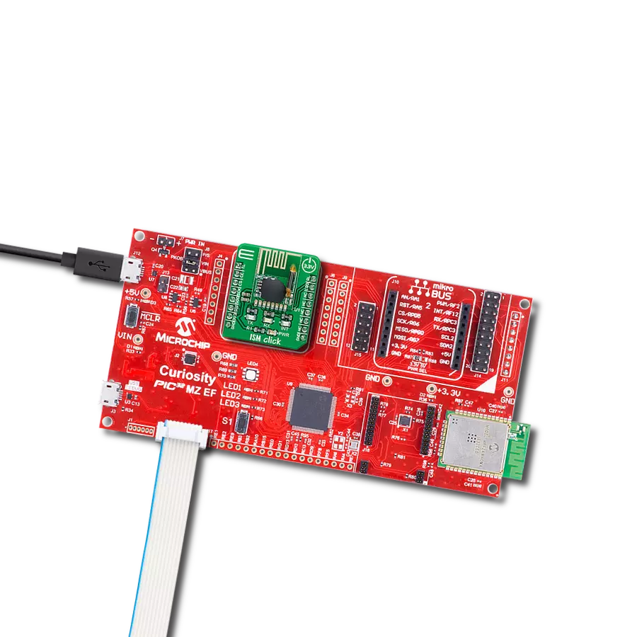
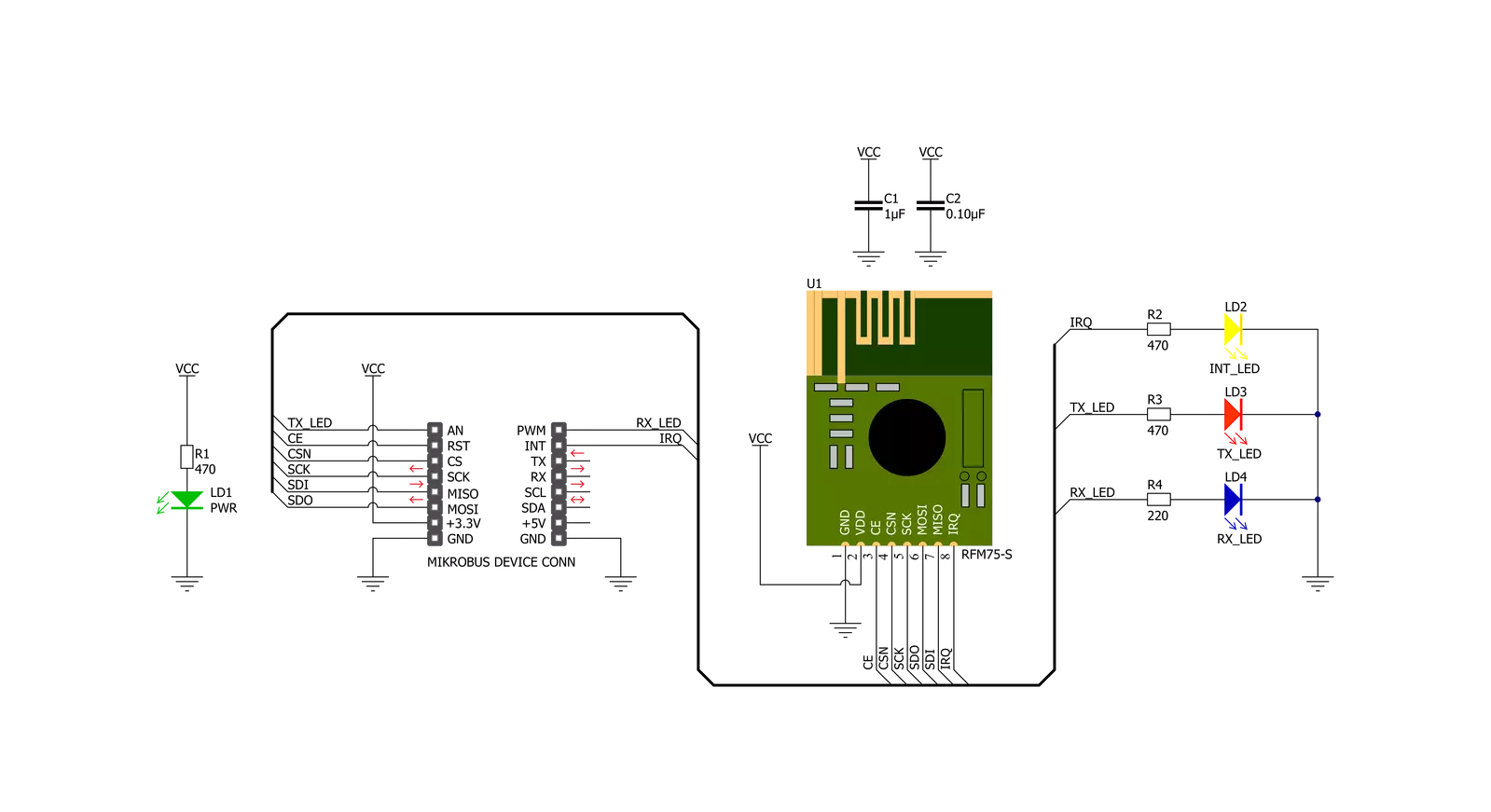
ISM Click基于RF Solutions的RFM75,这是一款低功耗、高性能的2.4GHz GFSK收发器,工作在全球ISM频段2400MHz至2527MHz。RFM75以TDD模式运行,可作为发射机或接收机。突发模式传输和高达2Mbps的空中数据速率使其适用于超低功耗应用。嵌入式数据包处理引擎使得整个操作只需一个简单的MCU作为无线电系统。自动重传和自动确认功能可在没有任何MCU干预的情况下提供可靠的链路。发射机和接收机必须使用相同的RF信道频率进行通信,支持可编程的空中数据速率为250Kbps、1Mbps或2Mbps。RF信道频率
决定了RFM75使用的信道的中心。RF_CH寄存器在寄存器组0中设置频率,按照以下公式计算F0= 2400 + RF_CH(MHz),其中RF信道频率的分辨率为1MHz。ISM Click通过标准SPI串行接口与MCU通信,该接口的工作时钟速率可高达8 MHz。在省电模式下,RFM75处于睡眠模式,功耗极低。在此模式下,SPI接口仍然活动,通过SPI接口可访问所有寄存器值。此外,此Click板上还有一个黄色LED指示灯,路由到mikroBUS™插座的INT引脚上(在成功接收数据包后为用户提供反馈),以及一个芯片使能功能,路由到mikroBUS™插座
的RST引脚上,用于激活RFM75的TX或RX模式。此外,它还有两个额外的LED指示灯,一个红色和一个蓝色LED,路由到mikroBUS™插座的AN和PWM引脚上。用户可以在发送或接收数据时使用它进行可视指示。此Click板™只能使用3.3V逻辑电压电平操作。在使用具有不同逻辑电平的MCU之前,必须对板上执行适当的逻辑电压电平转换。但是,该Click板™配备了一个包含函数和示例代码的库,可用作进一步开发的参考。


功能概述
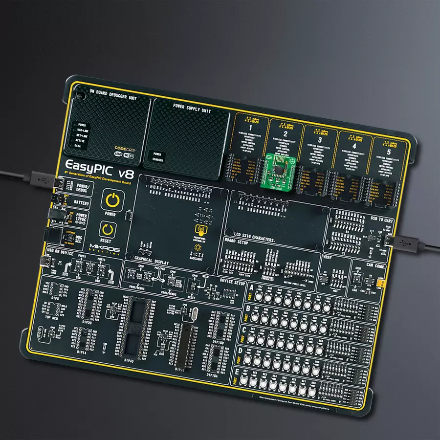
开发板
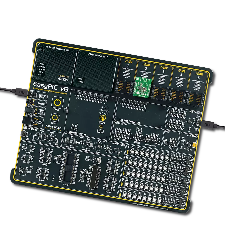
EasyPIC v8 是一款专为快速开发嵌入式应用的需求而特别设计的开发板。它支持许多高引脚计数的8位PIC微控制器,来自Microchip,无论它们的引脚数量如何,并且具有一系列独特功能,例如首次集成的调试器/程序员。开发板布局合理,设计周到,使得最终用户可以在一个地方找到所有必要的元素,如开关、按钮、指示灯、连接器等。得益于创新的制造技术,EasyPIC v8 提供了流畅而沉浸式的工作体验,允许在任何情况下、任何地方、任何时候都能访问。
EasyPIC v8 开发板的每个部分都包含了使同一板块运行最高效的必要组件。除了先进的集成CODEGRIP程 序/调试模块,该模块提供许多有价值的编程/调试选项和与Mikroe软件环境的无缝集成外,该板还包括一个干净且调节过的开发板电源供应模块。它可以使用广泛的外部电源,包括电池、外部12V电源供应和通过USB Type-C(USB-C)连接器的电源。通信选项如USB-UART、USB DEVICE和CAN也包括在内,包括 广受好评的mikroBUS™标准、两种显示选项(图形和
基于字符的LCD)和几种不同的DIP插座。这些插座覆盖了从最小的只有八个至四十个引脚的8位PIC MCU的广泛范围。EasyPIC v8 是Mikroe快速开发生态系统的一个组成部分。它由Mikroe软件工具原生支持,得益于大量不同的Click板™(超过一千块板),其数量每天都在增长,它涵盖了原型制作和开发的许多方面。

微控制器概述
MCU卡片 / MCU
建筑
PIC
MCU 内存 (KB)
32
硅供应商
Microchip
引脚数
28
RAM (字节)
2048
使用的MCU引脚
mikroBUS™映射器
“仔细看看!”
Click board™ 原理图
一步一步来
项目组装

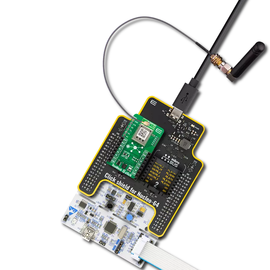
从选择您的开发板和Click板™开始。以EasyPIC v8作为您的开发板开始。


软件支持
库描述
该库包含 ISM Click 驱动程序的 API。
关键功能:
ism_cfg_setup- 配置对象初始化函数。ism_init- 初始化函数。ism_default_cfg- Click 默认配置函数。
开源
代码示例
完整的应用程序代码和一个现成的项目可以通过NECTO Studio包管理器直接安装到NECTO Studio。 应用程序代码也可以在MIKROE的GitHub账户中找到。
/*!
 * @file main.c
 * @brief Ism Click example
 *
 * # Description
 * This library contains API for the ISM Click driver.
 * This example transmits/receives and processes data from ISM Clicks.
 *
 * The demo application is composed of two sections :
 *
 * ## Application Init
 * Initializes driver and performs the default configuration.
 *
 * ## Application Task
 * Transmitter/Receiver task depends on uncommented code.
 * Receiver logging each received byte to the UART for data logging,
 * while transmitter send messages every 1 second.
 *
 * @author Nenad Filipovic
 *
 */

#include "board.h"
#include "log.h"
#include "ism.h"

// Comment out the line below in order to switch the application mode to receiver
#define DEMO_APP_TRANSMITTER

static ism_t ism;
static log_t logger;

static uint8_t demo_message_1[ 9 ] = { 'M', 'i', 'k', 'r', 'o', 'E', 13, 10, 0 };
static uint8_t demo_message_2[ 12 ] = { 'I', 'S', 'M', ' ', 'C', 'l', 'i', 'c', 'k', 13, 10, 0 };

void application_init ( void )
{
    log_cfg_t log_cfg;  /**< Logger config object. */
    ism_cfg_t ism_cfg;  /**< Click config object. */

    /**
     * Logger initialization.
     * Default baud rate: 115200
     * Default log level: LOG_LEVEL_DEBUG
     * @note If USB_UART_RX and USB_UART_TX
     * are defined as HAL_PIN_NC, you will
     * need to define them manually for log to work.
     * See @b LOG_MAP_USB_UART macro definition for detailed explanation.
     */
    LOG_MAP_USB_UART( log_cfg );
    log_init( &logger, &log_cfg );
    log_info( &logger, " Application Init " );

    // Click initialization.
    ism_cfg_setup( &ism_cfg );
    ISM_MAP_MIKROBUS( ism_cfg, MIKROBUS_1 );
    if ( SPI_MASTER_ERROR == ism_init( &ism, &ism_cfg ) )
    {
        log_error( &logger, " Application Init Error. " );
        log_info( &logger, " Please, run program again... " );
        for ( ; ; );
    }

    ism_default_cfg ( &ism );
    Delay_ms ( 100 );

#ifdef DEMO_APP_TRANSMITTER
    ism_switch_tx_mode( &ism );
    log_printf( &logger, " Application Mode: Transmitter\r\n" );
#else
    ism_switch_rx_mode( &ism );
    log_printf( &logger, " Application Mode: Receiver\r\n" );
#endif
    log_info( &logger, " Application Task " );
}

void application_task ( void )
{
#ifdef DEMO_APP_TRANSMITTER
    ism_transmit_packet( &ism, ISM_CMD_W_TX_PAYLOAD_NOACK, demo_message_1, 9 );
    log_printf( &logger, "  Tx : %s", demo_message_1 );
    Delay_ms ( 1000 );

    ism_transmit_packet( &ism, ISM_CMD_W_TX_PAYLOAD_NOACK, demo_message_2, 12 );
    log_printf( &logger, "  Tx : %s", demo_message_2 );
    Delay_ms ( 1000 );
#else
    uint8_t rx_buf[ ISM_MAX_PACKET_LEN ] = { 0 };

    ism_receive_packet( &ism, &rx_buf[ 0 ] );

    if ( rx_buf[ 0 ] )
    {
        log_printf( &logger, "  Rx : %s", rx_buf );
    }
#endif
}

int main ( void )
{
    /* Do not remove this line or clock might not be set correctly. */
    #ifdef PREINIT_SUPPORTED
    preinit();
    #endif

    application_init( );

    for ( ; ; )
    {
        application_task( );
    }

    return 0;
}

// ------------------------------------------------------------------------ END