使用TPS25750S和PIC18F57Q43确保更快、更安全、更多功能的设备充电
插入、播放并充电!

已发布 6月 27, 2024
点击板
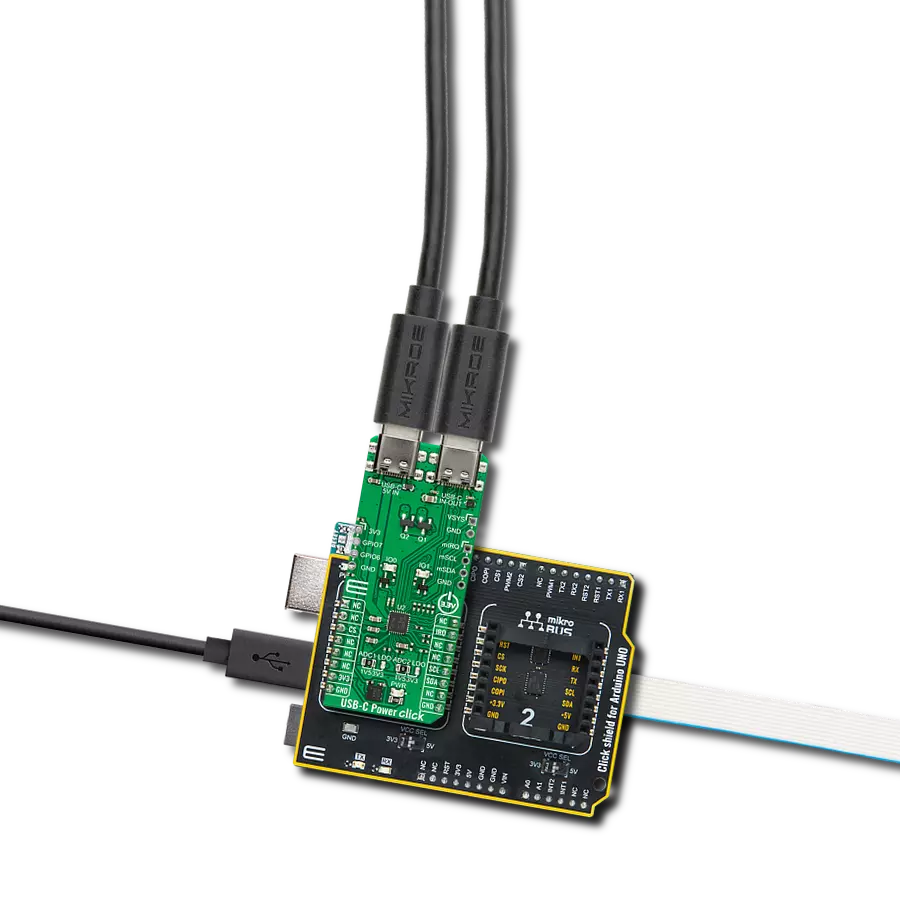
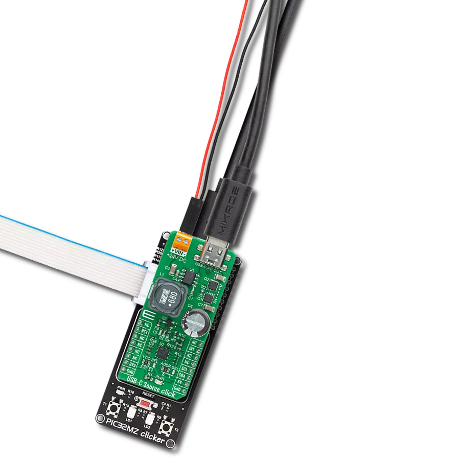
USB-C Power Click
开发板
Curiosity Nano with PIC18F57Q43
编译器
NECTO Studio
微控制器单元
PIC18F57Q43
我们的USB Type-C PD控制器释放了USB Type-C的全部潜力,让您前所未有地充电、传输数据并连接到各种外设。
A
A
硬件概览
它是如何工作的?
USB-C Power Click基于TPS25750S,这是一款来自德州仪器的USB Type-C和电源传输(PD)控制器,提供单个USB Type-C连接器的电缆插入和方向检测。TPS25750S在检测到电缆时通过CC线使用USB PD协议进行通信。当电缆检测和USB PD协商完成后,TPS25750S根据设定的配置启用适当的电源路径,以在USB IN-OUT连接器上提供或接收电源。TPS25750S针对支持USB-C PD电源的应用进行了高度优化,提供了强大的保护和完全管理的内部电源路径(5V/3A,36mΩ源开关)。第二个USB连接器标记为5V IN,用于以USB连接形式提供5V电压,这是内部5V源电源路径所必需的。此Click板™通过标准I2C 2线接口与MCU通信,以读取数据和配置设置,最大频率为
400kHz。此外,它还具有一个额外的中断信号,连接到mikroBUS™插座的IRQ引脚。除了用于与主机MCU通信的I2C端口外,TPS25750S还具有一个最大频率为400kHz的主配置I2C接口,可以连接到电池充电器(如BQ25792)或外部EEPROM,以传达适当的配置以设置充电模式、充电电流、OTG模式等。BQ25792是一款适用于1-4节锂离子和锂聚合物电池的全集成开关模式升降压充电器,允许用户以高达3A的功率源或接收电源。与电池充电器通信所需的电源和线路位于板右侧的未填充引脚上。得益于板载ADC跳线,TPS25750S可以根据位置设置死电池配置和PD控制器的I2C从设备地址。提供的两种死电池配置是安全模式和始终启用接收模式。安全模式不启用接收路径,并且在加载
配置之前禁用USB PD。在始终启用接收模式下,无论连接的源提供的电流量如何,设备都会启用接收路径。在加载配置之前,USB PD被禁用。此Click板™还具有两个位于未填充引脚上的GPIO信号,用于状态和控制信息的用户定义。GPIO引脚可以映射到USB Type-C、USB PD和特定应用事件,以控制其他IC、中断主处理器或接收来自其他IC的输入。除了GPIO,它还具有两个LED指示灯,IO0和IO1,用于在操作期间实现一些异常或状态的视觉检测。此Click板™只能在3.3V逻辑电压水平下运行。使用不同逻辑电平的MCU之前,必须进行适当的逻辑电压电平转换。此外,该Click板™配备了包含功能和示例代码的库,可用作进一步开发的参考。

功能概述
开发板
PIC18F57Q43 Curiosity Nano 评估套件是一款尖端的硬件平台,旨在评估 PIC18-Q43 系列内的微控制器。其设计的核心是包含了功能强大的 PIC18F57Q43 微控制器(MCU),提供先进的功能和稳健的性能。这个评估套件的关键特点包括一个黄 色用户 LED 和一个响应灵敏的机械用户开关,提供无
缝的交互和测试。为一个 32.768kHz 水晶振荡器足迹提供支持,确保精准的定时能力。套件内置的调试器拥有一个绿色电源和状态 LED,使编程和调试变得直观高效。此外,增强其实用性的还有虚拟串行端口 (CDC)和一个调试 GPIO 通道(DGI GPIO),提供广泛的连接选项。该套件通过 USB 供电,拥有由
MIC5353 LDO 调节器提供支持的可调目标电压功能,确保在 1.8V 至 5.1V 的输出电压范围内稳定运行,最大输出电流为 500mA,受环境温度和电压限制。

微控制器概述
MCU卡片 / MCU

建筑
PIC
MCU 内存 (KB)
128
硅供应商
Microchip
引脚数
48
RAM (字节)
8196
你完善了我!
配件
Curiosity Nano Base for Click boards 是一款多功能硬件扩展平台,专为简化 Curiosity Nano 套件与扩展板之间的集成而设计,特别针对符合 mikroBUS™ 标准的 Click 板和 Xplained Pro 扩展板。这款创新的基板(屏蔽板)提供了无缝的连接和扩展可能性,简化了实验和开发过程。主要特点包括从 Curiosity Nano 套件提供 USB 电源兼容性,以及为增强灵活性而提供的另一种外部电源输入选项。板载锂离子/锂聚合物充电器和管理电路确保电池供电应用的平稳运行,简化了使用和管理。此外,基板内置了一个固定的 3.3V 电源供应单元,专用于目标和 mikroBUS™ 电源轨,以及一个固定的 5.0V 升压转换器,专供 mikroBUS™ 插座的 5V 电源轨,为各种连接设备提供稳定的电力供应。

使用的MCU引脚
mikroBUS™映射器
“仔细看看!”
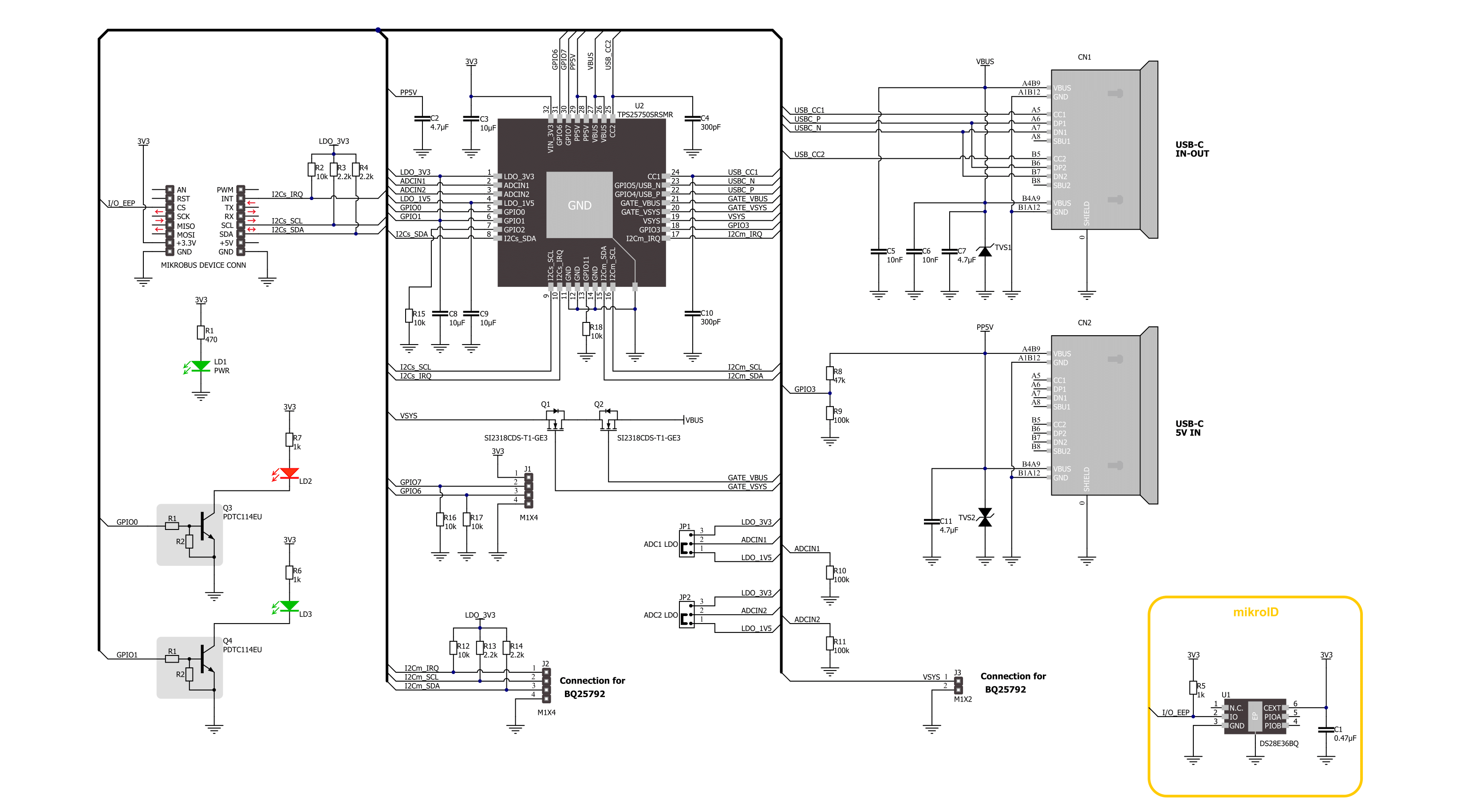
Click board™ 原理图
一步一步来
项目组装

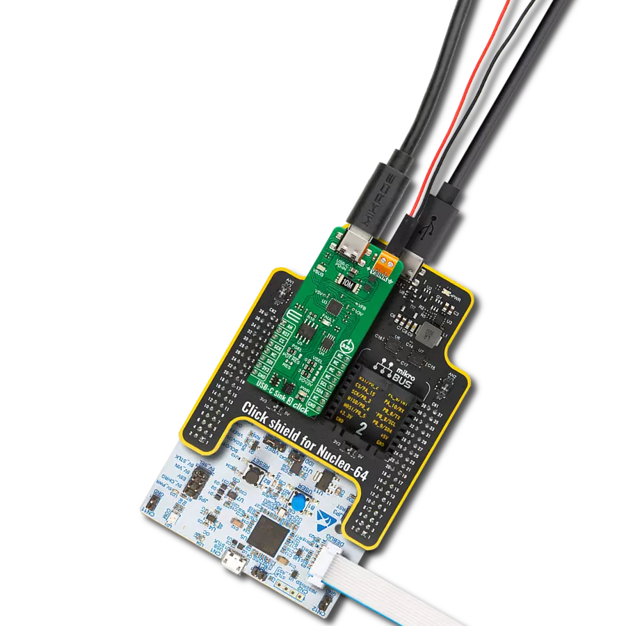
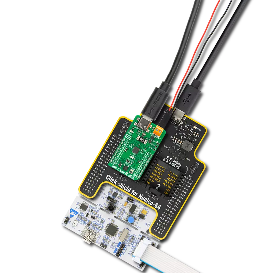
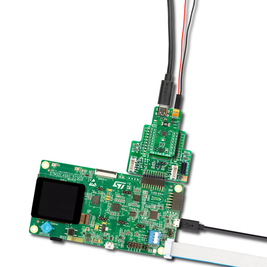
从选择您的开发板和Click板™开始。以Curiosity Nano with PIC18F57Q43作为您的开发板开始。


软件支持
库描述
该库包含 USB-C Power Click 驱动程序的 API。
关键功能:
usbcpower_get_status- USB-C Power获取状态功能。usbcpower_get_pwr_status- USB-C Power获取电源状态功能。usbcpower_start_patch_burst_mode- USB-C Power启动补丁突发模式功能。
开源
代码示例
完整的应用程序代码和一个现成的项目可以通过NECTO Studio包管理器直接安装到NECTO Studio。 应用程序代码也可以在MIKROE的GitHub账户中找到。
/*!
 * @file main.c
 * @brief USB-C Power Click example
 *
 * # Description
 * This example demonstrates the use of the USB-C Power Click board™
 * by configuring the PD controller to attempt to become a Power Source.
 *
 * The demo application is composed of two sections :
 *
 * ## Application Init
 * The initialization of I2C module, log UART, and additional pins.
 * After the driver init, the app executes a default configuration,
 * depending on PD Device Mode, the app performs the patch bundle update tasks
 * for loading a patch bundle in burst mode to the PD controller.
 *
 * ## Application Task
 * The application display status information about
 * the PD controller data role and power of the connection.
 * Results are being sent to the UART Terminal, where you can track their changes.
 *
 * ## Additional Function
 * - static void usbcpower_display_status ( void )
 * - static void usbcpower_display_pwr_status ( void )
 *
 * @note
 * For the advanced configuration, use the TPS25750 Application Customization Tool:
 * https://dev.ti.com/gallery/search/TPS25750_Application_Customization_Tool
 *
 * @author Nenad Filipovic
 *
 */

#include "board.h"
#include "log.h"
#include "usbcpower.h"

static usbcpower_t usbcpower;
static log_t logger;
static uint32_t response;
static usbcpower_status_t status;
static usbcpower_pwr_status_t pwr_status;

/**
 * @brief USB-C Power display status function.
 * @details This function display status information.
 * @return Nothing.
 * @note None.
 */
static void usbcpower_display_status ( void );

/**
 * @brief USB-C Power display PWR status function.
 * @details This function display power of the connection status information.
 * @return Nothing.
 * @note None.
 */
static void usbcpower_display_pwr_status ( void );

void application_init ( void )
{
    log_cfg_t log_cfg;  /**< Logger config object. */
    usbcpower_cfg_t usbcpower_cfg;  /**< Click config object. */

    /**
     * Logger initialization.
     * Default baud rate: 115200
     * Default log level: LOG_LEVEL_DEBUG
     * @note If USB_UART_RX and USB_UART_TX
     * are defined as HAL_PIN_NC, you will
     * need to define them manually for log to work.
     * See @b LOG_MAP_USB_UART macro definition for detailed explanation.
     */
    LOG_MAP_USB_UART( log_cfg );
    log_init( &logger, &log_cfg );
    log_info( &logger, " Application Init " );

    // Click initialization.
    usbcpower_cfg_setup( &usbcpower_cfg );
    USBCPOWER_MAP_MIKROBUS( usbcpower_cfg, MIKROBUS_1 );
    if ( I2C_MASTER_ERROR == usbcpower_init( &usbcpower, &usbcpower_cfg ) )
    {
        log_error( &logger, " Communication init." );
        for ( ; ; );
    }

    if ( USBCPOWER_ERROR == usbcpower_default_cfg ( &usbcpower ) )
    {
        log_error( &logger, " Default configuration." );
        for ( ; ; );
    }

    usbcpower_set_patch_mode( &usbcpower, &response );
    if ( USBCPOWER_RSP_OK != response )
    {
        log_error( &logger, " Go to Patch Mode." );
        for ( ; ; );
    }

    uint8_t device_mode[ 6 ] = { 0 };
    usbcpower_get_device_mode( &usbcpower, &device_mode );
    log_printf( &logger, " PD Device Mode: %s\r\n", &device_mode[ 1 ] );
    log_printf( &logger, "-----------------------------\r\n" );
    Delay_ms ( 100 );

    log_info( &logger, " Application Task " );
    log_printf( &logger, "-----------------------------\r\n" );
    Delay_ms ( 100 );
}

void application_task ( void )
{
    if ( USBCPOWER_OK == usbcpower_get_status( &usbcpower, &status ) )
    {
        if ( USBCPOWER_OK == usbcpower_get_pwr_status( &usbcpower, &pwr_status ) )
        {
            usbcpower_display_status( );
            log_printf( &logger, "- - - - - - - - - - - - - - -\r\n" );
            usbcpower_display_pwr_status( );
            log_printf( &logger, "-----------------------------\r\n" );
        }
    }
    Delay_ms ( 1000 );
    Delay_ms ( 1000 );
    Delay_ms ( 1000 );
}

int main ( void )
{
    /* Do not remove this line or clock might not be set correctly. */
    #ifdef PREINIT_SUPPORTED
    preinit();
    #endif

    application_init( );

    for ( ; ; )
    {
        application_task( );
    }

    return 0;
}

static void usbcpower_display_status ( void )
{
    if ( status.plug_present )
    {
        log_printf( &logger, " A plug is connected.\r\n" );
    }
    else
    {
        log_printf( &logger, " No plug is connected\r\n" );
    }

    if ( USBCPOWER_STATUS_NO_CONNECTION == status.conn_state )
    {
        log_printf( &logger, " No connection.\r\n" );
    }
    else if ( USBCPOWER_STATUS_PORT_DISABLED == status.conn_state )
    {
        log_printf( &logger, " Port is disabled.\r\n" );
    }
    else if ( USBCPOWER_STATUS_AUDIO_CONNECTION == status.conn_state )
    {
        log_printf( &logger, " Audio connection (Ra/Ra).\r\n" );
    }
    else if ( USBCPOWER_STATUS_DEBUG_CONNECTION == status.conn_state )
    {
        log_printf( &logger, " Debug connection (Rd/Rd).\r\n" );
    }
    else if ( USBCPOWER_STATUS_NO_CONNECTION_Ra == status.conn_state )
    {
        log_printf( &logger, " No connection, Ra detected (Ra but no Rd).\r\n" );
    }
    else if ( USBCPOWER_STATUS_RESERVED == status.conn_state )
    {
        log_printf( &logger, " Reserved (may be used for Rp/Rp Debug connection).\r\n" );
    }
    else if ( USBCPOWER_STATUS_CONNECT_NO_Ra == status.conn_state )
    {
        log_printf( &logger, " Connection present, no Ra detected.\r\n" );
    }
    else
    {
        log_printf( &logger, " Connection present, Ra detected.\r\n" );
    }

    if ( status.plug_orientation )
    {
        log_printf( &logger, " Upside-down orientation.\r\n" );
    }
    else
    {
        log_printf( &logger, " Upside-up orientation.\r\n" );
    }

    if ( status.port_role )
    {
        log_printf( &logger, " PD Controller is Source.\r\n" );
    }
    else
    {
        log_printf( &logger, " PD Controller is in the Sink role.\r\n" );
    }
}

static void usbcpower_display_pwr_status ( void )
{
    if ( pwr_status.pwr_conn )
    {
        log_printf( &logger, " Connection present.\r\n" );
    }
    else
    {
        log_printf( &logger, " No connection.\r\n" );
    }

    if ( USBCPOWER_PWR_STATUS_USB == pwr_status.type_c_current )
    {
        log_printf( &logger, " USB Default Current.\r\n" );
    }
    else if ( USBCPOWER_PWR_STATUS_TYPE_C_1_5A  == pwr_status.type_c_current )
    {
        log_printf( &logger, " Type-C Current: 1.5 A\r\n" );
    }
    else if ( USBCPOWER_PWR_STATUS_TYPE_C_3_0A  == pwr_status.type_c_current )
    {
        log_printf( &logger, " Type-C Current: 3.0 A\r\n" );
    }
    else
    {
        log_printf( &logger, "Explicit PD contract sets current.\r\n" );
    }

    if ( USBCPOWER_PWR_STATUS_CHG_ADV_DISABLE == pwr_status.charger_advertise )
    {
        log_printf( &logger, " Charger advertise disabled or not run.\r\n" );
    }
    else if ( USBCPOWER_PWR_STATUS_CHG_ADV_PROCESS == pwr_status.charger_advertise )
    {
        log_printf( &logger, " Charger advertisement in process.\r\n" );
    }
    else if ( USBCPOWER_PWR_STATUS_CHG_ADV_COMPLETE == pwr_status.charger_advertise )
    {
        log_printf( &logger, "Charger advertisement complete.\r\n" );
    }
    else
    {
        log_printf( &logger, "Reserved.\r\n" );
    }
}

// ------------------------------------------------------------------------ END
额外支持
资源
类别:USB-C 电力传输