通过L9637和ATmega328释放ISO 9141的潜力
具有ISO 9141接口的单片总线驱动器

已发布 6月 25, 2024
点击板
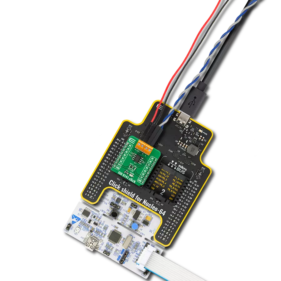
ISO 9141 Click
开发板
Arduino UNO Rev3
编译器
NECTO Studio
微控制器单元
ATmega328
利用符合 ISO9141 标准的双向串行通信功能,实现汽车系统中的有效诊断。
A
A
硬件概览
它是如何工作的?
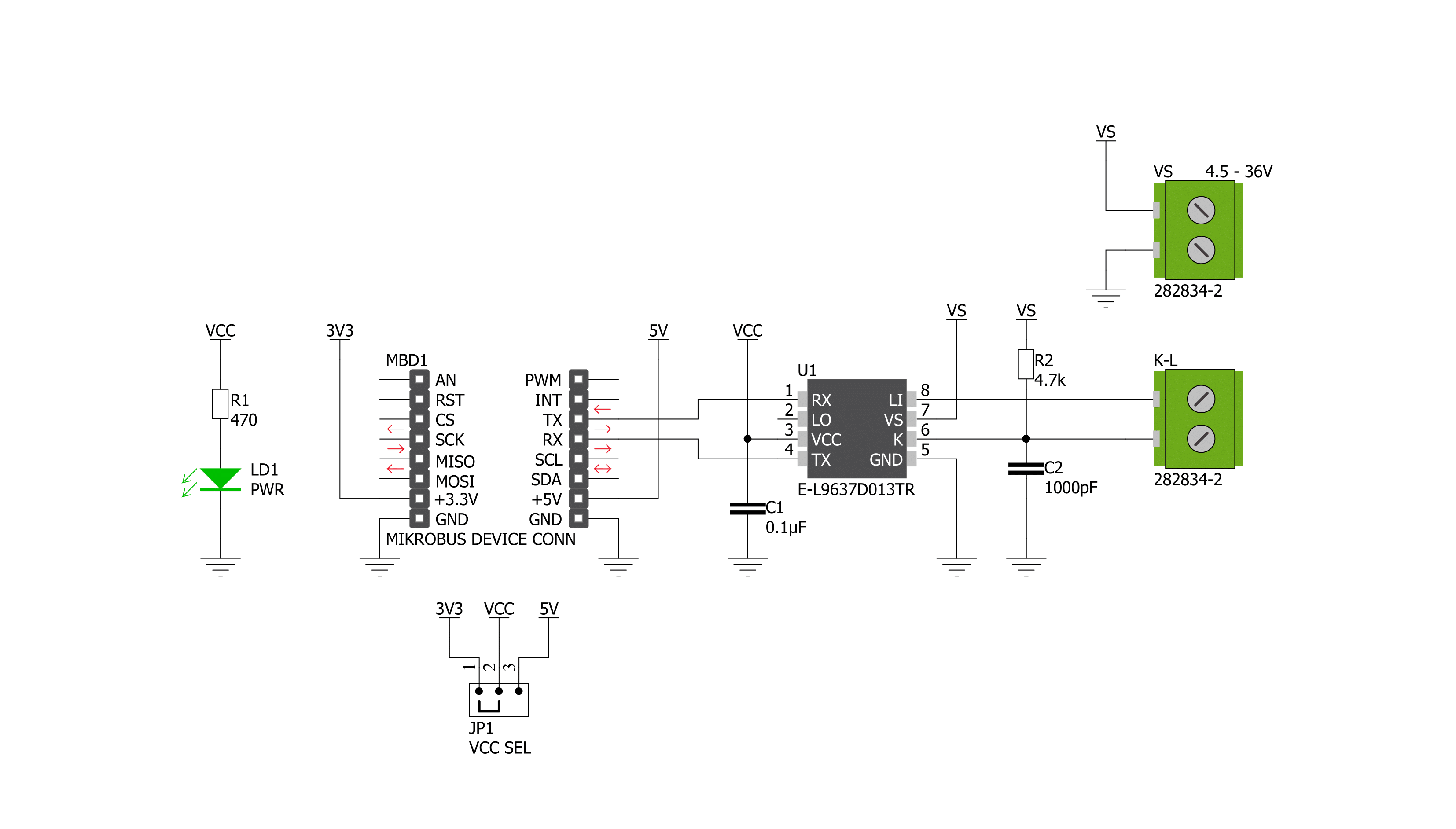
ISO 9141 Click 基于 L9637,这是一款单片总线驱动器,旨在根据 ST Microelectronics 的“诊断系统 ISO9141”规范,在汽车诊断应用中提供双向串行通信。L9637 也被称为 K-Line 收发器,它提供一个称为 K 的双向链接,以及一个称为 L 的单独比较器,与相关诊断总线相连,可以连接到该 Click board™ 上标记为 K 和 L 的端子。K 和 L 引脚具有过电压和反接电池保护功能。在缺乏电源或接地时,所有引脚均表现出高阻抗特性。L9637 具有宽范围的电源电压范围,从 4.5V 到 36V,并具有多种操作模式,如低电流消耗的待机模式和过温关断模式。当 L9637 的温度升高超过热关断阈值
时,过温关断模式将关闭 K 输出。要重新激活 K,温度必须下降到 K 开关开启温度值以下。在电源欠压条件下,输出将关闭并保持高阻抗,以实现无故障。ISO 9141 Click 使用 UART 接口与 MCU 通信,默认波特率为 9600bps,并使用常用的 UART RX 和 TX 引脚进行数据传输。K 的 UART 输入 TX 和输出 RX 与 mikroBUS™(VCC)上的逻辑电压电平相关联,并具有集成的上拉电阻。此外,L 比较器输出引脚 LO 也具有连接到 VCC 的上拉电阻。所有总线定义的输入 L 和 K 具有与电源电压相关的阈值,并具有足够的滞后以抑制线路尖峰。这个 Click board™ 易于编程,因为
它不需要过于复杂的配置。仅需要选择适当的操作模式,无论 Click board™ 将作为接收器还是发射器工作。这样,发射器将每 2 秒发送一次数据,而接收端将以“逐字节”格式接收数据。这也可以在示例代码中看到,示例代码包含易于使用的函数,可以作为进一步开发的参考。这个 Click board™ 设计为可以使用 3.3V 和 5V 逻辑电压水平,通过 VCC SEL 跳线选择。这允许具有 3.3V 和 5V 的 MCU 正确使用 UART 通信线路。此外,这个 Click board™ 配备了一个包含易于使用的函数和示例代码的库,可以作为进一步开发的参考。

功能概述
开发板
Arduino UNO 是围绕 ATmega328P 芯片构建的多功能微控制器板。它为各种项目提供了广泛的连接选项,具有 14 个数字输入/输出引脚,其中六个支持 PWM 输出,以及六个模拟输入。其核心组件包括一个 16MHz 的陶瓷谐振器、一个 USB 连接器、一个电
源插孔、一个 ICSP 头和一个复位按钮,提供了为板 子供电和编程所需的一切。UNO 可以通过 USB 连接到计算机,也可以通过 AC-to-DC 适配器或电池供电。作为第一个 USB Arduino 板,它成为 Arduino 平台的基准,"Uno" 符号化其作为系列首款产品的地
位。这个名称选择,意为意大利语中的 "一",是为了 纪念 Arduino Software(IDE)1.0 的推出。最初与 Arduino Software(IDE)版本1.0 同时推出,Uno 自此成为后续 Arduino 发布的基础模型,体现了该平台的演进。

微控制器概述
MCU卡片 / MCU

建筑
AVR
MCU 内存 (KB)
32
硅供应商
Microchip
引脚数
32
RAM (字节)
2048
你完善了我!
配件
Click Shield for Arduino UNO 具有两个专有的 mikroBUS™ 插座,使所有 Click board™ 设备能够轻松与 Arduino UNO 板进行接口连接。Arduino UNO 是一款基于 ATmega328P 的微控制器开发板,为用户提供了一种经济实惠且灵活的方式来测试新概念并构建基于 ATmega328P 微控制器的原型系统,结合了性能、功耗和功能的多种配置选择。Arduino UNO 具有 14 个数字输入/输出引脚(其中 6 个可用作 PWM 输出)、6 个模拟输入、16 MHz 陶瓷谐振器(CSTCE16M0V53-R0)、USB 接口、电源插座、ICSP 头和复位按钮。大多数 ATmega328P 微控制器的引脚都连接到开发板左右两侧的 IO 引脚,然后再连接到两个 mikroBUS™ 插座。这款 Click Shield 还配备了多个开关,可执行各种功能,例如选择 mikroBUS™ 插座上模拟信号的逻辑电平,以及选择 mikroBUS™ 插座本身的逻辑电压电平。此外,用户还可以通过现有的双向电平转换电压转换器使用任何 Click board™,无论 Click board™ 运行在 3.3V 还是 5V 逻辑电压电平。一旦将 Arduino UNO 板与 Click Shield for Arduino UNO 连接,用户即可访问数百种 Click board™,并兼容 3.3V 或 5V 逻辑电压电平的设备。

使用的MCU引脚
mikroBUS™映射器
“仔细看看!”
Click board™ 原理图
一步一步来
项目组装

从选择您的开发板和Click板™开始。以Arduino UNO Rev3作为您的开发板开始。


实时跟踪您的结果
应用程序输出
1. 应用程序输出 - 在调试模式下,“应用程序输出”窗口支持实时数据监控,直接提供执行结果的可视化。请按照提供的教程正确配置环境,以确保数据正确显示。

2. UART 终端 - 使用UART Terminal通过USB to UART converter监视数据传输,实现Click board™与开发系统之间的直接通信。请根据项目需求配置波特率和其他串行设置,以确保正常运行。有关分步设置说明,请参考提供的教程。

3. Plot 输出 - Plot功能提供了一种强大的方式来可视化实时传感器数据,使趋势分析、调试和多个数据点的对比变得更加直观。要正确设置,请按照提供的教程,其中包含使用Plot功能显示Click board™读数的分步示例。在代码中使用Plot功能时,请使用以下函数:plot(insert_graph_name, variable_name);。这是一个通用格式,用户需要将“insert_graph_name”替换为实际图表名称,并将“variable_name”替换为要显示的参数。

软件支持
库描述
该库包含 ISO 9141 Click 驱动程序的 API。
关键功能:
iso9141_generic_write- 该函数使用 UART 串行接口写入指定数量的数据字节iso9141_generic_read- 该函数使用 UART 串行接口读取指定数量的数据字节iso9141_send_data- 该函数发送数据
开源
代码示例
完整的应用程序代码和一个现成的项目可以通过NECTO Studio包管理器直接安装到NECTO Studio。 应用程序代码也可以在MIKROE的GitHub账户中找到。
/*!
 * @file main.c
 * @brief ISO 9141 Click Example.
 *
 * # Description
 * This example demonstrates the use of an ISO 9141 click board by showing
 * the communication between the two click boards.
 *
 * The demo application is composed of two sections :
 *
 * ## Application Init
 * Initalizes device and makes an initial log.
 *
 * ## Application Task
 * Depending on the selected application mode, it reads all the received data or
 * sends the desired text message once per second.
 *
 * @author MikroE Team
 *
 */

#include "board.h"
#include "log.h"
#include "iso9141.h"

// Comment out the line below in order to switch the application mode to receiver
#define DEMO_APP_TRANSMITTER

// Text message to send in the transmitter application mode
#define DEMO_TEXT_MESSAGE           "MIKROE - ISO 9141 click board\r\n\0"

static iso9141_t iso9141;
static log_t logger;

void application_init ( void )
{
    iso9141_cfg_t iso9141_cfg;
    log_cfg_t logger_cfg;

    /**
     * Logger initialization.
     * Default baud rate: 115200
     * Default log level: LOG_LEVEL_DEBUG
     * @note If USB_UART_RX and USB_UART_TX
     * are defined as HAL_PIN_NC, you will
     * need to define them manually for log to work.
     * See @b LOG_MAP_USB_UART macro definition for detailed explanation.
     */
    LOG_MAP_USB_UART( logger_cfg );
    log_init( &logger, &logger_cfg );
    log_info( &logger, " Application Init " );

    // Click initialization.
    iso9141_cfg_setup( &iso9141_cfg );
    ISO9141_MAP_MIKROBUS( iso9141_cfg, MIKROBUS_1 );
    if ( UART_ERROR == iso9141_init( &iso9141, &iso9141_cfg ) )
    {
        log_error( &logger, " Communication init." );
        for ( ; ; );
    }
#ifdef DEMO_APP_TRANSMITTER
    log_printf( &logger, " Application Mode: Transmitter\r\n" );
#else
    log_printf( &logger, " Application Mode: Receiver\r\n" );
#endif
    log_info( &logger, " Application Task " );
}

void application_task ( void )
{
#ifdef DEMO_APP_TRANSMITTER
    iso9141_generic_write( &iso9141, DEMO_TEXT_MESSAGE, strlen( DEMO_TEXT_MESSAGE ) );
    log_printf( &logger, "%s", ( char * ) DEMO_TEXT_MESSAGE );
    Delay_ms ( 1000 );
#else
    uint8_t rx_byte = 0;
    if ( 1 == iso9141_generic_read( &iso9141, &rx_byte, 1 ) )
    {
       log_printf( &logger, "%c", rx_byte );
    }
#endif
}

int main ( void )
{
    /* Do not remove this line or clock might not be set correctly. */
    #ifdef PREINIT_SUPPORTED
    preinit();
    #endif

    application_init( );

    for ( ; ; )
    {
        application_task( );
    }

    return 0;
}

// ------------------------------------------------------------------------ END
额外支持
资源
类别:控制器局域网络