使用SARA-R510AWS和STM32L073RZ创建与IoT ExpressLink服务的安全连接
为智能设备提供今日与未来的不间断连接

已发布 6月 27, 2024
点击板
IoT ExpressLink 2 Click
开发板
Nucleo-64 with STM32L073RZ MCU
编译器
NECTO Studio
微控制器单元
STM32L073RZ
强大而多功能的物联网开发工具,提供先进功能、安全连接,并通过 5G 准备工作未来保护。
A
A
硬件概览
它是如何工作的?
IoT ExpressLink 2 Click基于u-blox的SARA-R510AWS,这是一款LTE-M AWS IoT ExpressLink模块。内置的AWS IoT ExpressLink认证软件提供了一套新的定制AT命令集,可以直接访问AWS云,极大地加速了上市时间。它具有基于硬件的根信任的直接AWS IoT云访问、安全引导、uFOTA、FOAT、主机OTA、超低功耗睡眠等功能。该模块提供对AWS服务的访问,无需用户在主机MCU上集成任何额外的API。每个步骤都在模块内部处理。该模块支持TCP/IP、MQTT和TLS/DTLS协议。一些u-blox支持的兼容服务是CellLocate和AWS IoT ExpressLink的零触摸配置。通过使用Cat M1半双工,它可以实现375kbit/s
的下行速率和1200 kbit/s的上行速率。该模块具有SMA天线连接器,可连接适当的天线以提高范围和接收信号强度。Click板™背面的Micro SIM卡槽用于安装微型SIM卡。没有有效的SIM卡,设备无法使用,该SIM卡允许连接到蜂窝网络。支持1.8V和3V (U)SIM卡类型。板上的PWR键用于开启设备。有四个测试点用于测试。其中一个是Power On,其余是Sara模块的reset、TXD和RXD。有一个黄色LED表示异步事件标志。该模块支持USB C连接器提供的高速USB 2.0兼容接口。USB接口支持最高480Mbit/s的数据速率。模块本身作为USB设备,可以连接到任何USB主机。USB接口仅用于诊断目的。模块可以通过USB C连接器或
mikroBUS™插座的5V供电。它使用TPS7A7002进行电压调节,这是一款来自德州仪器的非常低输入和辍电3A稳压器。IoT ExpressLink 2 Click使用标准的2线USRT接口与主机MCU进行通信,固定波特率为115200kbps。除了板上的PWR键,您还可以通过PWR引脚为设备供电。WUP引脚配置为低功耗睡眠状态唤醒引脚。RST用于重置设备。此外,除了提到的黄色LED,事件标志还可以通过EVT引脚进行监视。此Click板™可以通过VCC SEL跳线选择3.3V或5V逻辑电压电平运行。这样,既支持3.3V又支持5V的MCU可以正确使用通信线路。此外,该Click板™配备有一个包含易于使用的函数和示例代码的库,可用作进一步开发的参考。

功能概述
开发板
Nucleo-64搭载STM32L073RZ MCU提供了一个经济实惠且灵活的平台,供开发人员探索新的想法并原型化其设计。该板利用了STM32微控制器的多功能性,使用户能够为其项目选择性能和功耗之间的最佳平衡。它采用LQFP64封装的STM32微控制器,并包括一些必要的组件,例如用户LED,可以同时作为ARDUINO®信号使用,以及用户和复位按钮,以及用于精准定时操作的32.768kHz晶体振荡器。设计时考虑了扩展性和灵活性,Nucleo-64板具有ARDUINO®
Uno V3扩展连接器和ST morpho扩展引脚标头,为全面项目集成提供了对STM32 I/O的完全访问权限。电源选项具有适应性,支持ST-LINK USB VBUS或外部电源,确保在各种开发环境中的适应性。该板还配备了一个内置的ST-LINK调试器/编程器,具有USB重新枚举功能,简化了编程和调试过程。此外,该板还设计了外部SMPS,以实现有效的Vcore逻辑供电,支持USB设备全速或USB SNK/UFP全速,以及内置的加密功能,增强了项目的功耗效率和安全性。通过专用
连接器提供了额外的连接性,用于外部SMPS实验、ST-LINK的USB连接器和MIPI®调试连接器,扩展了硬件接口和实验的可能性。开发人员将通过STM32Cube MCU软件包中全面的免费软件库和示例得到广泛的支持。这与与各种集成开发环境(IDE)的兼容性相结合,包括IAR Embedded Workbench®、MDK-ARM和STM32CubeIDE,确保了平稳高效的开发体验,使用户能够充分发挥Nucleo-64板在其项目中的功能。

微控制器概述
MCU卡片 / MCU

建筑
ARM Cortex-M0
MCU 内存 (KB)
192
硅供应商
STMicroelectronics
引脚数
64
RAM (字节)
20480
你完善了我!
配件
Click Shield for Nucleo-64 配备了两个专有的 mikroBUS™ 插座,使得所有的 Click board™ 设备都可以轻松地与 STM32 Nucleo-64 开发板连接。这样,Mikroe 允许其用户从不断增长的 Click boards™ 范围中添加任何功能,如 WiFi、GSM、GPS、蓝牙、ZigBee、环境传感器、LED、语音识别、电机控制、运动传感器等。您可以使用超过 1537 个 Click boards™,这些 Click boards™ 可以堆叠和集成。STM32 Nucleo-64 开发板基于 64 引脚封装的微控制器,采用 32 位 MCU,配备 ARM Cortex M4 处理器,运行速度为 84MHz,具有 512Kb Flash 和 96KB SRAM,分为两个区域,顶部区域代表 ST-Link/V2 调试器和编程器,而底部区域是一个实际的开发板。通过 USB 连接方便地控制和供电这些板子,以便直接对 Nucleo-64 开发板进行编程和高效调试,其中还需要额外的 USB 线连接到板子上的 USB 迷你接口。大多数 STM32 微控制器引脚都连接到了板子左右边缘的 IO 引脚上,然后连接到两个现有的 mikroBUS™ 插座上。该 Click Shield 还有几个开关,用于选择 mikroBUS™ 插座上模拟信号的逻辑电平和 mikroBUS™ 插座本身的逻辑电压电平。此外,用户还可以通过现有的双向电平转换器,使用任何 Click board™,无论 Click board™ 是否在 3.3V 或 5V 逻辑电压电平下运行。一旦将 STM32 Nucleo-64 开发板与我们的 Click Shield for Nucleo-64 连接,您就可以访问数百个工作于 3.3V 或 5V 逻辑电压电平的 Click boards™。

这款带有可调角度的多频LTE橡胶天线是我们提供的所有3G/4G LTE Click板的绝佳选择,以及其他需要在全球所有主要蜂窝频段上具有出色吞吐量的设备。该天线具有SMA公头连接器,可直接安装在Click板™或女性SMA模块连接器上。天线位置可在45度增量(0度/45度/90度)中调整。

使用的MCU引脚
mikroBUS™映射器
“仔细看看!”
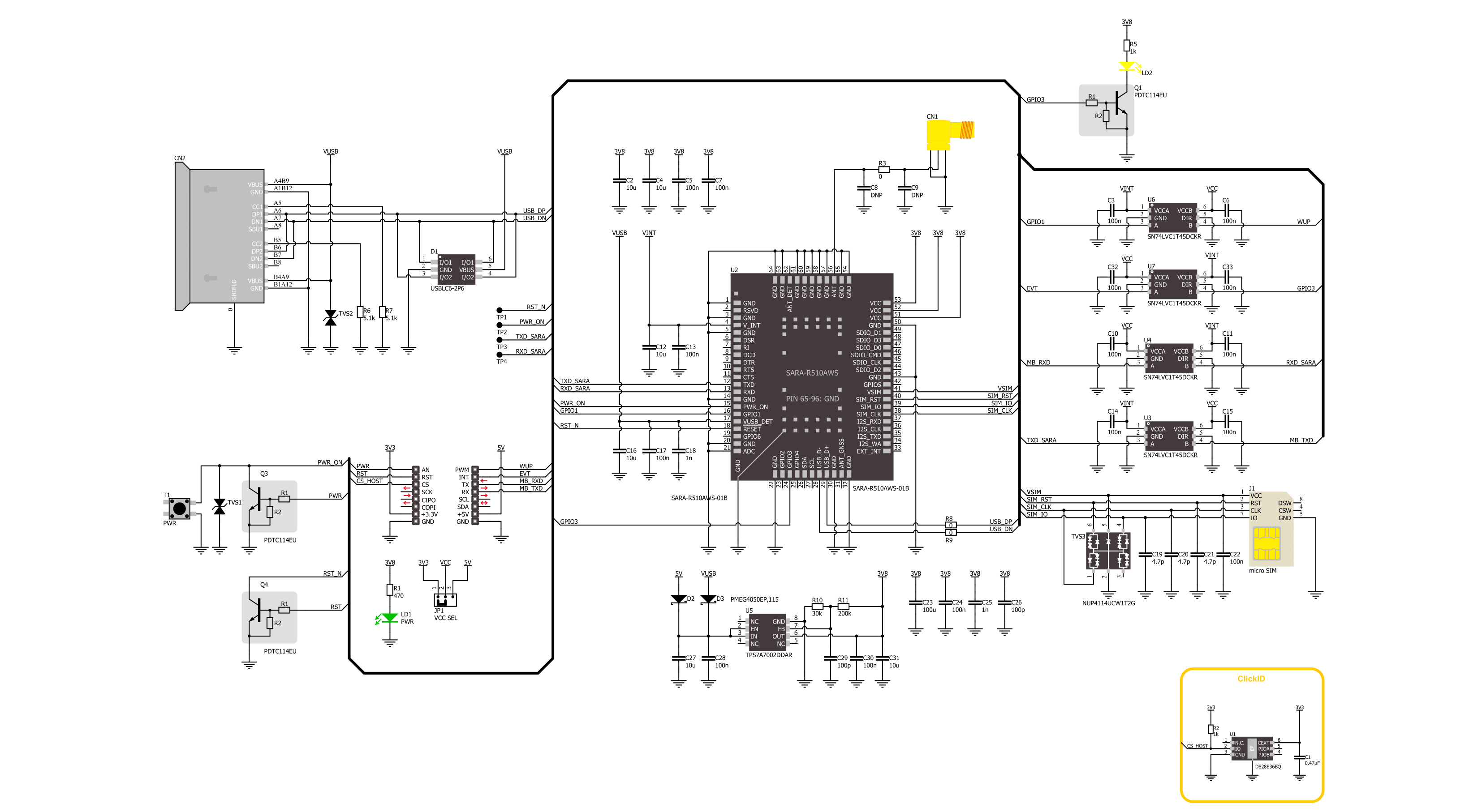
Click board™ 原理图
一步一步来
项目组装
从选择您的开发板和Click板™开始。以Nucleo-64 with STM32L073RZ MCU作为您的开发板开始。


实时跟踪您的结果
应用程序输出
1. 应用程序输出 - 在调试模式下,“应用程序输出”窗口支持实时数据监控,直接提供执行结果的可视化。请按照提供的教程正确配置环境,以确保数据正确显示。

2. UART 终端 - 使用UART Terminal通过USB to UART converter监视数据传输,实现Click board™与开发系统之间的直接通信。请根据项目需求配置波特率和其他串行设置,以确保正常运行。有关分步设置说明,请参考提供的教程。

3. Plot 输出 - Plot功能提供了一种强大的方式来可视化实时传感器数据,使趋势分析、调试和多个数据点的对比变得更加直观。要正确设置,请按照提供的教程,其中包含使用Plot功能显示Click board™读数的分步示例。在代码中使用Plot功能时,请使用以下函数:plot(insert_graph_name, variable_name);。这是一个通用格式,用户需要将“insert_graph_name”替换为实际图表名称,并将“variable_name”替换为要显示的参数。

软件支持
库描述
该库包含 IoT ExpressLink 2 Click 驱动程序的 API。
关键功能:
iotexpresslink2_power_on- 此函数执行开机序列。iotexpresslink2_send_cmd- 此函数通过使用 UART 串行接口发送命令字符串。iotexpresslink2_generic_read- 此函数通过使用 UART 串行接口读取所需数量的数据字节。
开源
代码示例
完整的应用程序代码和一个现成的项目可以通过NECTO Studio包管理器直接安装到NECTO Studio。 应用程序代码也可以在MIKROE的GitHub账户中找到。
/*!
 * @file main.c
 * @brief IoT ExpressLink 2 Click Example.
 *
 * # Description
 * This example demonstrates the use of IoT ExpressLink 2 click board by connecting
 * to the selected AWS account's data endpoint and showcasing the messaging topic model
 * through sending and receiving messages to/from AWS IoT console.
 *
 * The demo application is composed of two sections :
 *
 * ## Application Init
 * Initializes the driver and logger, powers up the device, reads and displays
 * the vendor model, thing name, and the PEM certificate of the device. It then sets
 * the SIM APN and device endpoint, and attempts to connect to AWS network.
 * Finally, it configures the topic name and number and subscribes to it.
 *
 * ## Application Task
 * Sends a desired message on the configured topic and retrieves the next two pending
 * messages from the same topic approximately every 10 seconds. The sent message is also
 * added to the receive queue because the same topic is used for both sending and receiving.
 *
 * ## Additional Function
 * - static void iotexpresslink2_clear_app_buf ( void )
 * - static err_t iotexpresslink2_process ( iotexpresslink2_t *ctx )
 * - static err_t iotexpresslink2_read_response ( iotexpresslink2_t *ctx, uint32_t timeout )
 *
 * @note
 * Steps for the very first connection attempt:
 *  1. During the initial connection attempt, the device responds with: "ERR14 UNABLE TO CONNECT
 * Certificate generation completed. Proceed to register device with AWS cloud and then try
 * to connect again".
 *  2. At this point, you should restart the system and proceed with registering the device
 * with the AWS Cloud using device's thing name and PEM certificate displayed in the logger.
 * Detailed steps for registering device are described in the module's application development guide.
 *  3. After registering the device with your AWS account, restart the system, and it should
 * now successfully connect to the cloud.
 *
 * @author Stefan Filipovic
 *
 */

#include "board.h"
#include "log.h"
#include "iotexpresslink2.h"

// Enter valid APN below for inserted SIM card
#define SIM_APN                 "internet"

// Enter the device data endpoint below for your AWS account in form:
// xxxxxxxxxxxxxx-ats.iot.us-east-1.amazonaws.com
#define DEVICE_ENDPOINT         ""

// Device topic and text message
#define TOPIC_NUM               "1"
#define TOPIC_NAME              "IoT_ExpressLink_2"
#define TEXT_MESSAGE            "IoT ExpressLink 2 click board - demo message"

// Application buffer size
#define APP_BUFFER_SIZE         900
#define PROCESS_BUFFER_SIZE     100

static iotexpresslink2_t iotexpresslink2;
static log_t logger;

static uint8_t app_buf[ APP_BUFFER_SIZE ] = { 0 };
static int32_t app_buf_len = 0;

/**
 * @brief IoT ExpressLink 2 clearing application buffer.
 * @details This function clears memory of application buffer and reset its length.
 * @note None.
 */
static void iotexpresslink2_clear_app_buf ( void );

/**
 * @brief IoT ExpressLink 2 data reading function.
 * @details This function reads data from device and concatenates data to application buffer.
 * @param[in] ctx : Click context object.
 * See #iotexpresslink2_t object definition for detailed explanation.
 * @return @li @c  0 - Read some data.
 *         @li @c -1 - Nothing is read.
 * See #err_t definition for detailed explanation.
 * @note None.
 */
static err_t iotexpresslink2_process ( iotexpresslink2_t *ctx );

/**
 * @brief IoT ExpressLink read response function.
 * @details This function waits for a response message, reads and displays it on the USB UART.
 * @param[in] ctx : Click context object.
 * See #iotexpresslink_t object definition for detailed explanation.
 * @param[in] timeout : Timeout for command response in milliseconds.
 * @return @li @c  0 - OK response.
 *         @li @c -1 - Unknown error.
 *         @li @c -2 - Timeout error.
 *         @li @c -3 - Command error.
 * See #err_t definition for detailed explanation.
 * @note None.
 */
static err_t iotexpresslink2_read_response ( iotexpresslink2_t *ctx, uint32_t timeout );

void application_init ( void )
{
    log_cfg_t log_cfg;  /**< Logger config object. */
    iotexpresslink2_cfg_t iotexpresslink2_cfg;  /**< Click config object. */

    /**
     * Logger initialization.
     * Default baud rate: 115200
     * Default log level: LOG_LEVEL_DEBUG
     * @note If USB_UART_RX and USB_UART_TX
     * are defined as HAL_PIN_NC, you will
     * need to define them manually for log to work.
     * See @b LOG_MAP_USB_UART macro definition for detailed explanation.
     */
    LOG_MAP_USB_UART( log_cfg );
    log_init( &logger, &log_cfg );
    log_info( &logger, " Application Init " );

    // Click initialization.
    iotexpresslink2_cfg_setup( &iotexpresslink2_cfg );
    IOTEXPRESSLINK2_MAP_MIKROBUS( iotexpresslink2_cfg, MIKROBUS_1 );
    if ( UART_ERROR == iotexpresslink2_init( &iotexpresslink2, &iotexpresslink2_cfg ) )
    {
        log_error( &logger, " Communication init." );
        for ( ; ; );
    }
    log_printf( &logger, "Power up device\r\n\n" );
    iotexpresslink2_power_on ( &iotexpresslink2 );

    log_printf( &logger, "Get vendor model\r\n" );
    strcpy ( app_buf, IOTEXPRESSLINK2_CMD_CONF_CHECK );
    strcat ( app_buf, IOTEXPRESSLINK2_CMD_SEPARATOR );
    strcat ( app_buf, IOTEXPRESSLINK2_CONF_KEY_ABOUT );
    iotexpresslink2_send_cmd ( &iotexpresslink2, app_buf );
    iotexpresslink2_read_response ( &iotexpresslink2, IOTEXPRESSLINK2_NORMAL_TIMEOUT );

    log_printf( &logger, "Get thing name\r\n" );
    strcpy ( app_buf, IOTEXPRESSLINK2_CMD_CONF_CHECK );
    strcat ( app_buf, IOTEXPRESSLINK2_CMD_SEPARATOR );
    strcat ( app_buf, IOTEXPRESSLINK2_CONF_KEY_THING_NAME );
    iotexpresslink2_send_cmd ( &iotexpresslink2, app_buf );
    iotexpresslink2_read_response ( &iotexpresslink2, IOTEXPRESSLINK2_NORMAL_TIMEOUT );

    log_printf( &logger, "Get certificate pem\r\n" );
    strcpy ( app_buf, IOTEXPRESSLINK2_CMD_CONF_CHECK );
    strcat ( app_buf, IOTEXPRESSLINK2_CMD_SEPARATOR );
    strcat ( app_buf, IOTEXPRESSLINK2_CONF_KEY_CERTIFICATE_PEM );
    iotexpresslink2_send_cmd ( &iotexpresslink2, app_buf );
    iotexpresslink2_read_response ( &iotexpresslink2, IOTEXPRESSLINK2_NORMAL_TIMEOUT );

    log_printf( &logger, "Set SIM APN to: %s\r\n", ( char * ) SIM_APN );
    strcpy ( app_buf, IOTEXPRESSLINK2_CMD_CONF );
    strcat ( app_buf, IOTEXPRESSLINK2_CMD_SEPARATOR );
    strcat ( app_buf, IOTEXPRESSLINK2_CONF_KEY_APN );
    strcat ( app_buf, IOTEXPRESSLINK2_CMD_SIGN_EQUAL );
    strcat ( app_buf, SIM_APN );
    iotexpresslink2_send_cmd ( &iotexpresslink2, app_buf );
    iotexpresslink2_read_response ( &iotexpresslink2, IOTEXPRESSLINK2_NORMAL_TIMEOUT );

    log_printf( &logger, "Set device endpoint to: %s\r\n", ( char * ) DEVICE_ENDPOINT );
    strcpy ( app_buf, IOTEXPRESSLINK2_CMD_CONF );
    strcat ( app_buf, IOTEXPRESSLINK2_CMD_SEPARATOR );
    strcat ( app_buf, IOTEXPRESSLINK2_CONF_KEY_ENDPOINT );
    strcat ( app_buf, IOTEXPRESSLINK2_CMD_SIGN_EQUAL );
    strcat ( app_buf, DEVICE_ENDPOINT );
    iotexpresslink2_send_cmd ( &iotexpresslink2, app_buf );
    iotexpresslink2_read_response ( &iotexpresslink2, IOTEXPRESSLINK2_NORMAL_TIMEOUT );

    log_printf( &logger, "Trying to connect...\r\n" );
    log_printf( &logger, "This may take up to 15min for the initial connect.\r\n" );
    iotexpresslink2_send_cmd ( &iotexpresslink2, IOTEXPRESSLINK2_CMD_CONNECT );
    if ( IOTEXPRESSLINK2_OK !=
         iotexpresslink2_read_response ( &iotexpresslink2, IOTEXPRESSLINK2_CONNECT_TIMEOUT ) )
    {
        log_printf( &logger, "\r\nUNABLE TO CONNECT\r\n" );
        log_printf( &logger, "Make sure that the SIM card is inserted in the board, \r\n" );
        log_printf( &logger, "an antenna is connected, and the module is within range \r\n" );
        log_printf( &logger, "of a cellular network that provides LTE-M coverage.\r\n" );
        log_printf( &logger, "Double check that the device registration procedure have been \r\n" );
        log_printf( &logger, "correctly followed. If CONNECT worked in the past for this \r\n" );
        log_printf( &logger, "device, it may be that the cellular network has decided \r\n" );
        log_printf( &logger, "to refuse service for a \"guard time\" (e.g. 1 hour) because \r\n" );
        log_printf( &logger, "the device has connected and disconnected more than a handful \r\n" );
        log_printf( &logger, "of times in quick succession. The only way to avoid this is \r\n" );
        log_printf( &logger, "avoiding many connections/disconnections. \r\n" );
        for ( ; ; );
    }

    log_printf( &logger, "Set topic %s to: %s\r\n", ( char * ) TOPIC_NUM, ( char * ) TOPIC_NAME );
    strcpy ( app_buf, IOTEXPRESSLINK2_CMD_CONF );
    strcat ( app_buf, IOTEXPRESSLINK2_CMD_SEPARATOR );
    strcat ( app_buf, IOTEXPRESSLINK2_CONF_KEY_TOPIC );
    strcat ( app_buf, TOPIC_NUM );
    strcat ( app_buf, IOTEXPRESSLINK2_CMD_SIGN_EQUAL );
    strcat ( app_buf, TOPIC_NAME );
    iotexpresslink2_send_cmd ( &iotexpresslink2, app_buf );
    iotexpresslink2_read_response ( &iotexpresslink2, IOTEXPRESSLINK2_NORMAL_TIMEOUT );

    log_printf( &logger, "Subscribe to topic %s\r\n", ( char * ) TOPIC_NUM );
    strcpy ( app_buf, IOTEXPRESSLINK2_CMD_SUBSCRIBE );
    strcat ( app_buf, TOPIC_NUM );
    iotexpresslink2_send_cmd ( &iotexpresslink2, app_buf );
    iotexpresslink2_read_response ( &iotexpresslink2, IOTEXPRESSLINK2_NORMAL_TIMEOUT );

    log_info( &logger, " Application Task " );
}

void application_task ( void )
{
    // Send message on topic
    log_printf( &logger, "Send message on topic: %s\r\n", ( char * ) TOPIC_NAME );
    strcpy ( app_buf, IOTEXPRESSLINK2_CMD_SEND );
    strcat ( app_buf, TOPIC_NUM );
    strcat ( app_buf, IOTEXPRESSLINK2_CMD_SEPARATOR );
    strcat ( app_buf, TEXT_MESSAGE );
    iotexpresslink2_send_cmd ( &iotexpresslink2, app_buf );
    iotexpresslink2_read_response ( &iotexpresslink2, IOTEXPRESSLINK2_NORMAL_TIMEOUT );
    Delay_ms ( 1000 );

    // Retrieve the next message received on topic in the order of arrival.
    log_printf( &logger, "Request next message pending on topic: %s\r\n", ( char * ) TOPIC_NAME );
    strcpy ( app_buf, IOTEXPRESSLINK2_CMD_GET );
    strcat ( app_buf, TOPIC_NUM );
    iotexpresslink2_send_cmd ( &iotexpresslink2, app_buf );
    iotexpresslink2_read_response ( &iotexpresslink2, IOTEXPRESSLINK2_NORMAL_TIMEOUT );
    Delay_ms ( 8000 );
}

int main ( void )
{
    application_init( );

    for ( ; ; )
    {
        application_task( );
    }

    return 0;
}

static void iotexpresslink2_clear_app_buf ( void )
{
    memset( app_buf, 0, APP_BUFFER_SIZE );
    app_buf_len = 0;
}

static void iotexpresslink2_log_app_buf ( void )
{
    for ( int32_t buf_cnt = 0; buf_cnt < app_buf_len; buf_cnt++ )
    {
        log_printf( &logger, "%c", app_buf[ buf_cnt ] );
    }
}

static err_t iotexpresslink2_process ( iotexpresslink2_t *ctx )
{
    uint8_t rx_buf[ PROCESS_BUFFER_SIZE ] = { 0 };
    int32_t overflow_bytes = 0;
    int32_t rx_cnt = 0;
    int32_t rx_size = iotexpresslink2_generic_read( ctx, rx_buf, PROCESS_BUFFER_SIZE );
    if ( ( rx_size > 0 ) && ( rx_size <= APP_BUFFER_SIZE ) )
    {
        if ( ( app_buf_len + rx_size ) > APP_BUFFER_SIZE )
        {
            overflow_bytes = ( app_buf_len + rx_size ) - APP_BUFFER_SIZE;
            app_buf_len = APP_BUFFER_SIZE - rx_size;
            memmove ( app_buf, &app_buf[ overflow_bytes ], app_buf_len );
            memset ( &app_buf[ app_buf_len ], 0, overflow_bytes );
        }
        for ( rx_cnt = 0; rx_cnt < rx_size; rx_cnt++ )
        {
            if ( rx_buf[ rx_cnt ] )
            {
                app_buf[ app_buf_len++ ] = rx_buf[ rx_cnt ];
            }
        }
        return IOTEXPRESSLINK2_OK;
    }
    return IOTEXPRESSLINK2_ERROR;
}

static err_t iotexpresslink2_read_response ( iotexpresslink2_t *ctx, uint32_t timeout )
{
    uint32_t timeout_cnt = 0;
    iotexpresslink2_clear_app_buf ( );
    iotexpresslink2_process( ctx );
    while ( ( 0 == strstr( app_buf, IOTEXPRESSLINK2_RSP_OK ) ) &&
            ( 0 == strstr( app_buf, IOTEXPRESSLINK2_RSP_ERR ) ) )
    {
        iotexpresslink2_process( ctx );
        if ( timeout_cnt++ > timeout )
        {
            iotexpresslink2_clear_app_buf( );
            return IOTEXPRESSLINK2_ERROR_TIMEOUT;
        }
        Delay_ms( 1 );
    }
    Delay_ms ( 100 );
    while ( IOTEXPRESSLINK2_OK == iotexpresslink2_process( ctx ) )
    {
        Delay_ms ( 100 );
    }
    if ( app_buf_len > 0 )
    {
        log_printf( &logger, "%s\r\n", app_buf );
    }
    Delay_ms ( 100 );
    if ( strstr( app_buf, IOTEXPRESSLINK2_RSP_OK ) )
    {
        iotexpresslink2_clear_app_buf( );
        return IOTEXPRESSLINK2_OK;
    }
    else if ( strstr( app_buf, IOTEXPRESSLINK2_RSP_ERR ) )
    {
        iotexpresslink2_clear_app_buf( );
        return IOTEXPRESSLINK2_ERROR_CMD;
    }
    iotexpresslink2_clear_app_buf( );
    return IOTEXPRESSLINK2_ERROR;
}

// ------------------------------------------------------------------------ END


