使用TPS54200和STM32F410RB实现智能照明控制的无缝集成
照明创新触手可及

已发布 10月 08, 2024
点击板
LED Driver 5 Click
开发板
Nucleo 64 with STM32F410RB MCU
编译器
NECTO Studio
微控制器单元
STM32F410RB
凭借我们的精密 LED 驱动技术,确保您的电子产品中 LED 照明的一致性和稳定性。
A
A
硬件概览
它是如何工作的?
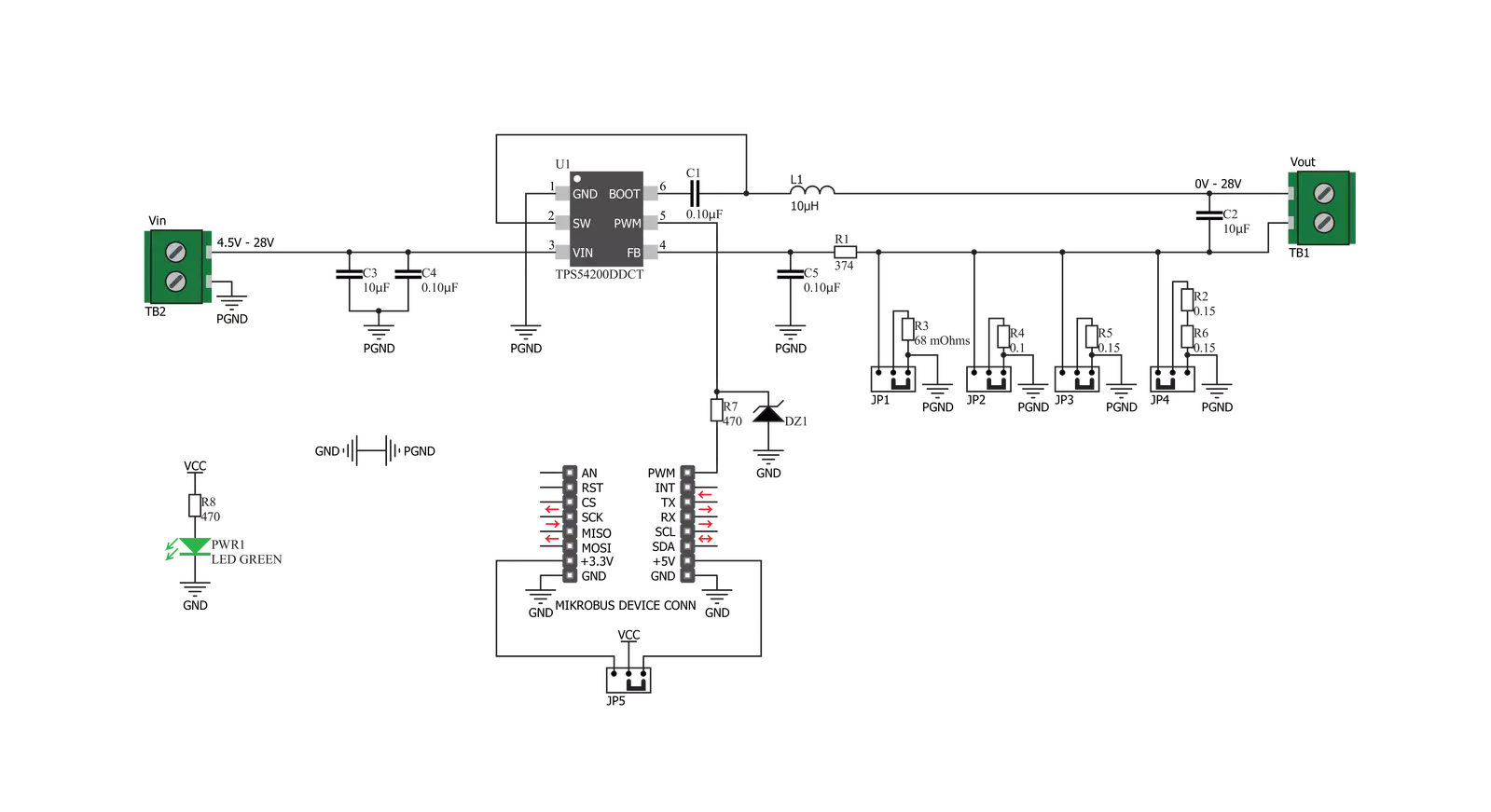
LED Driver 5 Click 基于 TPS54200,这是一款同步降压转换器,专为驱动由 Texas Instruments 制造的单色、彩色和红外 LED 阵列而设计。该 Click 板在输入电压选择方面非常灵活,允许使用 4.5V 至 28V 的任何电压。这得益于 TPS54200 驱动 IC,该 IC 集成了降压转换器 IC,并支持通过控制输入上的 PWM 信号脉宽来调节 LED 的亮度。此 IC 具有模式选择逻辑电路,用于根据输入的 PWM 控制信号电平选择两种调光模式之一。PWM 引脚用于控制多个功能。除了选择调光模式(模拟或 PWM),该引脚还用于开启或关闭 IC。如果 PWM 引脚上的信号上升超过阈值(通常为 0.56V),则 IC 将启用。将 PWM 引脚上的电压保持低于 0.56V 至少 40 毫秒将禁用 IC。启用设备后,内部峰值检测器会检测并存储 PWM 信号的幅度。然后在 300 µs 后,将峰值检测器的电压与两个阈值 VADIM 和 VPDIM 进行比较。如果峰值检测器输出超过 2.07V,将选择并锁定模拟调光模式。如果峰值检测器电压在 1V 到 2.07V
之间,将选择并锁定 PWM 调光模式。如果电压小于 1V,则在 300 µs 后重复检测过程,直到选择并锁定其中一种操作模式。一旦锁定,只有通过循环 VIN 电压或重新启用 IC 才能更改调光模式。PWM 引脚连接到 mikroBUS™ 的 PWM 引脚,可以由主微控制器 (MCU) 控制。当选择模拟调光模式时(在 TPS54200 的启动序列期间控制 PWM 信号的幅度高于 2.06V),内部参考电压 (VREF) 根据应用于 PWM 引脚的 PWM 信号的占空比进行缩放。此模式的内部参考电压在满量程时为 200 mV(占空比为 100%)。随着占空比的减少,参考电压将缩放到其值的 1%。这也将导致 LED 电流缩放,有效地调暗 LED。这种类型的调光,有时称为深度调光,LED 强度调节到肉眼看不见的低水平。PWM 引脚上的 PWM 控制信号应保持在 10 kHz 范围内,以减少输出电压纹波。如果选择 PWM 调光模式(在 TPS54200 的启动序列期间控制 PWM 信号的幅度在 1V 和 2.06V 之间),内部参考电压固定为
100mA。在此模式下,LED 调光通过应用于 PWM 引脚的 PWM 信号进行,调节 LED 输出。保持内部参考电压固定,输出的 LED 仅根据控制 PWM 信号的占空比开关。降压转换器本身是一种功能丰富的电路,同步降压转换器,工作频率固定为 600kHz。这提供了卓越的尺寸/效率比,保持 TPS54200 IC 的占地面积非常小。开放 LED 或短路 LED 检测、过压和欠压保护、过流和开环保护、热关断和软启动功能(防止浪涌电流)等功能使 Click 板成为驱动高电流 LED 或 LED 阵列的非常可靠且安全的解决方案。Click 板包含四个 SMD 跳线,用于选择通过 LED 阵列的电流。它们分组并标记为 IOUT。有四个设置:0.35A、0.7A、1A 和 1.5A。将电流选择 SMD 跳线切换到 ON 位置将连接相应的感应电阻 (RS) 到电路中。同时将两个 SMD 跳线切换到 ON 位置将使它们与其等效电阻形成并联连接。然而,这不推荐,因为几乎所有电阻组合将导致值太低而无法使用(LED 电流将超过 1.5A,从而触发保护电路)。

功能概述
开发板
Nucleo-64 搭载 STM32F410RB MCU 提供了一种经济高效且灵活的平台,供开发者探索新想法并原型设计他们的项目。该板利用 STM32 微控制器的多功能性,使用户能够为他们的项目选择最佳的性能与功耗平衡。它配备了 LQFP64 封装的 STM32 微控制器,并包含了如用户 LED(同时作为 ARDUINO® 信号)、用户和复位按钮,以及 32.768kHz 晶体振荡器用于精确的计时操作等基本组件。Nucleo-64 板设计考虑到扩展性和灵活性,它特有的 ARDUINO® Uno
V3 扩展连接器和 ST morpho 扩展引脚头,提供了对 STM32 I/O 的完全访问,以实现全面的项目整合。电源供应选项灵活,支持 ST-LINK USB VBUS 或外部电源,确保在各种开发环境中的适应性。该板还配备了一个具有 USB 重枚举功能的板载 ST-LINK 调试器/编程器,简化了编程和调试过程。此外,该板设计旨在简化高级开发,它的外部 SMPS 为 Vcore 逻辑供电提供高效支持,支持 USB 设备全速或 USB SNK/UFP 全速,并内置加密功能,提升了项目的功效
和安全性。通过外部 SMPS 实验的专用连接器、 用于 ST-LINK 的 USB 连接器以及 MIPI® 调试连接器,提供了更多的硬件接口和实验可能性。开发者将通过 STM32Cube MCU Package 提供的全面免费软件库和示例得到广泛支持。这些,加上与多种集成开发环境(IDE)的兼容性,包括 IAR Embedded Workbench®、MDK-ARM 和 STM32CubeIDE,确保了流畅且高效的开发体验,使用户能够充分利用 Nucleo-64 板在他们的项目中的能力。

微控制器概述
MCU卡片 / MCU

建筑
ARM Cortex-M4
MCU 内存 (KB)
128
硅供应商
STMicroelectronics
引脚数
64
RAM (字节)
32768
你完善了我!
配件
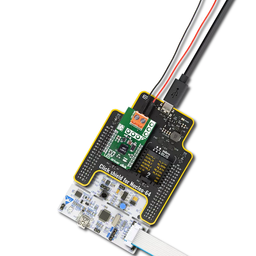
Click Shield for Nucleo-64 配备了两个专有的 mikroBUS™ 插座,使得所有的 Click board™ 设备都可以轻松地与 STM32 Nucleo-64 开发板连接。这样,Mikroe 允许其用户从不断增长的 Click boards™ 范围中添加任何功能,如 WiFi、GSM、GPS、蓝牙、ZigBee、环境传感器、LED、语音识别、电机控制、运动传感器等。您可以使用超过 1537 个 Click boards™,这些 Click boards™ 可以堆叠和集成。STM32 Nucleo-64 开发板基于 64 引脚封装的微控制器,采用 32 位 MCU,配备 ARM Cortex M4 处理器,运行速度为 84MHz,具有 512Kb Flash 和 96KB SRAM,分为两个区域,顶部区域代表 ST-Link/V2 调试器和编程器,而底部区域是一个实际的开发板。通过 USB 连接方便地控制和供电这些板子,以便直接对 Nucleo-64 开发板进行编程和高效调试,其中还需要额外的 USB 线连接到板子上的 USB 迷你接口。大多数 STM32 微控制器引脚都连接到了板子左右边缘的 IO 引脚上,然后连接到两个现有的 mikroBUS™ 插座上。该 Click Shield 还有几个开关,用于选择 mikroBUS™ 插座上模拟信号的逻辑电平和 mikroBUS™ 插座本身的逻辑电压电平。此外,用户还可以通过现有的双向电平转换器,使用任何 Click board™,无论 Click board™ 是否在 3.3V 或 5V 逻辑电压电平下运行。一旦将 STM32 Nucleo-64 开发板与我们的 Click Shield for Nucleo-64 连接,您就可以访问数百个工作于 3.3V 或 5V 逻辑电压电平的 Click boards™。

使用的MCU引脚
mikroBUS™映射器
“仔细看看!”
Click board™ 原理图
一步一步来
项目组装
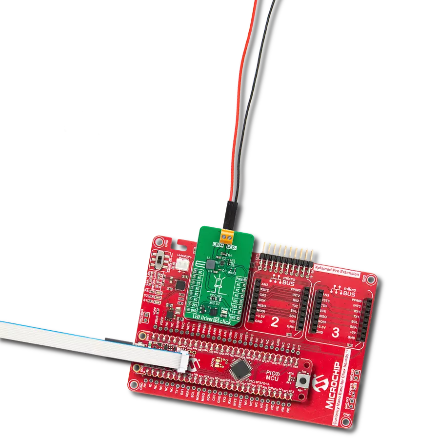
从选择您的开发板和Click板™开始。以Nucleo 64 with STM32F410RB MCU作为您的开发板开始。


实时跟踪您的结果
应用程序输出
1. 应用程序输出 - 在调试模式下,“应用程序输出”窗口支持实时数据监控,直接提供执行结果的可视化。请按照提供的教程正确配置环境,以确保数据正确显示。

2. UART 终端 - 使用UART Terminal通过USB to UART converter监视数据传输,实现Click board™与开发系统之间的直接通信。请根据项目需求配置波特率和其他串行设置,以确保正常运行。有关分步设置说明,请参考提供的教程。

3. Plot 输出 - Plot功能提供了一种强大的方式来可视化实时传感器数据,使趋势分析、调试和多个数据点的对比变得更加直观。要正确设置,请按照提供的教程,其中包含使用Plot功能显示Click board™读数的分步示例。在代码中使用Plot功能时,请使用以下函数:plot(insert_graph_name, variable_name);。这是一个通用格式,用户需要将“insert_graph_name”替换为实际图表名称,并将“variable_name”替换为要显示的参数。

软件支持
库描述
该库包含 LED Driver 5 Click 驱动程序的 API。
关键功能:
leddriver5_set_duty_cycle- 通用设置 PWM 占空比leddriver5_pwm_stop- 停止 PWM 模块leddriver5_pwm_start- 启动 PWM 模块
开源
代码示例
完整的应用程序代码和一个现成的项目可以通过NECTO Studio包管理器直接安装到NECTO Studio。 应用程序代码也可以在MIKROE的GitHub账户中找到。
/*!
 * @file
 * @brief LedDriver5 Click example
 *
 * # Description
 * The application is a capable of driving an array of high-power LEDs.
 *
 * The demo application is composed of two sections :
 *
 * ## Application Init
 * Initialization driver init and pwm init
 *
 * ## Application Task
 * This is an example that demonstrates the use of the LED Driver 5 Click board.
 * This example shows the automatic control of Led light intensity,
 * the first intensity of light is rising and then the intensity of light is falling.
 * Results are being sent to the Usart Terminal where you can track their changes.
 *
 *
 * @author Nikola Peric
 *
 */
// ------------------------------------------------------------------- INCLUDES

#include "board.h"
#include "log.h"
#include "leddriver5.h"

// ------------------------------------------------------------------ VARIABLES

static leddriver5_t leddriver5;
static log_t logger;

// ------------------------------------------------------ APPLICATION FUNCTIONS

void application_init ( void )
{
    log_cfg_t log_cfg;
    leddriver5_cfg_t cfg;

    /**
     * Logger initialization.
     * Default baud rate: 115200
     * Default log level: LOG_LEVEL_DEBUG
     * @note If USB_UART_RX and USB_UART_TX
     * are defined as HAL_PIN_NC, you will
     * need to define them manually for log to work.
     * See @b LOG_MAP_USB_UART macro definition for detailed explanation.
     */
    LOG_MAP_USB_UART( log_cfg );
    log_init( &logger, &log_cfg );
    log_info( &logger, "---- Application Init ----" );

    //  Click initialization.

    leddriver5_cfg_setup( &cfg );
    LEDDRIVER5_MAP_MIKROBUS( cfg, MIKROBUS_1 );
    leddriver5_init( &leddriver5, &cfg );

    leddriver5_pwm_start( &leddriver5 );
}

void application_task ( void )
{
    static int8_t duty_cnt = 1;
    static int8_t duty_inc = 1;
    float duty = duty_cnt / 10.0;

    leddriver5_set_duty_cycle( &leddriver5, duty );
    log_printf( &logger, "> Duty: %d%%\r\n", ( uint16_t )( duty_cnt * 10 ) );

    Delay_ms ( 500 );

    if ( 10 == duty_cnt )
    {
        duty_inc = -1;
    }
    else if ( 0 == duty_cnt )
    {
        duty_inc = 1;
    }
    duty_cnt += duty_inc;
}

int main ( void )
{
    /* Do not remove this line or clock might not be set correctly. */
    #ifdef PREINIT_SUPPORTED
    preinit();
    #endif

    application_init( );

    for ( ; ; )
    {
        application_task( );
    }

    return 0;
}


// ------------------------------------------------------------------------ END
额外支持
资源
类别:LED 驱动器