使用LLC解决方案和STM32F103RB弥合I2C设备之间的电压差距
提升逻辑水平:精确的I2C信号转换!

已发布 10月 08, 2024
点击板
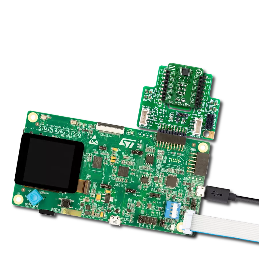
LLC-I2C Click
开发板
Nucleo 64 with STM32F103RB MCU
编译器
NECTO Studio
微控制器单元
STM32F103RB
为您的项目提供在 I2C 设备之间无缝转换逻辑电平的能力,优化通信,减少兼容性问题,并简化具有不同电压阈值的组件的集成。
A
A
硬件概览
它是如何工作的?
LLC-I2C Click 不使用集成电路 (IC),如前所述。完全避免使用 IC 带来了一些好处:LLC 电路的整体成本大大降低,更稳健的 MOSFET 解决方案降低了故障率,断电时,低电压侧和高电压侧彼此隔离(通过非导电的 MOSFET)。这种电路有时称为电平转换电路,当 I2C 从设备(通常是传感器 IC)在 I2C 通信中使用不同的逻辑电压电平时,通常需要这种电路。电路转换是双向的,使其适用于 I2C 通信协议。I2C 协议由 NXP Semiconductors(前身为 Philips Semiconductors)于 1982 年首次引入。他们还发布了一份应用说明,详细解释了 LLC
电路的操作。电路分为低侧和高侧部分,尽管电路是对称的,可用于双向。当没有通信时,MOSFET 的栅极和源极都被拉到其特定的参考电压水平。这将关闭两个 MOSFET,因为没有栅源电压差(例如,VG=VS=VSL)。由于 I2C 通过将其总线线断言为低电平逻辑来操作,当 MOSFET 一侧(例如高侧)的源极端子被驱动到低电平逻辑时,其 VGS 电位将上升,因为栅极电压是固定的。当 VGS 达到阈值电压(用于所用晶体管通常为 1.2V)时,MOSFET 将导通,通过另一侧(低侧)MOSFET 的体二极管导电,后者将变为直接偏置。该机制可用于在
所用 MOSFET 的整个工作范围内双向转换信号电平。高侧的参考电压可以通过标记为 VCC SEL 的 SMD 跳线选择。高侧的上拉电压可以从 mikroBUS™ 电源轨选择,因此可以是 3.3V 或 5V。对于低侧,可以将任意参考电压应用于 J1 接头的 VSL 引脚,尊重最大电压额定值。J1 是标准的 2.54mm 针脚接头。低侧 I2C 总线引脚也连接到 J1 接头,允许外部设备连接(使用标准导线跳线)。如前所述,低侧实际上可以使用比主设备更高的电压电平,但在大多数使用场景中,它将低于主设备,因此采用了这种术语。


功能概述
开发板
Nucleo-64 搭载 STM32F103RB MCU 提供了一种经济高效且灵活的平台,供开发者探索新想法并原型设计他们的项目。该板利用 STM32 微控制器的多功能性,使用户能够为他们的项目选择最佳的性能与功耗平衡。它配备了 LQFP64 封装的 STM32 微控制器,并包含了如用户 LED(同时作为 ARDUINO® 信号)、用户和复位按钮,以及 32.768kHz 晶体振荡器用于精确的计时操作等基本组件。Nucleo-64 板设计考虑到扩展性和灵活性,它特有的 ARDUINO® Uno
V3 扩展连接器和 ST morpho 扩展引脚头,提供了对 STM32 I/O 的完全访问,以实现全面的项目整合。电源供应选项灵活,支持 ST-LINK USB VBUS 或外部电源,确保在各种开发环境中的适应性。该板还配备了一个具有 USB 重枚举功能的板载 ST-LINK 调试器/编程器,简化了编程和调试过程。此外,该板设计旨在简化高级开发,它的外部 SMPS 为 Vcore 逻辑供电提供高效支持,支持 USB 设备全速或 USB SNK/UFP 全速,并内置加密功能,提升了项目的功效
和安全性。通过外部 SMPS 实验的专用连接器、 用于 ST-LINK 的 USB 连接器以及 MIPI® 调试连接器,提供了更多的硬件接口和实验可能性。开发者将通过 STM32Cube MCU Package 提供的全面免费软件库和示例得到广泛支持。这些,加上与多种集成开发环境(IDE)的兼容性,包括 IAR Embedded Workbench®、MDK-ARM 和 STM32CubeIDE,确保了流畅且高效的开发体验,使用户能够充分利用 Nucleo-64 板在他们的项目中的能力。

微控制器概述
MCU卡片 / MCU

建筑
ARM Cortex-M3
MCU 内存 (KB)
128
硅供应商
STMicroelectronics
引脚数
64
RAM (字节)
20480
你完善了我!
配件
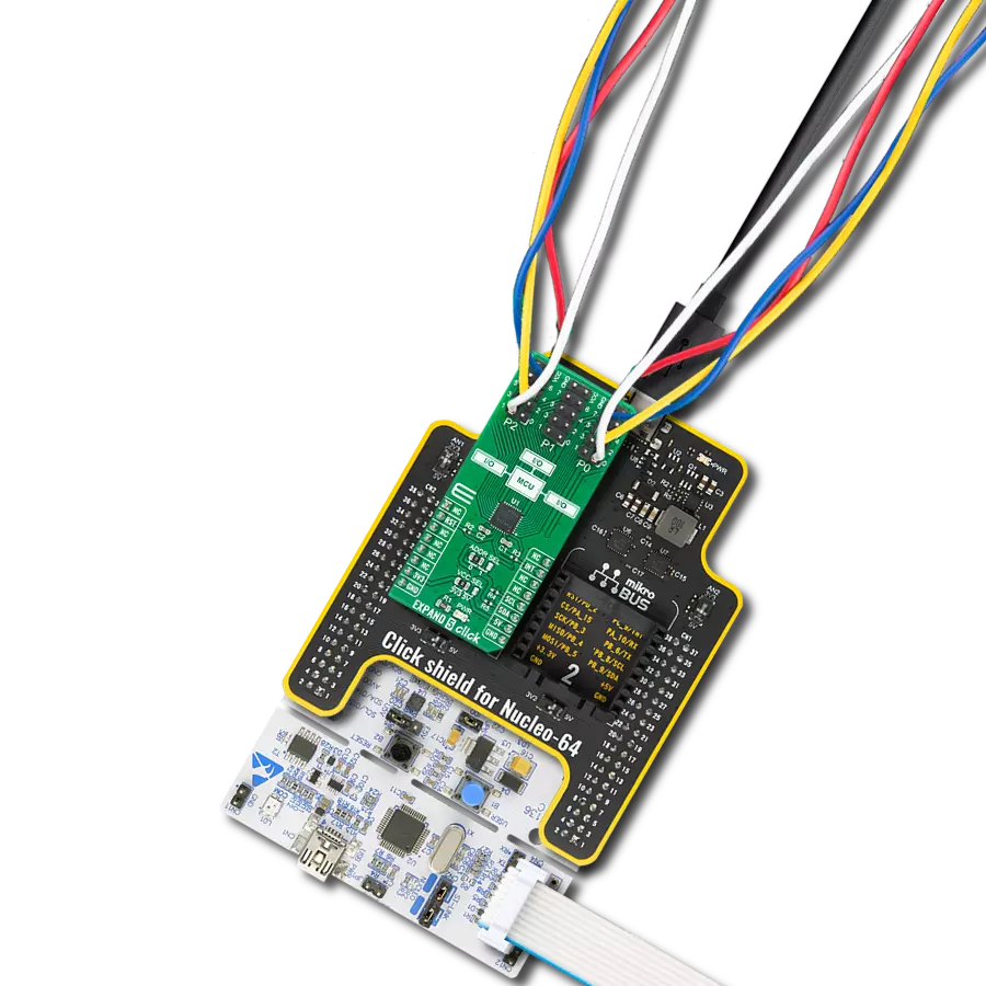
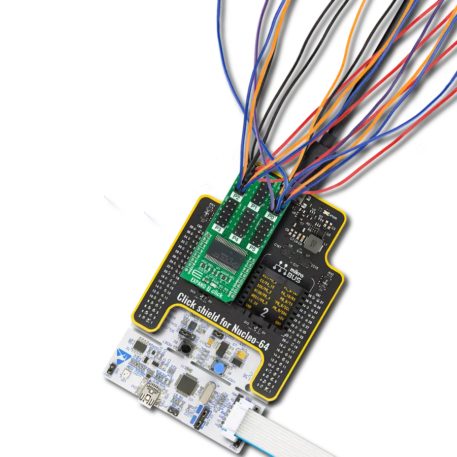
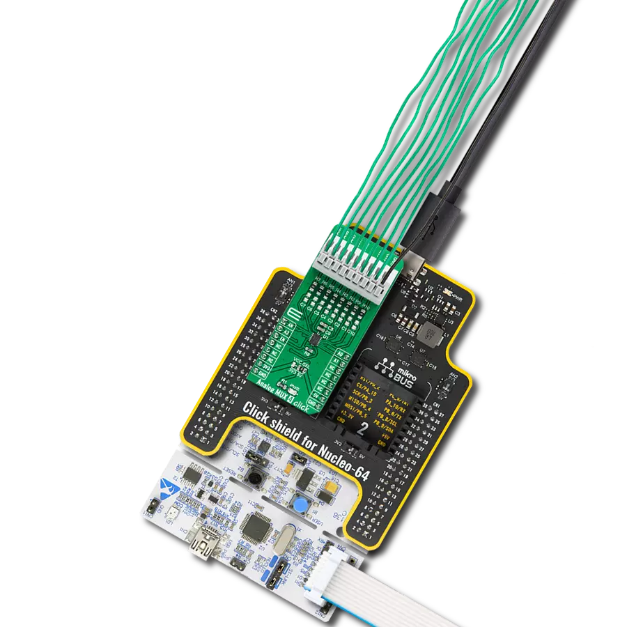
Click Shield for Nucleo-64 配备了两个专有的 mikroBUS™ 插座,使得所有的 Click board™ 设备都可以轻松地与 STM32 Nucleo-64 开发板连接。这样,Mikroe 允许其用户从不断增长的 Click boards™ 范围中添加任何功能,如 WiFi、GSM、GPS、蓝牙、ZigBee、环境传感器、LED、语音识别、电机控制、运动传感器等。您可以使用超过 1537 个 Click boards™,这些 Click boards™ 可以堆叠和集成。STM32 Nucleo-64 开发板基于 64 引脚封装的微控制器,采用 32 位 MCU,配备 ARM Cortex M4 处理器,运行速度为 84MHz,具有 512Kb Flash 和 96KB SRAM,分为两个区域,顶部区域代表 ST-Link/V2 调试器和编程器,而底部区域是一个实际的开发板。通过 USB 连接方便地控制和供电这些板子,以便直接对 Nucleo-64 开发板进行编程和高效调试,其中还需要额外的 USB 线连接到板子上的 USB 迷你接口。大多数 STM32 微控制器引脚都连接到了板子左右边缘的 IO 引脚上,然后连接到两个现有的 mikroBUS™ 插座上。该 Click Shield 还有几个开关,用于选择 mikroBUS™ 插座上模拟信号的逻辑电平和 mikroBUS™ 插座本身的逻辑电压电平。此外,用户还可以通过现有的双向电平转换器,使用任何 Click board™,无论 Click board™ 是否在 3.3V 或 5V 逻辑电压电平下运行。一旦将 STM32 Nucleo-64 开发板与我们的 Click Shield for Nucleo-64 连接,您就可以访问数百个工作于 3.3V 或 5V 逻辑电压电平的 Click boards™。

使用的MCU引脚
mikroBUS™映射器
“仔细看看!”
Click board™ 原理图

一步一步来
项目组装
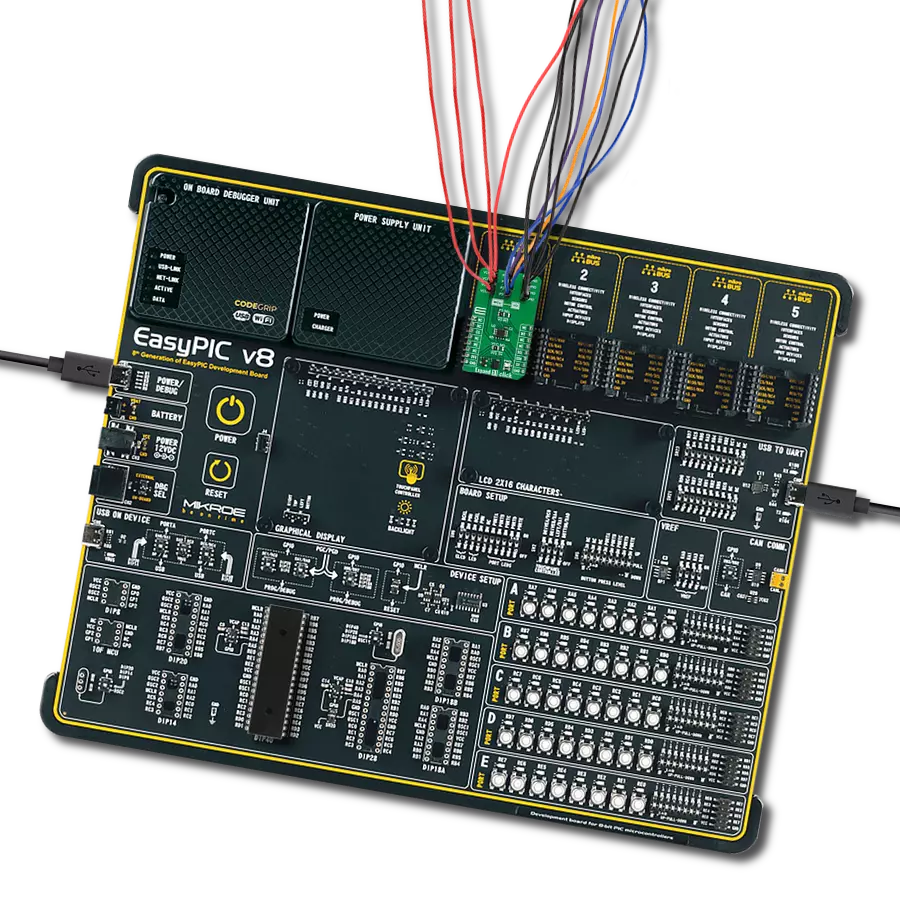
从选择您的开发板和Click板™开始。以Nucleo 64 with STM32F103RB MCU作为您的开发板开始。


软件支持
库描述
该库包含 LLC-I2C Click 驱动程序的 API。
关键功能:
llci2c_generic_write- 此函数向所需寄存器写入数据llci2c_generic_read- 此函数从所需寄存器读取数据
开源
代码示例
完整的应用程序代码和一个现成的项目可以通过NECTO Studio包管理器直接安装到NECTO Studio。 应用程序代码也可以在MIKROE的GitHub账户中找到。
/*!
 * \file
 * \brief LlcI2c Click example
 *
 * # Description
 * This Click can be utilized as the level converter for logic signals. The topology of this
 * logic level conversion (LLC) circuit is perfectly suited for the bi-directional I2C communication.
 *
 * The demo application is composed of two sections :
 *
 * ## Application Init
 * Initialization driver init
 *
 * ## Application Task
 * Reads the temperature from the Thermo 7 Click board and logs data to UART.
 *
 * *note:*
 * <pre>
 * Connection between Thermo 7 and I2C-LLC is made through I2C interface.
 * You can connect a Thermo 7 Click and I2C-LLC Click with the wires to make connection between Click boards.
 * We use the Thermo 7 Click to demonstrate the functions of the I2C-LLC Click.
 * </pre>
 *
 * \author MikroE Team
 *
 */
// ------------------------------------------------------------------- INCLUDES

#include "board.h"
#include "log.h"
#include "llci2c.h"

// ------------------------------------------------------------------ VARIABLES

static llci2c_t llci2c;
static log_t logger;

// ------------------------------------------------------ APPLICATION FUNCTIONS

void application_init ( void )
{
    log_cfg_t log_cfg;
    llci2c_cfg_t cfg;

    /**
     * Logger initialization.
     * Default baud rate: 115200
     * Default log level: LOG_LEVEL_DEBUG
     * @note If USB_UART_RX and USB_UART_TX
     * are defined as HAL_PIN_NC, you will
     * need to define them manually for log to work.
     * See @b LOG_MAP_USB_UART macro definition for detailed explanation.
     */
    LOG_MAP_USB_UART( log_cfg );
    log_init( &logger, &log_cfg );
    log_info( &logger, "---- Application Init ----" );

    //  Click initialization.

    llci2c_cfg_setup( &cfg );
    LLCI2C_MAP_MIKROBUS( cfg, MIKROBUS_1 );
    llci2c_init( &llci2c, &cfg );
}

void application_task ( void )
{
    // Thermo 7 measurement Temperature
    uint8_t write_reg = 0x00;
    uint8_t read_reg[ 2 ] = { 0 };

    float temp_msb;
    uint8_t temp_lsb;

    llci2c_generic_read ( &llci2c, write_reg, read_reg, 2 );

    temp_msb = read_reg[ 0 ];
    temp_lsb = read_reg[ 1 ] & 0xF0;

    if ( temp_lsb & 0x80 ) temp_msb += 0.50;
    if ( temp_lsb & 0x40 ) temp_msb += 0.25;
    if ( temp_lsb & 0x20 ) temp_msb += 0.125;
    if ( temp_lsb & 0x10 ) temp_msb += 0.0625;

    log_info( &logger, " Ambient temperature : %.2f C", temp_msb );
    Delay_ms ( 1000 );
}

int main ( void )
{
    /* Do not remove this line or clock might not be set correctly. */
    #ifdef PREINIT_SUPPORTED
    preinit();
    #endif

    application_init( );

    for ( ; ; )
    {
        application_task( );
    }

    return 0;
}


// ------------------------------------------------------------------------ END
额外支持
资源
类别:端口扩展器