使用M20071和STM32F446RE根据卫星信号确定精确的位置坐标
精确可靠的全球导航和定位解决方案

已发布 10月 08, 2024
点击板
GNSS 17 Click
开发板
Nucleo 64 with STM32F446RE MCU
编译器
NECTO Studio
微控制器单元
STM32F446RE
同时跟踪GPS、GLONASS、Galileo、BeiDou和QZSS卫星,以提高定位精度,尤其是在城市环境中
A
A
硬件概览
它是如何工作的?
GNSS 17 Click 基于 Antenova 的 M20071,这是一个集成全功能 GNSS 接收器模块。该模块包括 MediaTek AG3335MN 闪存芯片,能够同时跟踪多个 GNSS 星座,如 GPS、GLONASS、GALILEO、BEIDOU 和 QZSS。M20071 的高级多路径算法提高了定位精度,特别是在密集的城市环境中。此外,板载 LNA 确保在弱信号场景下表现出色,非常适合可穿戴设备。此 Click board™ 适用于多种应用,包括便携设备、资产跟踪、个人安全、运动电子和导航系统,提供可靠且精确的定位服务。M20071 还具有几个显著特性,增强了此板的功能。EPO(扩展预测轨道)快速修复功能允许模块使用长达 30 天的轨道预测,实现即时修复解决方案。EASY(自生成轨道预测)功能通过提供长达 3 天的 GPS 轨道预测,无需互联网连接或主处理器上的软件,加速 TTFF(首次定位时间)性能。此外,AIC(主动干扰消除)功能提供有效的窄带干扰消除,确保即使在挑战性环境中也能可靠和准确的 GNSS 性能。M20071 还提供三种
节能模式:关闭、RTC 和周期。在关闭模式下,通过 mikroBUS™ 插座的 EN 引脚控制,模块仅保持电源管理逻辑激活,当 EN 引脚处于低逻辑状态时,所有其他逻辑电路断电。RTC 模式,通过 mikroBUS™ 插座的 RTC 引脚管理,是一种低功耗状态,关闭系统核心。此模式下模块不能发送命令或提供与位置相关的信息,但它会将导航数据保存到 RTC-RAM。唤醒后,模块使用这些保存的数据快速重新获取位置修复。周期模式是一种用户可配置状态,模块在运行和睡眠之间交替,减少电流消耗,同时保持更新的数据。这种灵活性允许用户根据特定的功耗和性能需求调整模块的操作。M20071 模块和主机 MCU 通过 UART 接口进行通信,使用标准 UART RX 和 TX 引脚。默认通信速度设置为 115200bps,确保高效的数据交换。除了 UART TX 和 RX 引脚外,板上还使用 RTS 引脚与主机 MCU 进行握手,以防止丢失命令。此外,GNSS 17 Click 包括一个绿色 PPS LED 指示灯,每秒从 M20071 发出一个同步脉冲信号。此脉冲
信号的默认宽度为 100 ms,但可以配置在 50 ms 到 999 ms 之间。PPS 功能默认启用,一旦达到 3D 修复,模块将输出 PPS 信号。M20071 不需要特定的上电顺序,但其系统核心需要 1.8V 电压才能正常工作。为实现这一点,两个小型 AP2112 LDO 稳压器从 mikroBUS™ 电源轨提供必要的 1.8V 电压,为 M20071 及其 GNSS 天线供电。除了 mikroBUS™ 电源轨外,此板还支持从板背面附加的纽扣电池提供备用电源。负责 GNSS 天线供电的稳压器可以通过 mikroBUS™ 插座的 AON 引脚激活。此 Click board™ 可以通过 VCC SEL 跳线选择使用 3.3V 或 5V 逻辑电压水平。由于 M20071 模块在 1.8V 下工作,使用逻辑电平转换器 TXB0106 以实现正确操作和精确的信号电平转换。因此,3.3V 和 5V 兼容的 MCU 都可以正确使用通信线路。此外,这款 Click board™ 配备了包含易用功能的库和示例代码,可作为进一步开发的参考。

功能概述
开发板
Nucleo-64 搭载 STM32F446RE MCU 提供了一种经济高效且灵活的平台,供开发者探索新想法并原型设计他们的项目。该板利用 STM32 微控制器的多功能性,使用户能够为他们的项目选择最佳的性能与功耗平衡。它配备了 LQFP64 封装的 STM32 微控制器,并包含了如用户 LED(同时作为 ARDUINO® 信号)、用户和复位按钮,以及 32.768kHz 晶体振荡器用于精确的计时操作等基本组件。Nucleo-64 板设计考虑到扩展性和灵活性,它特有的 ARDUINO® Uno
V3 扩展连接器和 ST morpho 扩展引脚头,提供了对 STM32 I/O 的完全访问,以实现全面的项目整合。电源供应选项灵活,支持 ST-LINK USB VBUS 或外部电源,确保在各种开发环境中的适应性。该板还配备了一个具有 USB 重枚举功能的板载 ST-LINK 调试器/编程器,简化了编程和调试过程。此外,该板设计旨在简化高级开发,它的外部 SMPS 为 Vcore 逻辑供电提供高效支持,支持 USB 设备全速或 USB SNK/UFP 全速,并内置加密功能,提升了项目的功效
和安全性。通过外部 SMPS 实验的专用连接器、 用于 ST-LINK 的 USB 连接器以及 MIPI® 调试连接器,提供了更多的硬件接口和实验可能性。开发者将通过 STM32Cube MCU Package 提供的全面免费软件库和示例得到广泛支持。这些,加上与多种集成开发环境(IDE)的兼容性,包括 IAR Embedded Workbench®、MDK-ARM 和 STM32CubeIDE,确保了流畅且高效的开发体验,使用户能够充分利用 Nucleo-64 板在他们的项目中的能力。

微控制器概述
MCU卡片 / MCU

建筑
ARM Cortex-M4
MCU 内存 (KB)
512
硅供应商
STMicroelectronics
引脚数
64
RAM (字节)
131072
你完善了我!
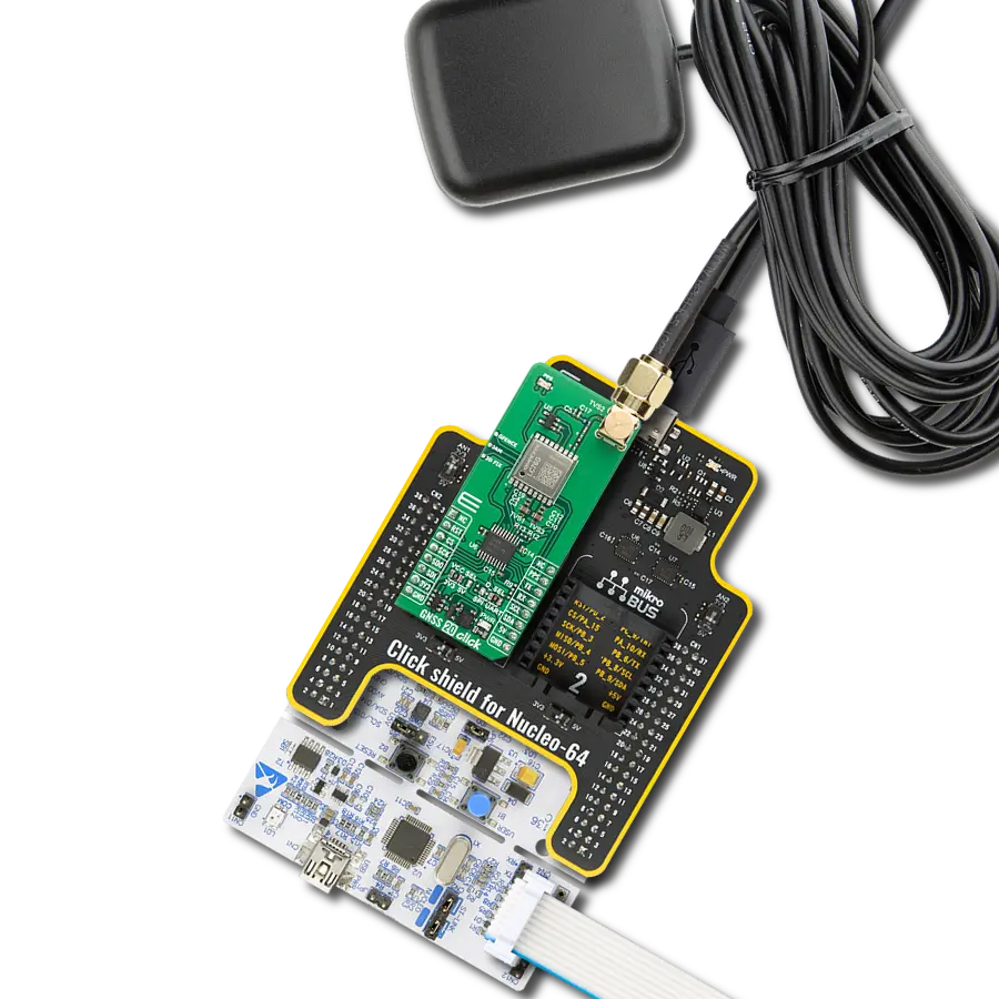
配件
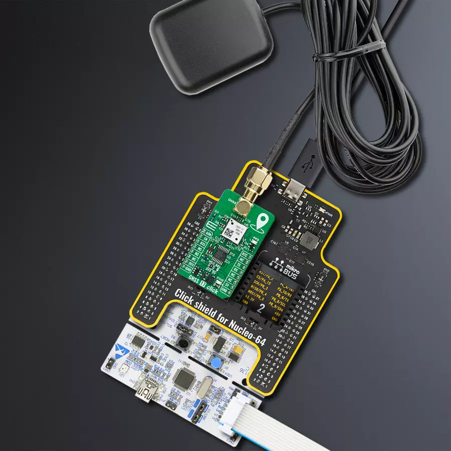
Click Shield for Nucleo-64 配备了两个专有的 mikroBUS™ 插座,使得所有的 Click board™ 设备都可以轻松地与 STM32 Nucleo-64 开发板连接。这样,Mikroe 允许其用户从不断增长的 Click boards™ 范围中添加任何功能,如 WiFi、GSM、GPS、蓝牙、ZigBee、环境传感器、LED、语音识别、电机控制、运动传感器等。您可以使用超过 1537 个 Click boards™,这些 Click boards™ 可以堆叠和集成。STM32 Nucleo-64 开发板基于 64 引脚封装的微控制器,采用 32 位 MCU,配备 ARM Cortex M4 处理器,运行速度为 84MHz,具有 512Kb Flash 和 96KB SRAM,分为两个区域,顶部区域代表 ST-Link/V2 调试器和编程器,而底部区域是一个实际的开发板。通过 USB 连接方便地控制和供电这些板子,以便直接对 Nucleo-64 开发板进行编程和高效调试,其中还需要额外的 USB 线连接到板子上的 USB 迷你接口。大多数 STM32 微控制器引脚都连接到了板子左右边缘的 IO 引脚上,然后连接到两个现有的 mikroBUS™ 插座上。该 Click Shield 还有几个开关,用于选择 mikroBUS™ 插座上模拟信号的逻辑电平和 mikroBUS™ 插座本身的逻辑电压电平。此外,用户还可以通过现有的双向电平转换器,使用任何 Click board™,无论 Click board™ 是否在 3.3V 或 5V 逻辑电压电平下运行。一旦将 STM32 Nucleo-64 开发板与我们的 Click Shield for Nucleo-64 连接,您就可以访问数百个工作于 3.3V 或 5V 逻辑电压电平的 Click boards™。

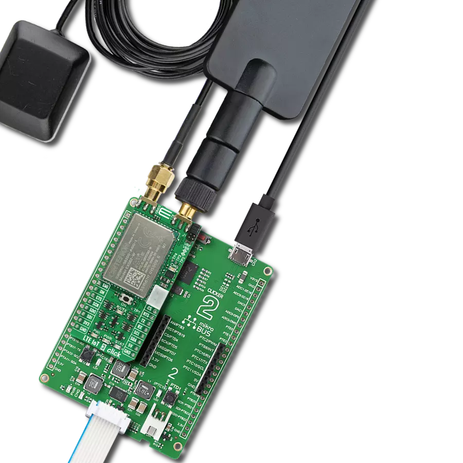
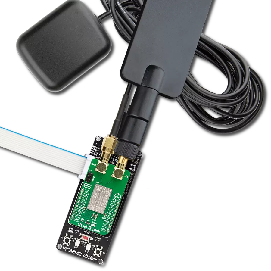
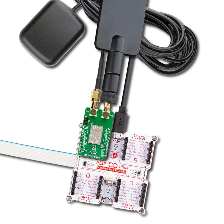
主动 GPS 天线旨在增强您的 GPS 和 GNSS Click 板™ 的性能。这款外置天线结构坚固,适用于各种天气条件。凭借 1575.42MHz 的频率范围和 50Ohm 的阻抗,它确保了可靠的信号接收。天线在较宽的角度范围内提供大于 -4dBic 的增益,确保超过 75% 的覆盖率。± 5MHz 的带宽进一步保证了精确的数据采集。天线采用右旋圆极化 (RHCP),提供稳定的信号接收。其紧凑的尺寸为 48.5×39×15mm,配有 2 米长的电缆,安装方便。磁性天线类型与 SMA 公连接器确保了安全便捷的连接。如果您需要为定位设备提供可靠的外置天线,我们的主动 GPS 天线是完美的解决方案。

使用的MCU引脚
mikroBUS™映射器
“仔细看看!”
Click board™ 原理图

一步一步来
项目组装
从选择您的开发板和Click板™开始。以Nucleo 64 with STM32F446RE MCU作为您的开发板开始。


软件支持
库描述
该库包含 NAME Click 驱动程序的 API。
关键功能:
gnss17_generic_read- 此函数通过使用UART串行接口读取所需数量的数据字节。gnss17_parse_gga- 此函数从读取的响应缓冲区解析GGA数据。gnss17_reset_device- 此函数通过切换EN和AON引脚来重置设备。
开源
代码示例
完整的应用程序代码和一个现成的项目可以通过NECTO Studio包管理器直接安装到NECTO Studio。 应用程序代码也可以在MIKROE的GitHub账户中找到。
/*!
 * @file main.c
 * @brief GNSS 17 Click Example.
 *
 * # Description
 * This example demonstrates the use of GNSS 17 Click by reading and displaying
 * the GNSS coordinates.
 *
 * The demo application is composed of two sections :
 *
 * ## Application Init
 * Initializes the driver and resets the Click board.
 *
 * ## Application Task
 * Reads the received data, parses the NMEA GGA info from it, and once it receives
 * the position fix it will start displaying the coordinates on the USB UART.
 *
 * ## Additional Function
 * - static void gnss17_clear_app_buf ( void )
 * - static void gnss17_log_app_buf ( void )
 * - static err_t gnss17_process ( gnss17_t *ctx )
 * - static void gnss17_parser_application ( uint8_t *rsp )
 *
 * @author Stefan Filipovic
 *
 */

#include "board.h"
#include "log.h"
#include "gnss17.h"

// Application buffer size
#define APP_BUFFER_SIZE             500
#define PROCESS_BUFFER_SIZE         200

static gnss17_t gnss17;
static log_t logger;

static uint8_t app_buf[ APP_BUFFER_SIZE ] = { 0 };
static int32_t app_buf_len = 0;

/**
 * @brief GNSS 17 clearing application buffer.
 * @details This function clears memory of application buffer and reset its length.
 * @note None.
 */
static void gnss17_clear_app_buf ( void );

/**
 * @brief GNSS 17 log application buffer.
 * @details This function logs data from application buffer to USB UART.
 * @note None.
 */
static void gnss17_log_app_buf ( void );

/**
 * @brief GNSS 17 data reading function.
 * @details This function reads data from device and concatenates data to application buffer.
 * @param[in] ctx : Click context object.
 * See #gnss17_t object definition for detailed explanation.
 * @return @li @c  0 - Read some data.
 *         @li @c -1 - Nothing is read.
 * See #err_t definition for detailed explanation.
 * @note None.
 */
static err_t gnss17_process ( gnss17_t *ctx );

/**
 * @brief GNSS 17 parser application.
 * @param[in] rsp Response buffer.
 * @details This function logs GNSS data on the USB UART.
 * @return None.
 * @note None.
 */
static void gnss17_parser_application ( uint8_t *rsp );

void application_init ( void )
{
    log_cfg_t log_cfg;  /**< Logger config object. */
    gnss17_cfg_t gnss17_cfg;  /**< Click config object. */

    /**
     * Logger initialization.
     * Default baud rate: 115200
     * Default log level: LOG_LEVEL_DEBUG
     * @note If USB_UART_RX and USB_UART_TX
     * are defined as HAL_PIN_NC, you will
     * need to define them manually for log to work.
     * See @b LOG_MAP_USB_UART macro definition for detailed explanation.
     */
    LOG_MAP_USB_UART( log_cfg );
    log_init( &logger, &log_cfg );
    log_info( &logger, " Application Init " );

    // Click initialization.
    gnss17_cfg_setup( &gnss17_cfg );
    GNSS17_MAP_MIKROBUS( gnss17_cfg, MIKROBUS_1 );
    if ( UART_ERROR == gnss17_init( &gnss17, &gnss17_cfg ) )
    {
        log_error( &logger, " Communication init." );
        for ( ; ; );
    }

    log_info( &logger, " Application Task " );
}

void application_task ( void )
{
    if ( GNSS17_OK == gnss17_process( &gnss17 ) )
    {
        if ( app_buf_len > ( sizeof ( GNSS17_RSP_GGA ) + GNSS17_GGA_ELEMENT_SIZE ) )
        {
            gnss17_parser_application( app_buf );
        }
    }
}

int main ( void )
{
    /* Do not remove this line or clock might not be set correctly. */
    #ifdef PREINIT_SUPPORTED
    preinit();
    #endif

    application_init( );

    for ( ; ; )
    {
        application_task( );
    }

    return 0;
}

static void gnss17_clear_app_buf ( void )
{
    memset( app_buf, 0, app_buf_len );
    app_buf_len = 0;
}

static void gnss17_log_app_buf ( void )
{
    for ( int32_t buf_cnt = 0; buf_cnt < app_buf_len; buf_cnt++ )
    {
        log_printf( &logger, "%c", app_buf[ buf_cnt ] );
    }
}

static err_t gnss17_process ( gnss17_t *ctx )
{
    uint8_t rx_buf[ PROCESS_BUFFER_SIZE ] = { 0 };
    int32_t overflow_bytes = 0;
    int32_t rx_cnt = 0;
    int32_t rx_size = gnss17_generic_read( ctx, rx_buf, PROCESS_BUFFER_SIZE );
    if ( ( rx_size > 0 ) && ( rx_size <= APP_BUFFER_SIZE ) )
    {
        if ( ( app_buf_len + rx_size ) > APP_BUFFER_SIZE )
        {
            overflow_bytes = ( app_buf_len + rx_size ) - APP_BUFFER_SIZE;
            app_buf_len = APP_BUFFER_SIZE - rx_size;
            memmove ( app_buf, &app_buf[ overflow_bytes ], app_buf_len );
            memset ( &app_buf[ app_buf_len ], 0, overflow_bytes );
        }
        for ( rx_cnt = 0; rx_cnt < rx_size; rx_cnt++ )
        {
            if ( rx_buf[ rx_cnt ] )
            {
                app_buf[ app_buf_len++ ] = rx_buf[ rx_cnt ];
            }
        }
        return GNSS17_OK;
    }
    return GNSS17_ERROR;
}

static void gnss17_parser_application ( uint8_t *rsp )
{
    uint8_t element_buf[ 200 ] = { 0 };
    if ( GNSS17_OK == gnss17_parse_gga( rsp, GNSS17_GGA_LATITUDE, element_buf ) )
    {
        static uint8_t wait_for_fix_cnt = 0;
        if ( strlen( element_buf ) > 0 )
        {
            log_printf( &logger, "\r\n Latitude: %.2s degrees, %s minutes \r\n", element_buf, &element_buf[ 2 ] );
            memset( element_buf, 0, sizeof( element_buf ) );
            gnss17_parse_gga( rsp, GNSS17_GGA_LONGITUDE, element_buf );
            log_printf( &logger, " Longitude: %.3s degrees, %s minutes \r\n", element_buf, &element_buf[ 3 ] );
            memset( element_buf, 0, sizeof( element_buf ) );
            gnss17_parse_gga( rsp, GNSS17_GGA_ALTITUDE, element_buf );
            log_printf( &logger, " Altitude: %s m \r\n", element_buf );
            wait_for_fix_cnt = 0;
        }
        else
        {
            if ( wait_for_fix_cnt % 5 == 0 )
            {
                log_printf( &logger, " Waiting for the position fix...\r\n\n" );
                wait_for_fix_cnt = 0;
            }
            wait_for_fix_cnt++;
        }
        gnss17_clear_app_buf(  );
    }
}

// ------------------------------------------------------------------------ END
额外支持
资源
类别:GPS/GNSS