使用TLC5947和STM32F031K6实现惊艳的色彩混合
点亮您的生活,照亮您的世界

已发布 10月 01, 2024
点击板
LED Driver 18 Click
开发板
Nucleo 32 with STM32F031K6 MCU
编译器
NECTO Studio
微控制器单元
STM32F031K6
相信我们可靠且创新的 LED 驱动解决方案,它能为您的照明项目注入活力,为您的所有 LED 照明需求提供无与伦比的性能和效率。
A
A
硬件概览
它是如何工作的?
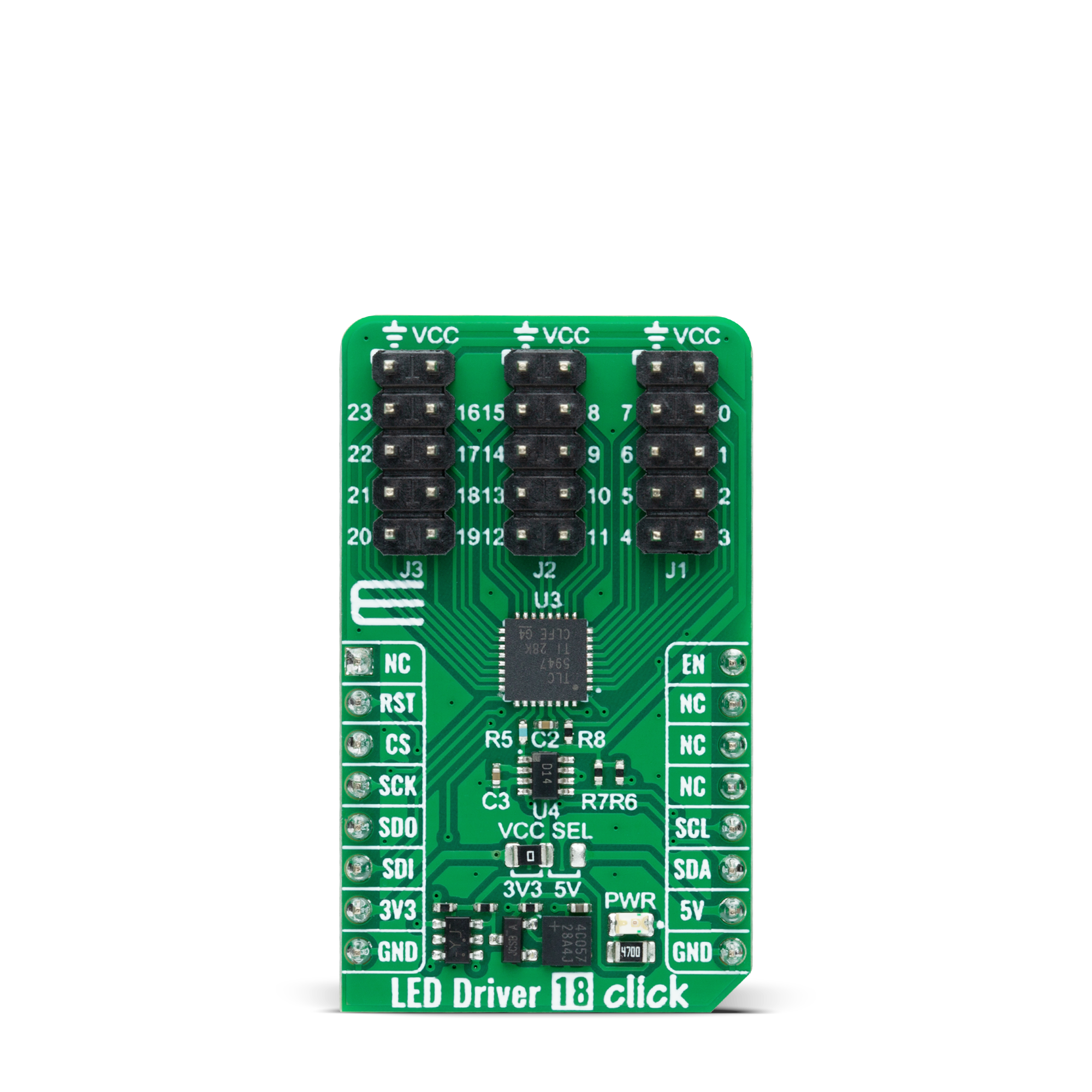
LED Driver 18 Click 基于 TLC5947,这是来自德州仪器的 24 通道 12 位 PWM LED 驱动器。每个通道支持多个串联连接到 LED 端子的 LED,并通过串行接口端口具有可单独调节的 4096 步 PWM 灰度亮度控制。所有 24 个通道的可编程电流值通过 AD5171(一种 I2C 可配置的数字电位器)实现,每个通道的最大 LED 电流为 30mA。TLC5947 还具有内置的热关断功能,在过温条件下关闭所有输出驱动
器。当温度恢复正常时,所有通道自动重新启动。LED Driver 18 Click 通过寄存器可选择的标准 SPI 接口与 MCU 通信,支持高达 30MHz 的高时钟速度以获得最佳性能。除了接口信号外,TLC5947 还使用 mikroBUS™ 插座的另一个信号。路由到 mikroBUS™ 插座的 EN 引脚的使能信号提供关闭所有恒流输出的能力。当 EN 引脚处于高电平状态时,所有通道(0-23)被强制关闭,灰度 PWM 计时控
制器初始化,灰度计数器复位为 0。当 EN 引脚处于低电平状态时,灰度 PWM 计时控制器控制所有 LED 通道。此 Click board™ 可以在 3.3V 或 5V 逻辑电压水平下运行,通过 VCC SEL 跳线选择。这样,3.3V 和 5V 的 MCU 都可以正确使用通信线路。此外,该 Click board™ 配备了包含易于使用的函数和示例代码的库,可作为进一步开发的参考。
功能概述
开发板
Nucleo 32开发板搭载STM32F031K6 MCU,提供了一种经济且灵活的平台,适用于使用32引脚封装的STM32微控制器进行实验。该开发板具有Arduino™ Nano连接性,便于通过专用扩展板进行功能扩展,并且支持mbed,使其能够无缝集成在线资源。板载集成
ST-LINK/V2-1调试器/编程器,支持通过USB重新枚举,提供三种接口:虚拟串口(Virtual Com port)、大容量存储和调试端口。该开发板的电源供应灵活,可通过USB VBUS或外部电源供电。此外,还配备了三个LED指示灯(LD1用于USB通信,LD2用于电源
指示,LD3为用户可控LED)和一个复位按钮。STM32 Nucleo-32开发板支持多种集成开发环境(IDEs),如IAR™、Keil®和基于GCC的IDE(如AC6 SW4STM32),使其成为开发人员的多功能工具。

微控制器概述
MCU卡片 / MCU

建筑
ARM Cortex-M0
MCU 内存 (KB)
32
硅供应商
STMicroelectronics
引脚数
32
RAM (字节)
4096
你完善了我!
配件
Click Shield for Nucleo-32是扩展您的开发板功能的理想选择,专为STM32 Nucleo-32引脚布局设计。Click Shield for Nucleo-32提供了两个mikroBUS™插座,可以添加来自我们不断增长的Click板™系列中的任何功能。从传感器和WiFi收发器到电机控制和音频放大器,我们应有尽有。Click Shield for Nucleo-32与STM32 Nucleo-32开发板兼容,为用户提供了一种经济且灵活的方式,使用任何STM32微控制器快速创建原型,并尝试各种性能、功耗和功能的组合。STM32 Nucleo-32开发板无需任何独立的探针,因为它集成了ST-LINK/V2-1调试器/编程器,并随附STM32全面的软件HAL库和各种打包的软件示例。这个开发平台为用户提供了一种简便且通用的方式,将STM32 Nucleo-32兼容开发板与他们喜欢的Click板™结合,应用于即将开展的项目中。

使用的MCU引脚
mikroBUS™映射器
“仔细看看!”
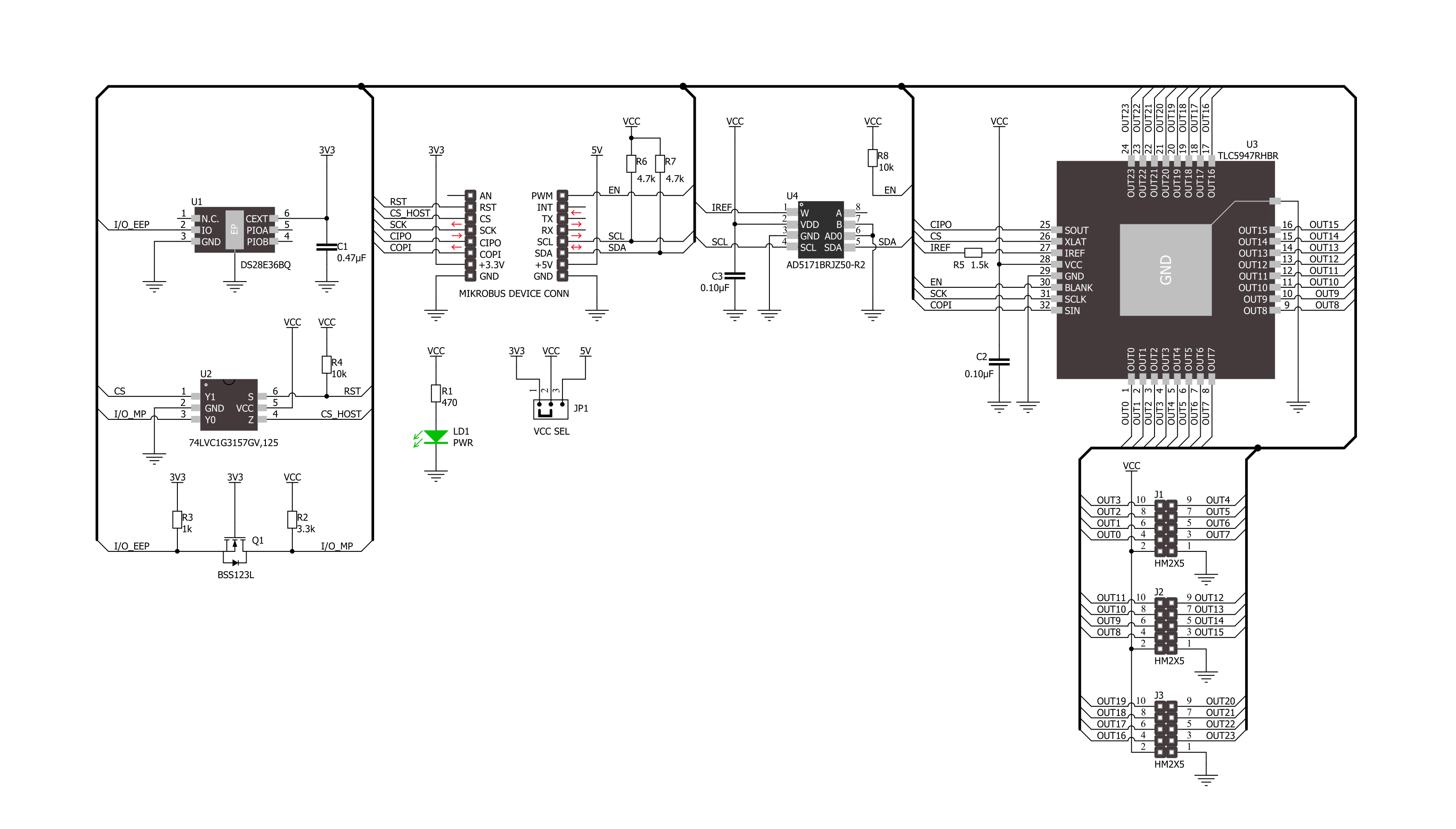
Click board™ 原理图
一步一步来
项目组装

从选择您的开发板和Click板™开始。以Nucleo 32 with STM32F031K6 MCU作为您的开发板开始。


实时跟踪您的结果
应用程序输出
1. 应用程序输出 - 在调试模式下,“应用程序输出”窗口支持实时数据监控,直接提供执行结果的可视化。请按照提供的教程正确配置环境,以确保数据正确显示。

2. UART 终端 - 使用UART Terminal通过USB to UART converter监视数据传输,实现Click board™与开发系统之间的直接通信。请根据项目需求配置波特率和其他串行设置,以确保正常运行。有关分步设置说明,请参考提供的教程。

3. Plot 输出 - Plot功能提供了一种强大的方式来可视化实时传感器数据,使趋势分析、调试和多个数据点的对比变得更加直观。要正确设置,请按照提供的教程,其中包含使用Plot功能显示Click board™读数的分步示例。在代码中使用Plot功能时,请使用以下函数:plot(insert_graph_name, variable_name);。这是一个通用格式,用户需要将“insert_graph_name”替换为实际图表名称,并将“variable_name”替换为要显示的参数。

软件支持
库描述
该库包含 LED Driver 18 Click 驱动程序的 API。
关键功能:
leddriver18_set_output_pwm- LED Driver 18 设置输出通道 PWM 值功能leddriver18_write_config- LED Driver 18 写入配置功能leddriver18_set_cc_output- LED Driver 18 设置恒流输出功能
开源
代码示例
完整的应用程序代码和一个现成的项目可以通过NECTO Studio包管理器直接安装到NECTO Studio。 应用程序代码也可以在MIKROE的GitHub账户中找到。
/*!
 * @file main.c
 * @brief LED Driver 18 Click example
 *
 * # Description
 * This library contains API for LED Driver 18 Click driver.
 * The library initializes and defines the I2C bus drivers to
 * write and read data for setting constant current output,
 * as well as the default configuration for a PWM output value
 * of the OUT pins.
 *
 * The demo application is composed of two sections :
 *
 * ## Application Init
 * Initializes the driver and performs default configuration and sets
 * the device in output enabled mode.
 *
 * ## Application Task
 * This example demonstrates the use of the LED Driver 18 Click board by
 * changing PWM values for all output from a minimum value to
 * maximum value and back to minimum controlling the brightness of the
 * LEDs in the process.
 *
 * @author Stefan Ilic
 *
 */

#include "board.h"
#include "log.h"
#include "leddriver18.h"

static leddriver18_t leddriver18;
static log_t logger;

void application_init ( void )
{
    log_cfg_t log_cfg;  /**< Logger config object. */
    leddriver18_cfg_t leddriver18_cfg;  /**< Click config object. */

    /**
     * Logger initialization.
     * Default baud rate: 115200
     * Default log level: LOG_LEVEL_DEBUG
     * @note If USB_UART_RX and USB_UART_TX
     * are defined as HAL_PIN_NC, you will
     * need to define them manually for log to work.
     * See @b LOG_MAP_USB_UART macro definition for detailed explanation.
     */
    LOG_MAP_USB_UART( log_cfg );
    log_init( &logger, &log_cfg );
    log_info( &logger, " Application Init " );

    // Click initialization.
    leddriver18_cfg_setup( &leddriver18_cfg );
    LEDDRIVER18_MAP_MIKROBUS( leddriver18_cfg, MIKROBUS_1 );
    if ( I2C_MASTER_ERROR == leddriver18_init( &leddriver18, &leddriver18_cfg ) )
    {
        log_error( &logger, " Communication init." );
        for ( ; ; );
    }

    if ( LEDDRIVER18_ERROR == leddriver18_default_cfg ( &leddriver18 ) )
    {
        log_error( &logger, " Default configuration." );
        for ( ; ; );
    }

    log_info( &logger, " Application Task " );
}

void application_task ( void )
{
    float pwm_val;

    for ( int8_t  n_cnt = 0; n_cnt <= 100; n_cnt += 10 )
    {
        for ( uint8_t out_cnt = 0; out_cnt < LEDDRIVER18_MAX_OUTPUT_NUM; out_cnt++ )
        {
            leddriver18_set_output_pwm( out_cnt, n_cnt );
        }
        pwm_val = leddriver18_get_output_pwm( 0 );
        log_printf( &logger, " PWM value: %.2f \r\n", pwm_val );
        leddriver18_write_config( &leddriver18 );
        Delay_ms( 200 );
    }
    for ( int8_t  n_cnt = 100; n_cnt >= 10; n_cnt -= 10 )
    {
        for ( uint8_t out_cnt = 0; out_cnt < LEDDRIVER18_MAX_OUTPUT_NUM; out_cnt++ )
        {
            leddriver18_set_output_pwm( out_cnt, n_cnt );
        }
        pwm_val = leddriver18_get_output_pwm( 0 );
        log_printf( &logger, " PWM value: %.2f \r\n", pwm_val );
        leddriver18_write_config( &leddriver18 );
        Delay_ms( 200 );
    }
}

void main ( void )
{
    application_init( );

    for ( ; ; )
    {
        application_task( );
    }
}

// ------------------------------------------------------------------------ END


