使用ADM2763E和STM32F031K6扩展您的网络超越边界
全面隔离的力量:重新定义RS485通信

已发布 10月 01, 2024
点击板
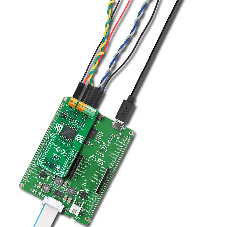
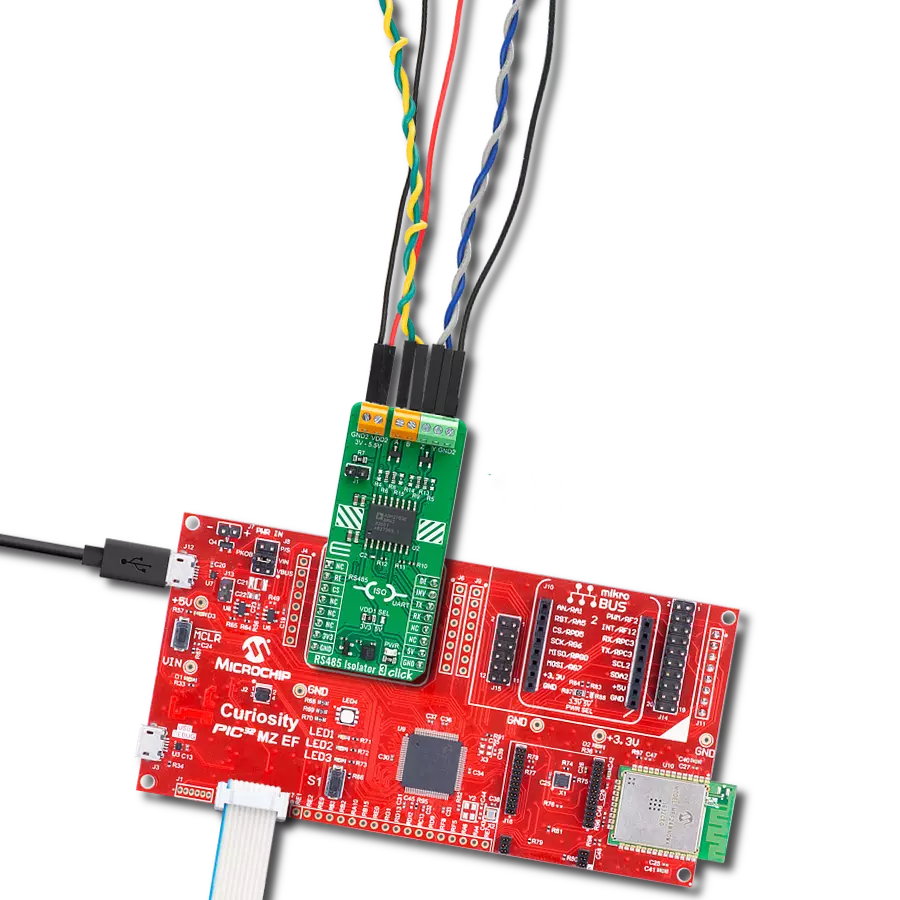
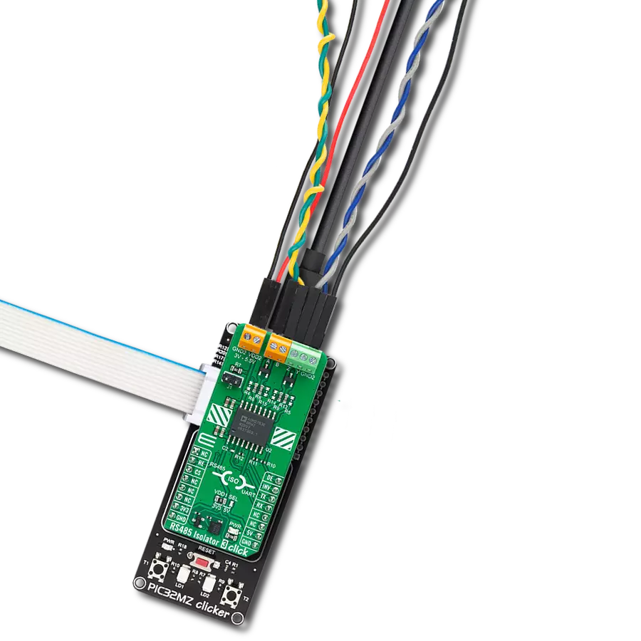
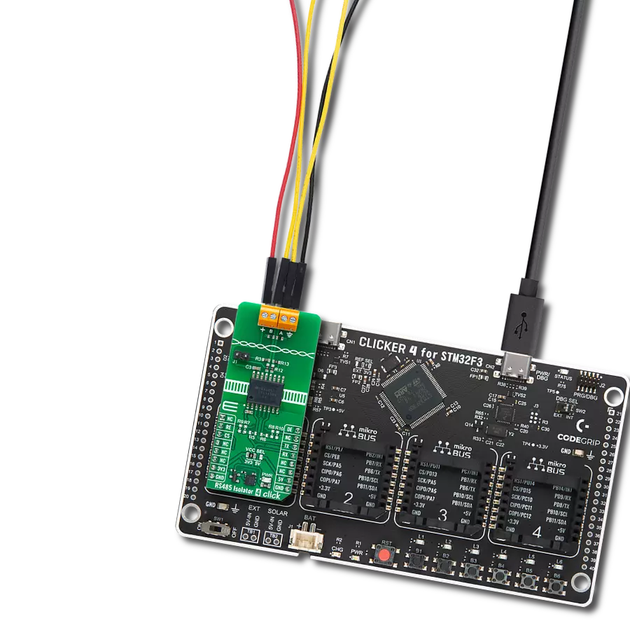
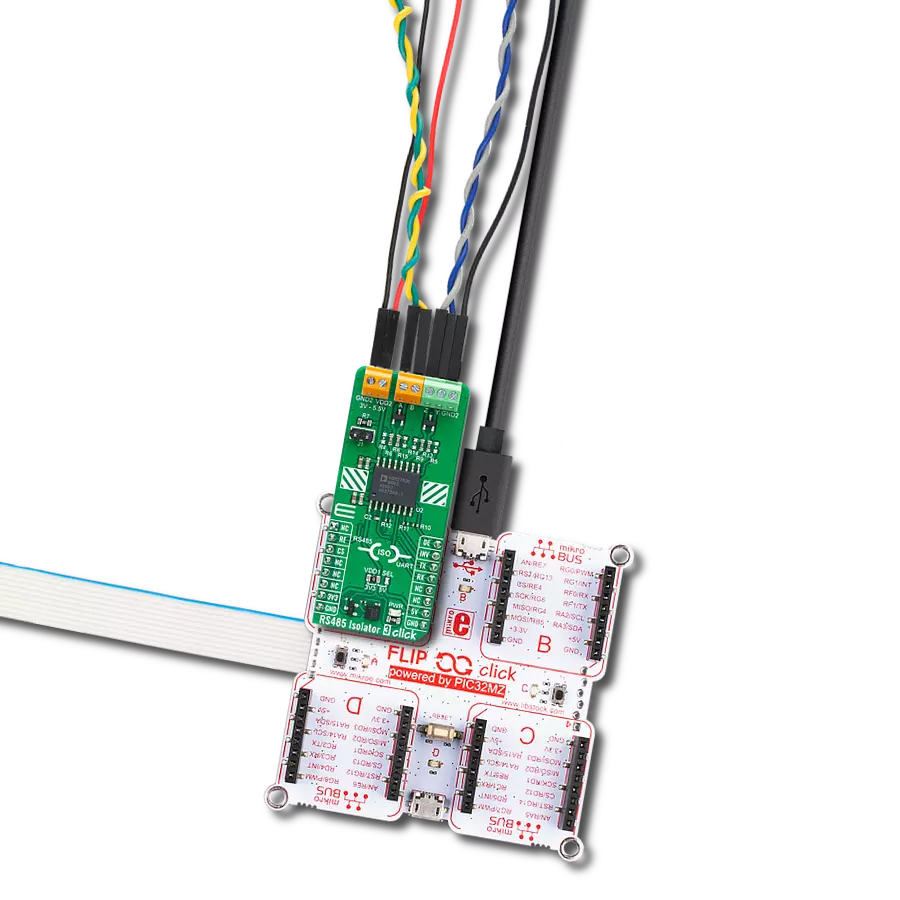
RS485 Isolator 3 Click
开发板
Nucleo 32 with STM32F031K6 MCU
编译器
NECTO Studio
微控制器单元
STM32F031K6
释放您的RS485网络潜力,采用完全隔离技术,彻底改变您的通信方式,确保数据完整性达到前所未有的水平。
A
A
硬件概览
它是如何工作的?
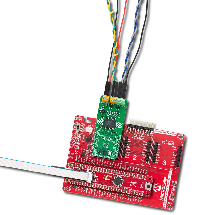
RS485 Isolator 3 Click基于Analog Devices的5.7kV RMS信号隔离RS-485收发器ADM2763E。ADM2763E针对长电缆运行的低速进行了优化,最大数据速率为500kbps。它在RS485接收器和驱动器端子引脚上受保护,符合IEC 61000-4-2标准的≥±12 kV接触和≥±15 kV空气静电放电(ESD)事件,并通过螺钉端子块轻松访问。ADM2763E具有四个总线信号:非反向输入信号的信号A,反向输入信号的信号B,非反向输出信号的信号Y和反向输出信号的信号Z,以及一个公共接地连接。使用具有开关键控调制方案的共面变压器线圈可以实现ADM2763E隔离屏障上的高数据吞吐量,同时最小化辐射发射。这样的架
构为数字隔离器提供了在设备的全温度和电源范围内>250 kV/μs的共模瞬态抗扰度。ADM2763E还具有专有的发射器架构,具有低驱动器输出阻抗,可以增加差分输出电压。高差分输出电压扩展了ADM2763E的传输距离,使该板适用于在隔离侧供电为5V时的PROFIBUS®节点(隔离侧提供3V到5.5V范围内的电源电压可能性)。除了mikroBUS™插槽上常用的UART TX和RX引脚外,该板还具有路由到mikroBUS™插槽的RE和DE引脚的接收器和驱动器使能引脚。它还具有接收器电缆反转引脚,路由到mikroBUS™插槽的INV引脚,以便在保持完整接收器故障安全性能的同时快速校正A和B接收器总线引脚上的
反转电缆连接。此外,ADM2763E还具有内置的接收器总线空闲状态故障保护,可通过一些未填充的板载跳线访问(ADM2763E引脚A和Y上的R4和R5上拉电阻,以及引脚B和Z上的R14和R15下拉电阻连接到GND2公共接地)。如果用户将此板连接到需要总线外部偏置电阻的其他设备,则可以安装这些电阻。ADM2763E还具有一个跳线,允许通过在其上放置跳线帽来为RS485接收器添加120Ω负载。该Click板可以通过VDD1 SEL跳线选择3.3V或5V逻辑电压电平,从而使3.3V和5V的MCU都能正确使用通信线路。此外,它配备了一个包含易于使用的函数和示例代码的库,可作为进一步开发的参考。

功能概述
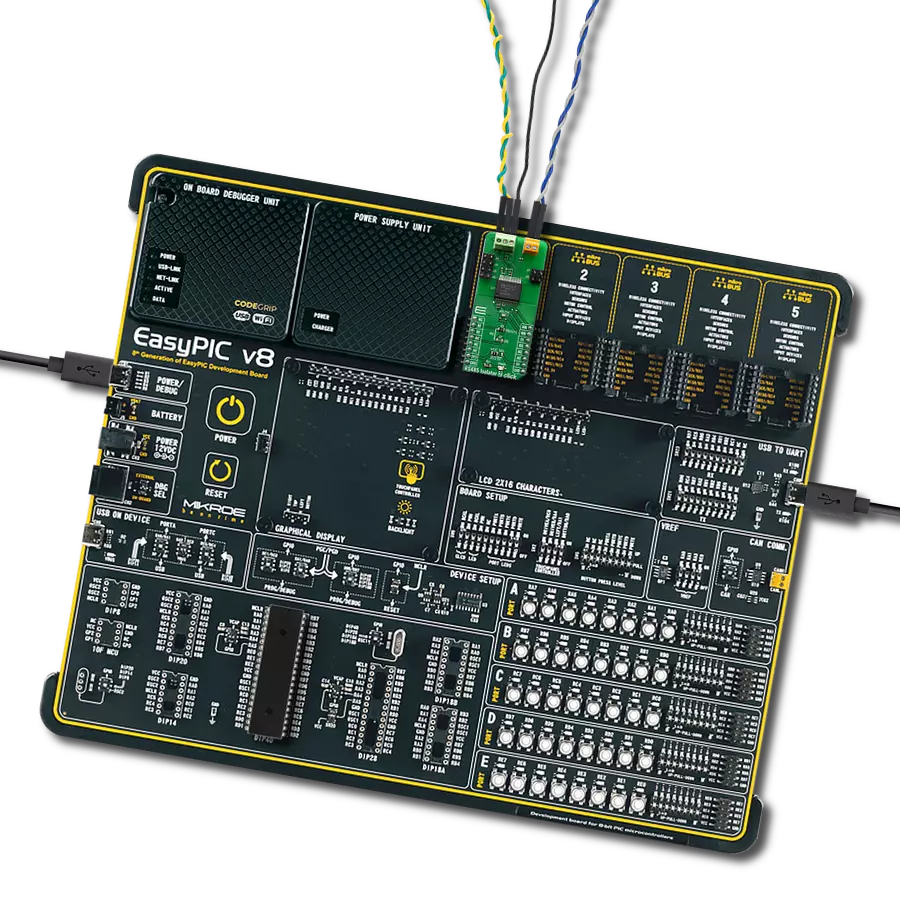
开发板
Nucleo 32开发板搭载STM32F031K6 MCU,提供了一种经济且灵活的平台,适用于使用32引脚封装的STM32微控制器进行实验。该开发板具有Arduino™ Nano连接性,便于通过专用扩展板进行功能扩展,并且支持mbed,使其能够无缝集成在线资源。板载集成
ST-LINK/V2-1调试器/编程器,支持通过USB重新枚举,提供三种接口:虚拟串口(Virtual Com port)、大容量存储和调试端口。该开发板的电源供应灵活,可通过USB VBUS或外部电源供电。此外,还配备了三个LED指示灯(LD1用于USB通信,LD2用于电源
指示,LD3为用户可控LED)和一个复位按钮。STM32 Nucleo-32开发板支持多种集成开发环境(IDEs),如IAR™、Keil®和基于GCC的IDE(如AC6 SW4STM32),使其成为开发人员的多功能工具。

微控制器概述
MCU卡片 / MCU

建筑
ARM Cortex-M0
MCU 内存 (KB)
32
硅供应商
STMicroelectronics
引脚数
32
RAM (字节)
4096
你完善了我!
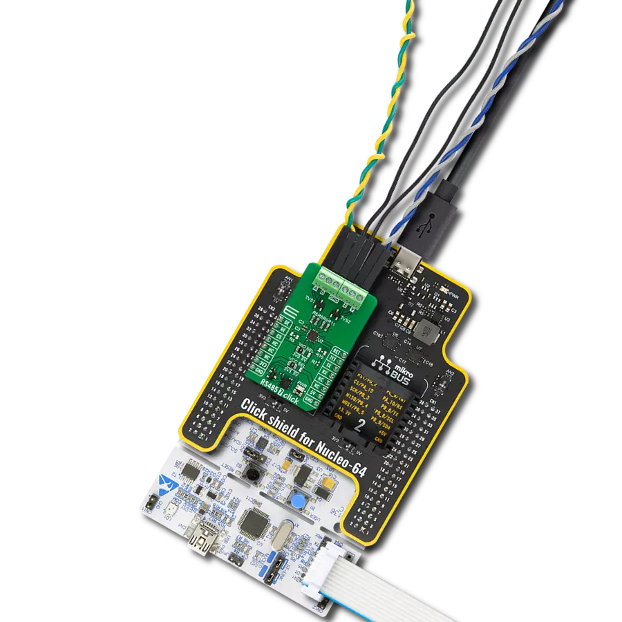
配件
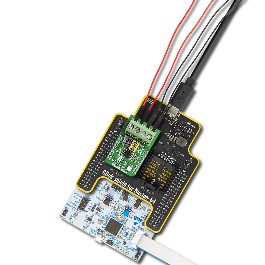
Click Shield for Nucleo-32是扩展您的开发板功能的理想选择,专为STM32 Nucleo-32引脚布局设计。Click Shield for Nucleo-32提供了两个mikroBUS™插座,可以添加来自我们不断增长的Click板™系列中的任何功能。从传感器和WiFi收发器到电机控制和音频放大器,我们应有尽有。Click Shield for Nucleo-32与STM32 Nucleo-32开发板兼容,为用户提供了一种经济且灵活的方式,使用任何STM32微控制器快速创建原型,并尝试各种性能、功耗和功能的组合。STM32 Nucleo-32开发板无需任何独立的探针,因为它集成了ST-LINK/V2-1调试器/编程器,并随附STM32全面的软件HAL库和各种打包的软件示例。这个开发平台为用户提供了一种简便且通用的方式,将STM32 Nucleo-32兼容开发板与他们喜欢的Click板™结合,应用于即将开展的项目中。

使用的MCU引脚
mikroBUS™映射器
“仔细看看!”
Click board™ 原理图

一步一步来
项目组装

从选择您的开发板和Click板™开始。以Nucleo 32 with STM32F031K6 MCU作为您的开发板开始。


实时跟踪您的结果
应用程序输出
1. 应用程序输出 - 在调试模式下,“应用程序输出”窗口支持实时数据监控,直接提供执行结果的可视化。请按照提供的教程正确配置环境,以确保数据正确显示。

2. UART 终端 - 使用UART Terminal通过USB to UART converter监视数据传输,实现Click board™与开发系统之间的直接通信。请根据项目需求配置波特率和其他串行设置,以确保正常运行。有关分步设置说明,请参考提供的教程。

3. Plot 输出 - Plot功能提供了一种强大的方式来可视化实时传感器数据,使趋势分析、调试和多个数据点的对比变得更加直观。要正确设置,请按照提供的教程,其中包含使用Plot功能显示Click board™读数的分步示例。在代码中使用Plot功能时,请使用以下函数:plot(insert_graph_name, variable_name);。这是一个通用格式,用户需要将“insert_graph_name”替换为实际图表名称,并将“variable_name”替换为要显示的参数。

软件支持
库描述
该库包含 RS485 Isolator 3 Click 驱动程序的 API。
关键功能:
rs485isolator3_enable_receiver_input- RS485 Isolator 3 启用接收器输入功能rs485isolator3_disable_receiver_input- RS485 Isolator 3 禁用接收器输入功能rs485isolator3_disable_output- RS485 Isolator 3 禁用输出功能
开源
代码示例
完整的应用程序代码和一个现成的项目可以通过NECTO Studio包管理器直接安装到NECTO Studio。 应用程序代码也可以在MIKROE的GitHub账户中找到。
/*!
 * @file main.c
 * @brief RS485 Isolator 3 Click Example.
 *
 * # Description
 * This example reads and processes data from RS485 Isolator 3 Clicks.
 *
 * The demo application is composed of two sections :
 *
 * ## Application Init
 * Initializes the driver and enables the selected mode.
 *
 * ## Application Task
 * Depending on the selected mode, it reads all the received data or sends the desired message
 * every 2 seconds.
 *
 * ## Additional Function
 * - static err_t rs485isolator3_process ( void )
 *
 * @author Stefan Ilic
 *
 */

#include "board.h"
#include "log.h"
#include "rs485isolator3.h"

#define PROCESS_BUFFER_SIZE 200

#define DEMO_APP_RECEIVER
// #define DEMO_APP_TRANSMITTER

static rs485isolator3_t rs485isolator3;
static log_t logger;

uint8_t data_buf[ 8 ] = { 'M', 'i', 'k', 'r', 'o', 'E', '\r', '\n' };

/**
 * @brief RS485 Isolator 3 data reading function.
 * @details This function reads data from device and concatenates data to application buffer.
 * @return @li @c  0 - Read some data.
 *         @li @c -1 - Nothing is read.
 * See #err_t definition for detailed explanation.
 * @note None.
 */
static err_t rs485isolator3_process ( void );

void application_init ( void )
{
    log_cfg_t log_cfg;  /**< Logger config object. */
    rs485isolator3_cfg_t rs485isolator3_cfg;  /**< Click config object. */

    /**
     * Logger initialization.
     * Default baud rate: 115200
     * Default log level: LOG_LEVEL_DEBUG
     * @note If USB_UART_RX and USB_UART_TX
     * are defined as HAL_PIN_NC, you will
     * need to define them manually for log to work.
     * See @b LOG_MAP_USB_UART macro definition for detailed explanation.
     */
    LOG_MAP_USB_UART( log_cfg );
    log_init( &logger, &log_cfg );
    log_info( &logger, " Application Init " );

    // Click initialization.
    rs485isolator3_cfg_setup( &rs485isolator3_cfg );
    RS485ISOLATOR3_MAP_MIKROBUS( rs485isolator3_cfg, MIKROBUS_1 );
    if ( UART_ERROR == rs485isolator3_init( &rs485isolator3, &rs485isolator3_cfg ) )
    {
        log_error( &logger, " Communication init." );
        for ( ; ; );
    }

    rs485isolator3_default_cfg ( &rs485isolator3 );

#ifdef DEMO_APP_RECEIVER
    rs485isolator3_enable_receiver_input( &rs485isolator3 );
    rs485isolator3_disable_output( &rs485isolator3 );
    log_info( &logger, "---- Receiver mode ----" );
#endif
#ifdef DEMO_APP_TRANSMITTER
    rs485isolator3_disable_receiver_input( &rs485isolator3 );
    rs485isolator3_enable_output( &rs485isolator3 );
    log_info( &logger, "---- Transmitter mode ----" );
#endif

    log_info( &logger, " Application Task " );
    Delay_ms ( 100 );
}

void application_task ( void )
{
#ifdef DEMO_APP_RECEIVER
    rs485isolator3_process( );
#endif

#ifdef DEMO_APP_TRANSMITTER
    rs485isolator3_generic_write( &rs485isolator3, data_buf, strlen( data_buf ) );
    log_info( &logger, "---- Data sent ----" );
    Delay_ms ( 1000 );
    Delay_ms ( 1000 );
#endif
}

int main ( void )
{
    /* Do not remove this line or clock might not be set correctly. */
    #ifdef PREINIT_SUPPORTED
    preinit();
    #endif

    application_init( );

    for ( ; ; )
    {
        application_task( );
    }

    return 0;
}

static err_t rs485isolator3_process ( void )
{
    int32_t rx_size;
    char rx_buf[ PROCESS_BUFFER_SIZE ] = { 0 };
    rx_size = rs485isolator3_generic_read( &rs485isolator3, rx_buf, PROCESS_BUFFER_SIZE );
    if ( rx_size > 0 )
    {
        log_printf( &logger, "%s", rx_buf );
        return RS485ISOLATOR3_OK;
    }
    return RS485ISOLATOR3_ERROR;
}

// ------------------------------------------------------------------------ END