使用ISO7741和STM32F031K6为您的项目提供SPI隔离
信号隔离的无声英雄

已发布 10月 01, 2024
点击板
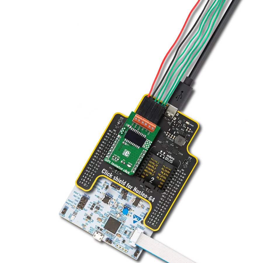
SPI Isolator 2 Click
开发板
Nucleo 32 with STM32F031K6 MCU
编译器
NECTO Studio
微控制器单元
STM32F031K6
使用我们的SPI隔离器,您可以有效地断开电路不同部分之间的电气连接,防止干扰、噪声和电压不匹配,这些问题可能会中断数据传输。
A
A
硬件概览
它是如何工作的?
SPI Isolator 2 Click基于ISO7741,这是一款由德州仪器提供的高性能四通道数字隔离器,能够实现高达5000Vrms的电隔离。它在低功耗下提供高电磁抗扰度和低辐射,同时隔离数字I/O。该模块具有三个正向通道和一个反向通道,为隔离的SPI数据通信提供了紧凑的解决方案。每个隔离通道都有一个逻辑输入和输出缓冲器,由双电容二氧化硅绝缘屏障隔开。ISO7741数字隔离器使用单端CMOS逻辑切换技术,通过隔离屏障传输数字数据。发射器通过隔离屏障发送高频载波来表示一种数字状态,不发送信号来表示另一
种数字状态。经过高级信号调理后,接收器解调信号并通过缓冲级产生输出。如果启用引脚处于低逻辑状态,输出信号将进入高阻抗状态。SPI Isolator 2 Click通过SPI串行接口与MCU通信,最大数据速率为100 Mbps。此Click板™还配备了两侧各两个使能引脚,可用于将各自的输出置于高阻抗状态,以便进行多主驱动应用并降低功耗。ISO7741数字侧的使能引脚标记为EN1,连接到mikroBUS™插座的RST引脚,而另一使能引脚连接到隔离侧的外部连接器,标记为EN2。除了连接到隔离SPI数据通信线路的连接器外,
此Click板™还有另一个外部电源供应终端。电压范围为2.25V至5.5V,适用于3.3V和5V的MCU。ISO7741还可以阻挡高电压,隔离地线,并防止数据总线或其他电路上的噪声电流进入本地地线并损坏敏感电路。此Click板™可以通过VCC SEL跳线选择使用3.3V或5V逻辑电压水平。这样,3.3V和5V的MCU都可以正确使用通信线路。此外,这款Click板™配备了一个包含易用函数和示例代码的库,可用作进一步开发的参考。


功能概述
开发板
Nucleo 32开发板搭载STM32F031K6 MCU,提供了一种经济且灵活的平台,适用于使用32引脚封装的STM32微控制器进行实验。该开发板具有Arduino™ Nano连接性,便于通过专用扩展板进行功能扩展,并且支持mbed,使其能够无缝集成在线资源。板载集成
ST-LINK/V2-1调试器/编程器,支持通过USB重新枚举,提供三种接口:虚拟串口(Virtual Com port)、大容量存储和调试端口。该开发板的电源供应灵活,可通过USB VBUS或外部电源供电。此外,还配备了三个LED指示灯(LD1用于USB通信,LD2用于电源
指示,LD3为用户可控LED)和一个复位按钮。STM32 Nucleo-32开发板支持多种集成开发环境(IDEs),如IAR™、Keil®和基于GCC的IDE(如AC6 SW4STM32),使其成为开发人员的多功能工具。

微控制器概述
MCU卡片 / MCU

建筑
ARM Cortex-M0
MCU 内存 (KB)
32
硅供应商
STMicroelectronics
引脚数
32
RAM (字节)
4096
你完善了我!
配件
Click Shield for Nucleo-32是扩展您的开发板功能的理想选择,专为STM32 Nucleo-32引脚布局设计。Click Shield for Nucleo-32提供了两个mikroBUS™插座,可以添加来自我们不断增长的Click板™系列中的任何功能。从传感器和WiFi收发器到电机控制和音频放大器,我们应有尽有。Click Shield for Nucleo-32与STM32 Nucleo-32开发板兼容,为用户提供了一种经济且灵活的方式,使用任何STM32微控制器快速创建原型,并尝试各种性能、功耗和功能的组合。STM32 Nucleo-32开发板无需任何独立的探针,因为它集成了ST-LINK/V2-1调试器/编程器,并随附STM32全面的软件HAL库和各种打包的软件示例。这个开发平台为用户提供了一种简便且通用的方式,将STM32 Nucleo-32兼容开发板与他们喜欢的Click板™结合,应用于即将开展的项目中。

使用的MCU引脚
mikroBUS™映射器
“仔细看看!”
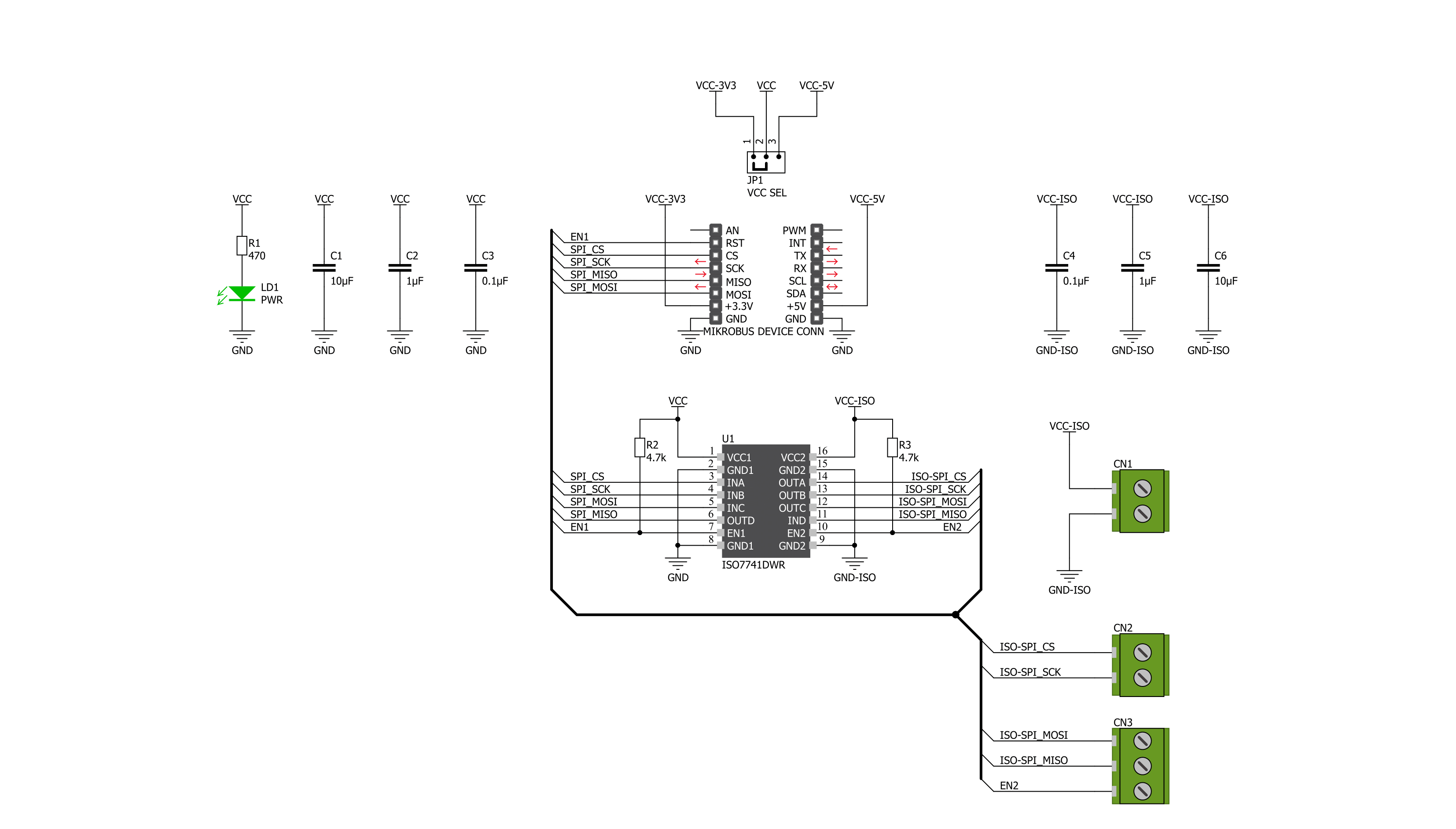
Click board™ 原理图
一步一步来
项目组装

从选择您的开发板和Click板™开始。以Nucleo 32 with STM32F031K6 MCU作为您的开发板开始。


实时跟踪您的结果
应用程序输出
1. 应用程序输出 - 在调试模式下,“应用程序输出”窗口支持实时数据监控,直接提供执行结果的可视化。请按照提供的教程正确配置环境,以确保数据正确显示。

2. UART 终端 - 使用UART Terminal通过USB to UART converter监视数据传输,实现Click board™与开发系统之间的直接通信。请根据项目需求配置波特率和其他串行设置,以确保正常运行。有关分步设置说明,请参考提供的教程。

3. Plot 输出 - Plot功能提供了一种强大的方式来可视化实时传感器数据,使趋势分析、调试和多个数据点的对比变得更加直观。要正确设置,请按照提供的教程,其中包含使用Plot功能显示Click board™读数的分步示例。在代码中使用Plot功能时,请使用以下函数:plot(insert_graph_name, variable_name);。这是一个通用格式,用户需要将“insert_graph_name”替换为实际图表名称,并将“variable_name”替换为要显示的参数。

软件支持
库描述
该库包含 SPI Isolator 2 Click 驱动程序的 API。
关键功能:
spiisolator2_output_enable- 该功能启用或禁用ISO7741的输出(隔离)spiisolator2_set_cmd- 该功能向ISO7741发送所需命令spiisolator2_write_byte- 该功能将数据字节写入ISO7741的目标8位寄存器地址
开源
代码示例
完整的应用程序代码和一个现成的项目可以通过NECTO Studio包管理器直接安装到NECTO Studio。 应用程序代码也可以在MIKROE的GitHub账户中找到。
/*!
 * @file main.c
 * @brief SPIIsolator2 Click example
 *
 * # Description
 * This is an example that demonstrates the use of the SPI Isolator 2 click board.
 * This board uses the ISO7741 which provides high electromagnetic immunity and low
 * emissions at low power consumption while isolating digital I/Os. In this example,
 * we write and then read data from the connected EEPROM 5 click to the SPI Isolator 2
 * click board.
 *
 * The demo application is composed of two sections :
 *
 * ## Application Init
 * Initializes SPI, begins to write log, set write/read memory address, enable output.
 *
 * ## Application Task
 * Enables write to EEPROM, then writes the specified text message, and reads it back.
 * All data is being displayed on the USB UART where you can track the program flow.
 *
 * @author Jelena Milosavljevic
 *
 */

#include "board.h"
#include "log.h"
#include "spiisolator2.h"

static spiisolator2_t spiisolator2;
static log_t logger;
static uint8_t demo_data[ 7 ] = { 'M', 'i', 'k', 'r', 'o', 'E', 0 };
static uint8_t read_data[ 7 ] = { 0 };
static uint32_t memory_address = 1234;

void application_init ( void )
{
    log_cfg_t log_cfg;                         /**< Logger config object. */
    spiisolator2_cfg_t spiisolator2_cfg;       /**< Click config object. */

    /**
     * Logger initialization.
     * Default baud rate: 115200
     * Default log level: LOG_LEVEL_DEBUG
     * @note If USB_UART_RX and USB_UART_TX
     * are defined as HAL_PIN_NC, you will
     * need to define them manually for log to work.
     * See @b LOG_MAP_USB_UART macro definition for detailed explanation.
     */
    LOG_MAP_USB_UART( log_cfg );
    log_init( &logger, &log_cfg );
    log_info( &logger, " Application Init " );

    // Click initialization.
    spiisolator2_cfg_setup( &spiisolator2_cfg );
    SPIISOLATOR2_MAP_MIKROBUS( spiisolator2_cfg, MIKROBUS_1 );
    if ( SPI_MASTER_ERROR == spiisolator2_init( &spiisolator2, &spiisolator2_cfg ) )
    {
        log_error( &logger, " Application Init Error. \r\n" );
        log_info( &logger, " Please, run program again... \r\n" );
        for ( ; ; );
    }
    Delay_ms( 100 );

    spiisolator2_output_enable( &spiisolator2, SPIISOLATOR2_OUT_ENABLE );
    log_info( &logger, " Application Task " );
    Delay_ms( 100 );
}

void application_task ( void )
{
    spiisolator2_set_cmd( &spiisolator2, SPIISOLATOR2_EEPROM5_CMD_WREN );
    Delay_ms( 10 );

    spiisolator2_multi_write( &spiisolator2,
                              ( ( uint32_t ) SPIISOLATOR2_EEPROM5_CMD_WRITE << 24 ) | memory_address, 4, demo_data, 7 );
    log_printf( &logger," Write data : %s\r\n", demo_data );
    log_printf( &logger, "- - - - - - - - - - -\r\n" );
    Delay_ms( 100 );

    spiisolator2_multi_read( &spiisolator2,
                             ( ( uint32_t ) SPIISOLATOR2_EEPROM5_CMD_READ << 24 ) | memory_address, 4, read_data, 7 );
    Delay_ms( 1000 );

    log_printf( &logger, " Read data  : %s\r\n", read_data );
    log_printf( &logger, "---------------------\r\n" );
    Delay_ms( 5000 );
}

void main ( void )
{
    application_init( );

    for ( ; ; )
    {
        application_task( );
    }
}

// ------------------------------------------------------------------------ END