使用 DWM3000 和 STM32F031K6 以位置精度的黄金标准赋能您的项目
超越预期的精度
已发布 10月 01, 2024
点击板
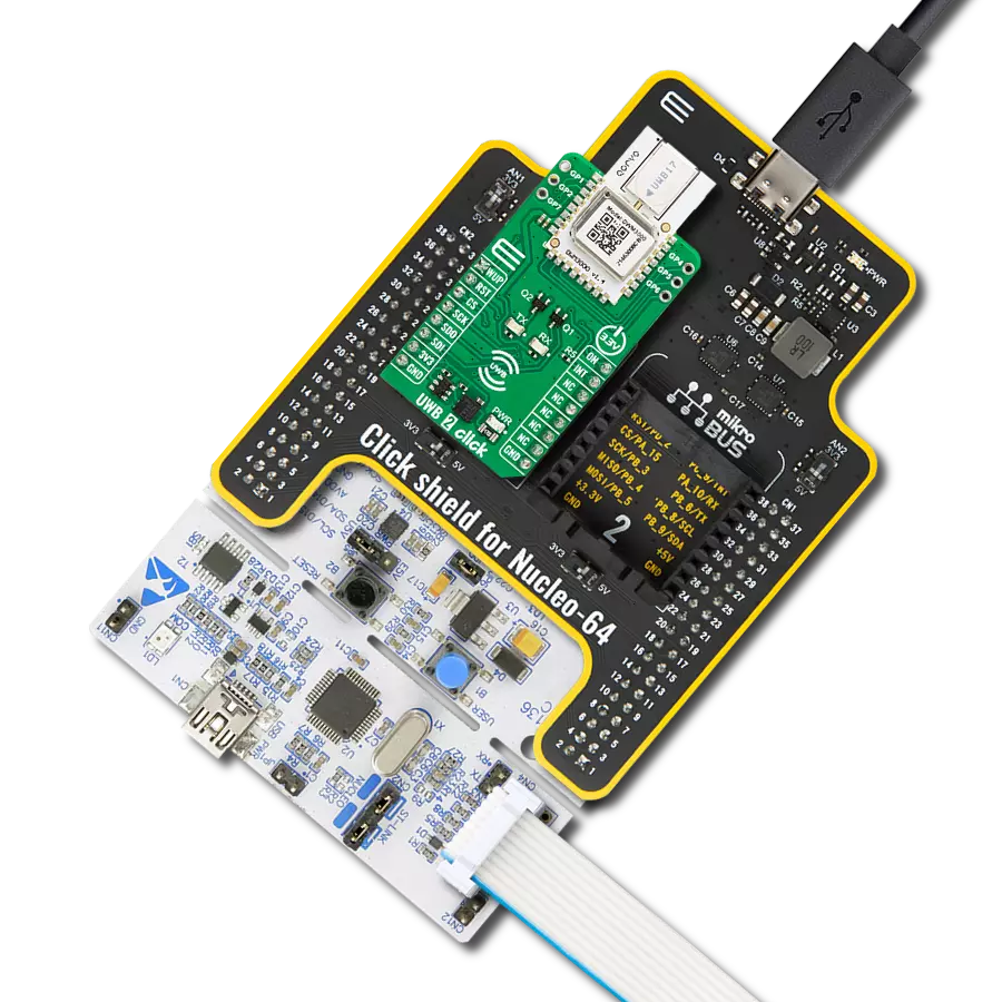
UWB 2 Click
开发板
Nucleo 32 with STM32F031K6 MCU
编译器
NECTO Studio
微控制器单元
STM32F031K6
我们的UWB收发器重新定义了实时定位系统(RTLS)和无线传感器网络(WSN)的格局,通过先进的双向测距和到达时间差(TDoA)方案提供动态且可靠的位置感知。
A
A
硬件概览
它是如何工作的?
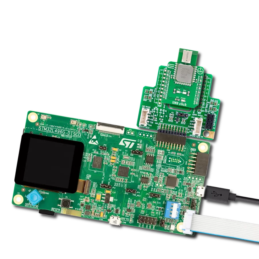
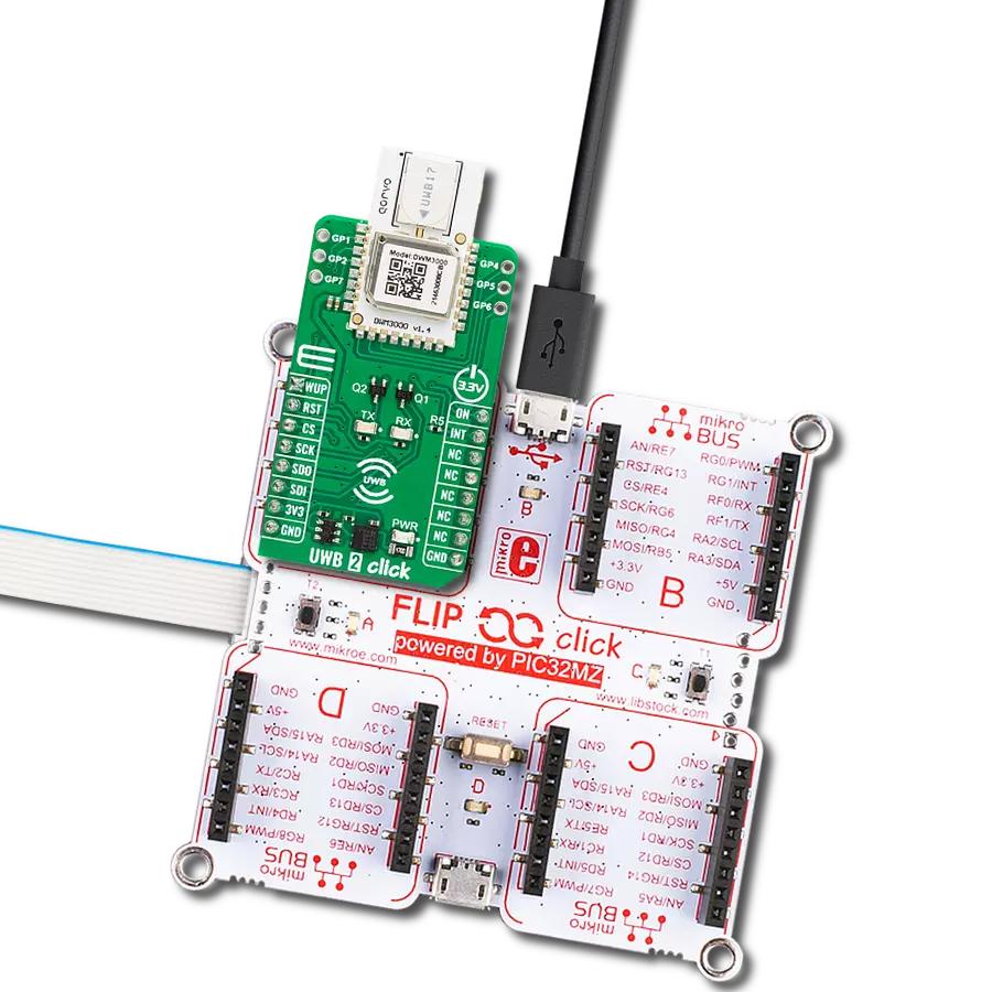
UWB 2 Click 基于Qorvo的DWM3000,这是一款IEEE 802.15-z UWB收发器模块。DWM3000模块基于Qorvo DW3110 IC,集成了天线、射频电路、功率管理和时钟电路。它可用于双向测距或到达时间差(TDoA)定位系统,实现精度达10厘米的资产定位,支持850Kbps至6.8Mbps的数据速率。该模块具有可编程的发射器输出功率、低功耗,并集成了MAC支持功能。对于高数据吞吐量应用,最大数据包长度为1023字节。DWM3000模块具有始终
开启(AON)内存,在片上电压调节器禁用时,可以在最低工作状态下保留DWM3000的配置数据。数据上传和下载是自动化的,AON内存是可配置的。您可以通过软件读取片上电压及其温度。除了AON内存,128x32位一次性可编程(OTP)内存还存储每个芯片的校准信息。模块有六个用户可编程的GPIO,引脚分布在DWM3000模块的两侧。两个蓝色LED,RX和TX,用于视觉呈现数据传输。UWB 2 Click 使用标准的4线SPI串行接口与主机
MCU通信。DWM3000模块可以通过RST引脚复位,通过WUP引脚唤醒。外部设备使能ON引脚可以用于控制外部DC-DC转换器或DW3110 IC的其他电路。可以配置几个中断事件来驱动INT中断引脚。此Click板™只能在3.3V逻辑电压电平下运行。使用不同逻辑电平的MCU之前,板子必须进行适当的逻辑电压电平转换。此外,该板还配备了包含功能和示例代码的库,可用作进一步开发的参考。

功能概述
开发板
Nucleo 32开发板搭载STM32F031K6 MCU,提供了一种经济且灵活的平台,适用于使用32引脚封装的STM32微控制器进行实验。该开发板具有Arduino™ Nano连接性,便于通过专用扩展板进行功能扩展,并且支持mbed,使其能够无缝集成在线资源。板载集成
ST-LINK/V2-1调试器/编程器,支持通过USB重新枚举,提供三种接口:虚拟串口(Virtual Com port)、大容量存储和调试端口。该开发板的电源供应灵活,可通过USB VBUS或外部电源供电。此外,还配备了三个LED指示灯(LD1用于USB通信,LD2用于电源
指示,LD3为用户可控LED)和一个复位按钮。STM32 Nucleo-32开发板支持多种集成开发环境(IDEs),如IAR™、Keil®和基于GCC的IDE(如AC6 SW4STM32),使其成为开发人员的多功能工具。

微控制器概述
MCU卡片 / MCU

建筑
ARM Cortex-M0
MCU 内存 (KB)
32
硅供应商
STMicroelectronics
引脚数
32
RAM (字节)
4096
你完善了我!
配件
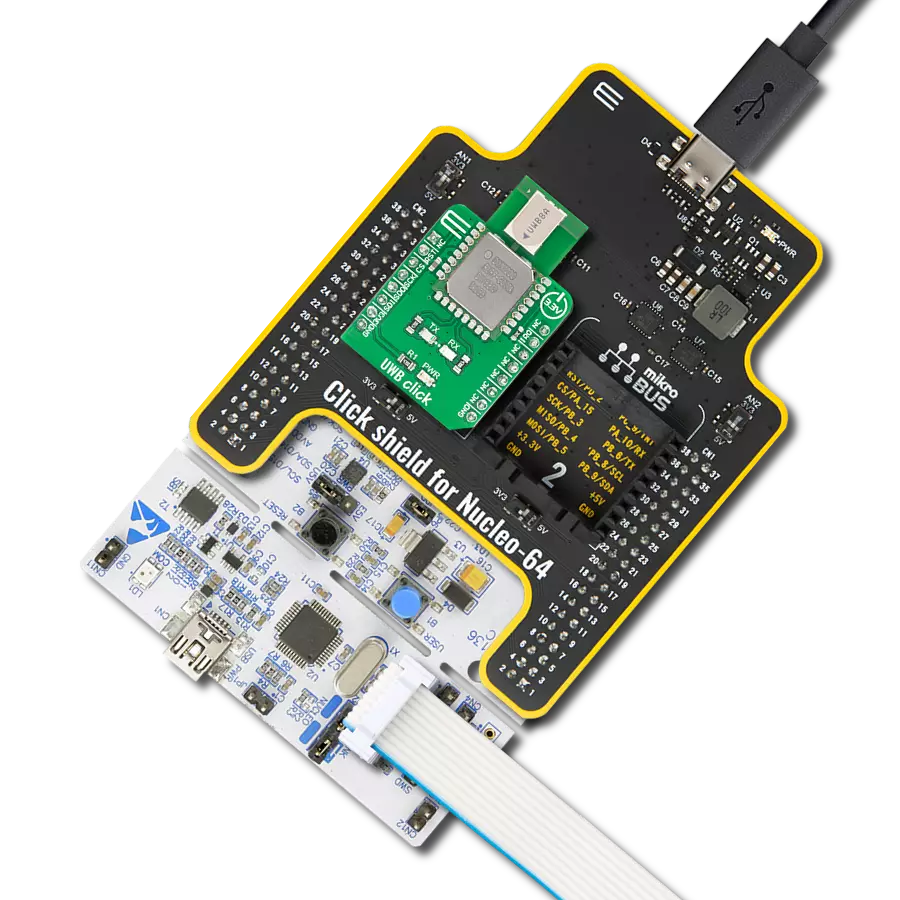
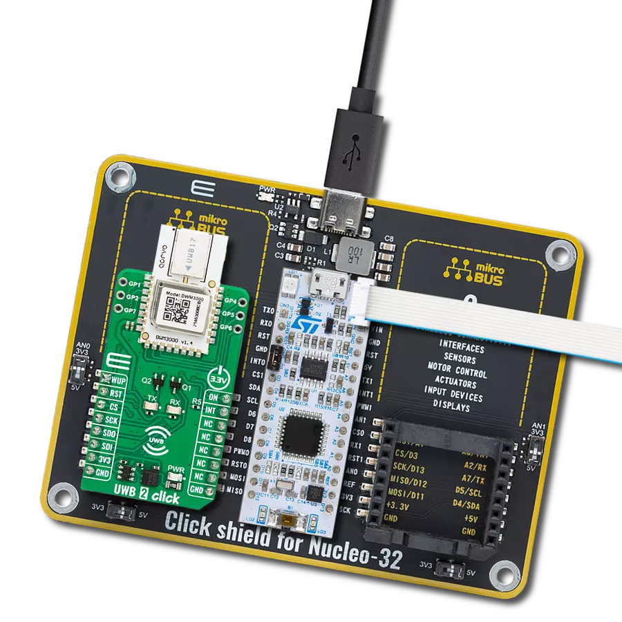
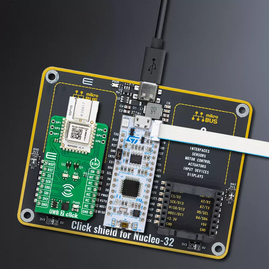
Click Shield for Nucleo-32是扩展您的开发板功能的理想选择,专为STM32 Nucleo-32引脚布局设计。Click Shield for Nucleo-32提供了两个mikroBUS™插座,可以添加来自我们不断增长的Click板™系列中的任何功能。从传感器和WiFi收发器到电机控制和音频放大器,我们应有尽有。Click Shield for Nucleo-32与STM32 Nucleo-32开发板兼容,为用户提供了一种经济且灵活的方式,使用任何STM32微控制器快速创建原型,并尝试各种性能、功耗和功能的组合。STM32 Nucleo-32开发板无需任何独立的探针,因为它集成了ST-LINK/V2-1调试器/编程器,并随附STM32全面的软件HAL库和各种打包的软件示例。这个开发平台为用户提供了一种简便且通用的方式,将STM32 Nucleo-32兼容开发板与他们喜欢的Click板™结合,应用于即将开展的项目中。

使用的MCU引脚
mikroBUS™映射器
“仔细看看!”
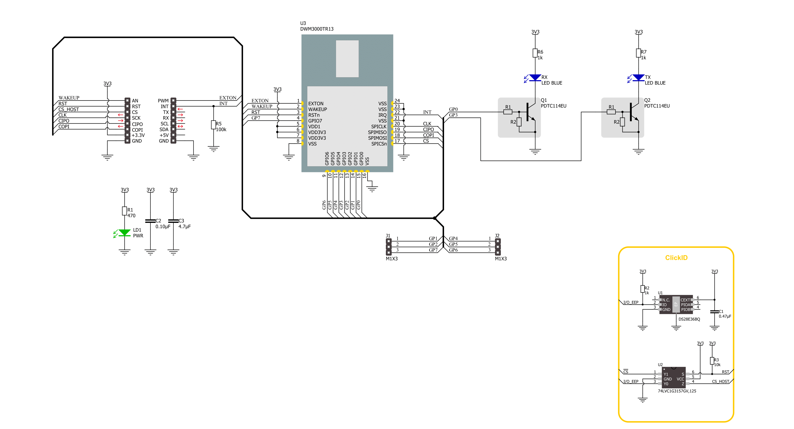
Click board™ 原理图
一步一步来
项目组装

从选择您的开发板和Click板™开始。以Nucleo 32 with STM32F031K6 MCU作为您的开发板开始。


软件支持
库描述
该库包含 UWB 2 Click 驱动程序的 API。
关键功能:
uwb2_read_reg_32bit- 此函数使用SPI串行接口从选定的寄存器读取32位数据。uwb2_send_message- 此函数将所需数量的数据字节写入TX缓冲区,设置TX消息大小,开始传输并等待TX帧发送事件。uwb2_read_message- 此函数激活接收,然后等待具有良好FCS/CRC的帧,从RX缓冲区读取最多len数量的数据字节,并根据实际读取的数据字节数量调整len参数。
开源
代码示例
完整的应用程序代码和一个现成的项目可以通过NECTO Studio包管理器直接安装到NECTO Studio。 应用程序代码也可以在MIKROE的GitHub账户中找到。
/*!
 * @file main.c
 * @brief UWB 2 Click example
 *
 * # Description
 * This example demonstrates the use of an UWB 2 Click board by showing
 * the communication between the two Click boards.
 *
 * The demo application is composed of two sections :
 *
 * ## Application Init
 * Initializes the driver, performs the Click default configuration, then reads
 * and displays the device ID number.
 *
 * ## Application Task
 * Depending on the selected application mode, it reads all the received data or
 * sends the desired text message with the message counter once per second.
 *
 * @author Stefan Filipovic
 *
 */

#include "board.h"
#include "log.h"
#include "uwb2.h"

// Comment out the line below in order to switch the application mode to receiver
#define DEMO_APP_TRANSMITTER

// Text message to send in the transmitter application mode
#define DEMO_TEXT_MESSAGE           "MIKROE - UWB 2 Click board\0"

static uwb2_t uwb2;
static log_t logger;

void application_init ( void )
{
    log_cfg_t log_cfg;  /**< Logger config object. */
    uwb2_cfg_t uwb2_cfg;  /**< Click config object. */

    /**
     * Logger initialization.
     * Default baud rate: 115200
     * Default log level: LOG_LEVEL_DEBUG
     * @note If USB_UART_RX and USB_UART_TX
     * are defined as HAL_PIN_NC, you will
     * need to define them manually for log to work.
     * See @b LOG_MAP_USB_UART macro definition for detailed explanation.
     */
    LOG_MAP_USB_UART( log_cfg );
    log_init( &logger, &log_cfg );
    log_info( &logger, " Application Init " );

    // Click initialization.
    uwb2_cfg_setup( &uwb2_cfg );
    UWB2_MAP_MIKROBUS( uwb2_cfg, MIKROBUS_1 );
    if ( SPI_MASTER_ERROR == uwb2_init( &uwb2, &uwb2_cfg ) )
    {
        log_error( &logger, " Communication init." );
        for ( ; ; );
    }

    if ( UWB2_ERROR == uwb2_default_cfg ( &uwb2 ) )
    {
        log_error( &logger, " Default configuration." );
        for ( ; ; );
    }

    uint32_t dev_id = 0;
    if ( UWB2_OK == uwb2_read_reg_32bit ( &uwb2, UWB2_REG_DEV_ID, &dev_id ) )
    {
        log_printf ( &logger, " Device ID: 0x%.8LX\r\n", dev_id );
    }

#ifdef DEMO_APP_TRANSMITTER
    log_printf( &logger, " Application Mode: Transmitter\r\n" );
#else
    log_printf( &logger, " Application Mode: Receiver\r\n" );
#endif

    log_info( &logger, " Application Task " );
}

void application_task ( void )
{
#ifdef DEMO_APP_TRANSMITTER
    static uint8_t tx_msg_cnt = 0;
    uint8_t tx_buffer[ 128 ] = { 0 };
    uint16_t tx_msg_size = 0;
    tx_buffer[ 0 ] = tx_msg_cnt; // Message number.
    strcpy ( &tx_buffer[ 1 ], DEMO_TEXT_MESSAGE );
    tx_msg_size = strlen ( DEMO_TEXT_MESSAGE ) + 2; // Message size + null-terminated + tx_msg_cnt
    if ( UWB2_OK == uwb2_send_message ( &uwb2, tx_buffer, tx_msg_size ) )
    {
        log_printf ( &logger, " Message sent #%u\r\n\n", tx_buffer[ 0 ] );
        tx_msg_cnt++; // Increment message number (modulo 256).
    }
    Delay_ms ( 1000 );
#else
    uint8_t rx_buffer[ 128 ] = { 0 };
    uint16_t rx_msg_size = sizeof ( rx_buffer );
    if ( UWB2_OK == uwb2_read_message ( &uwb2, rx_buffer, &rx_msg_size ) )
    {
        log_printf ( &logger, " Message received #%u: %s\r\n\n",
                     ( uint16_t ) rx_buffer[ 0 ], &rx_buffer[ 1 ] );
    }
#endif
}

int main ( void )
{
    /* Do not remove this line or clock might not be set correctly. */
    #ifdef PREINIT_SUPPORTED
    preinit();
    #endif

    application_init( );

    for ( ; ; )
    {
        application_task( );
    }

    return 0;
}

// ------------------------------------------------------------------------ END
额外支持
资源
类别:超宽带