通过使用AD9833和STM32F031K6释放波形交响乐
正弦/三角/方波生成器

已发布 10月 01, 2024
点击板
Waveform Click
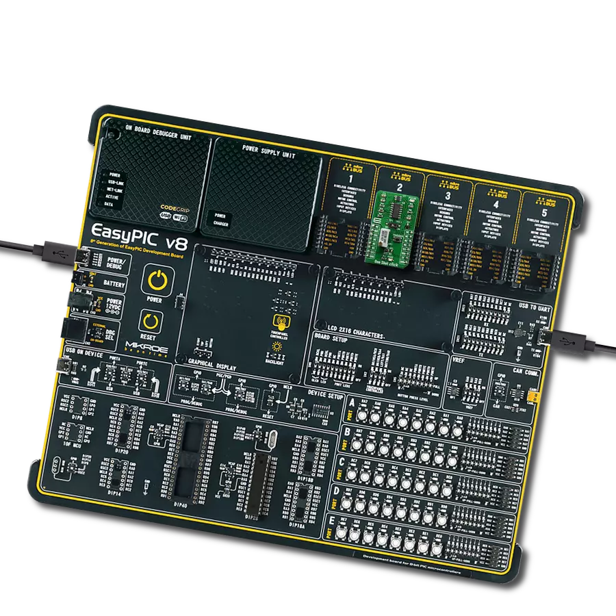
开发板
Nucleo 32 with STM32F031K6 MCU
编译器
NECTO Studio
微控制器单元
STM32F031K6
探索这款全面的波形发生器,为您的解决方案添加无缝的信号生成功能。
A
A
硬件概览
它是如何工作的?
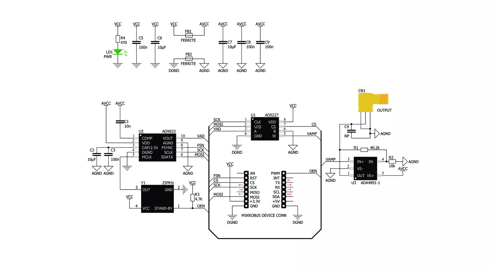
Waveform Click基于Analog Devices的AD9833,这是一款低功耗、可编程的波形发生器。Analog Devices在高质量数字信号处理(DSP)解决方案市场上享有盛誉。AD9833 IC基于直接数字合成(DDS),在其输出端生成具有可编程频率和可选波形的波形。AD9833和同一公司的数字电位计IC AD5227通过SPI接口控制,允许频率和振幅快速变化,无需额外的延迟。DDS通过利用信号相位线性变化的事实来生成模拟波形。对于简单的周期函数(如正弦函数),相位在线性变化的范围为0到2π。这允许构建数控振荡器(NCO)块,其输出的数值随时间线性变化,在0到2^28 - 1之间(因为AD9833 IC具有28位相位累加器)。NCO块的连续变化输出用作查找表(LUT)的索引,LUT包含输出波形的振幅。NCO输出变化越快,输出信号频率越高,这是DDS的基础。与其他类型的合成(例如PLL)相比,
DDS的主要优势在于其简单的方法。频率可以以小步长(取决于时钟发生器)变化,而最大频率可以轻松达到GHz。除了NCO和LUT,AD9833还包含其他必要的模块来在输出端生成波形。它还具有10位DAC,将数字值转换为输出端的模拟电压。由于ADC只有10位宽,LUT不需要太多元素。ADC的分辨率是瓶颈,因此LUT数据需要稍高的分辨率。这进一步降低了复杂性和成本。AD9833可以完全避免使用LUT,生成方波(仅使用DAC的MSB),其频率可以进一步倍增,生成三角波(通过将NCO直接重定向到DAC而不是通过LUT扫描)。AD9833的工作模式可以通过SPI接口上的配置寄存器进行设置。有关AD9833 IC的更多详细信息,请参阅AD9833的数据手册。然而,兼容mikroSDK的库包含简化与AD9833 IC一起使用的函数。AD9833的输出被路由到AD5227数字电位计,用于设置输出信号的
振幅。此电位计用于在0V和3.3V之间缩小振幅。它通过SPI接口控制。使用电位计是因为AD9833 IC不提供调节输出信号振幅的方法。Waveform Click使用25MHz时钟发生器,允许频率以0.1Hz的步长变化。时钟的高速允许生成非常高的频率,使得此Click板™可以生成频率高达5MHz的非常干净的正弦波和频率高达12MHz的方波。集成的时钟发生器提供一个STAND-BY引脚,用于打开或关闭时钟。如果此引脚具有高电平逻辑状态,则时钟发生器将生成25MHz时钟信号。此引脚通过上拉电阻连接到VCC,因此默认情况下启用25MHz时钟发生器。Click板™的输出信号由ADA4891-1低噪声运算放大器缓冲,提供恒定阻抗和对整个电路的有限保护。它可以通过SMA连接器获得,允许使用屏蔽同轴电缆。


功能概述
开发板
Nucleo 32开发板搭载STM32F031K6 MCU,提供了一种经济且灵活的平台,适用于使用32引脚封装的STM32微控制器进行实验。该开发板具有Arduino™ Nano连接性,便于通过专用扩展板进行功能扩展,并且支持mbed,使其能够无缝集成在线资源。板载集成
ST-LINK/V2-1调试器/编程器,支持通过USB重新枚举,提供三种接口:虚拟串口(Virtual Com port)、大容量存储和调试端口。该开发板的电源供应灵活,可通过USB VBUS或外部电源供电。此外,还配备了三个LED指示灯(LD1用于USB通信,LD2用于电源
指示,LD3为用户可控LED)和一个复位按钮。STM32 Nucleo-32开发板支持多种集成开发环境(IDEs),如IAR™、Keil®和基于GCC的IDE(如AC6 SW4STM32),使其成为开发人员的多功能工具。

微控制器概述
MCU卡片 / MCU

建筑
ARM Cortex-M0
MCU 内存 (KB)
32
硅供应商
STMicroelectronics
引脚数
32
RAM (字节)
4096
你完善了我!
配件
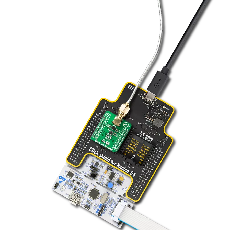
Click Shield for Nucleo-32是扩展您的开发板功能的理想选择,专为STM32 Nucleo-32引脚布局设计。Click Shield for Nucleo-32提供了两个mikroBUS™插座,可以添加来自我们不断增长的Click板™系列中的任何功能。从传感器和WiFi收发器到电机控制和音频放大器,我们应有尽有。Click Shield for Nucleo-32与STM32 Nucleo-32开发板兼容,为用户提供了一种经济且灵活的方式,使用任何STM32微控制器快速创建原型,并尝试各种性能、功耗和功能的组合。STM32 Nucleo-32开发板无需任何独立的探针,因为它集成了ST-LINK/V2-1调试器/编程器,并随附STM32全面的软件HAL库和各种打包的软件示例。这个开发平台为用户提供了一种简便且通用的方式,将STM32 Nucleo-32兼容开发板与他们喜欢的Click板™结合,应用于即将开展的项目中。

使用的MCU引脚
mikroBUS™映射器
“仔细看看!”
Click board™ 原理图
一步一步来
项目组装

从选择您的开发板和Click板™开始。以Nucleo 32 with STM32F031K6 MCU作为您的开发板开始。


实时跟踪您的结果
应用程序输出
1. 应用程序输出 - 在调试模式下,“应用程序输出”窗口支持实时数据监控,直接提供执行结果的可视化。请按照提供的教程正确配置环境,以确保数据正确显示。

2. UART 终端 - 使用UART Terminal通过USB to UART converter监视数据传输,实现Click board™与开发系统之间的直接通信。请根据项目需求配置波特率和其他串行设置,以确保正常运行。有关分步设置说明,请参考提供的教程。

3. Plot 输出 - Plot功能提供了一种强大的方式来可视化实时传感器数据,使趋势分析、调试和多个数据点的对比变得更加直观。要正确设置,请按照提供的教程,其中包含使用Plot功能显示Click board™读数的分步示例。在代码中使用Plot功能时,请使用以下函数:plot(insert_graph_name, variable_name);。这是一个通用格式,用户需要将“insert_graph_name”替换为实际图表名称,并将“variable_name”替换为要显示的参数。

软件支持
库描述
该库包含Waveform Click驱动程序的 API。
关键功能:
waveform_sine_output- 正弦波输出功能waveform_triangle_output- 三角波输出功能waveform_square_output- 方波输出功能
开源
代码示例
完整的应用程序代码和一个现成的项目可以通过NECTO Studio包管理器直接安装到NECTO Studio。 应用程序代码也可以在MIKROE的GitHub账户中找到。
/*!
 * \file
 * \brief Waveform Click example
 *
 * # Description
 * This example demonstrates the use of Waveform Click board.
 *
 * The application is composed of two sections :
 *
 * ## Application Init
 * Initializes the communication interface and configures the Click board.
 *
 * ## Application Task
 * Predefined commands are inputed from the serial port.
 * Changes the signal frequency, waveform or amplitude depending on the receiver command.
 *
 * \author MikroE Team
 *
 */

#include "board.h"
#include "log.h"
#include "waveform.h"

static waveform_t waveform;
static log_t logger;

static uint32_t frequency = 200000;
static uint32_t frequency_step = 10000;

/**
 * @brief Waveform display commands function.
 * @details This function displays the list of supported commands on the USB UART.
 * @return None.
 * @note None.
 */
void waveform_display_commands ( void );

/**
 * @brief Waveform parse command function.
 * @details This function checks if the input command is supported and executes it.
 * @param[in] command : Command input, for more details refer to @b waveform_display_commands function.
 * @return None.
 * @note None.
 */
void waveform_parse_command ( uint8_t command );

void application_init ( void )
{
    log_cfg_t log_cfg;
    waveform_cfg_t waveform_cfg;

    /**
     * Logger initialization.
     * Default baud rate: 115200
     * Default log level: LOG_LEVEL_DEBUG
     * @note If USB_UART_RX and USB_UART_TX
     * are defined as HAL_PIN_NC, you will
     * need to define them manually for log to work.
     * See @b LOG_MAP_USB_UART macro definition for detailed explanation.
     */
    LOG_MAP_USB_UART( log_cfg );
    log_init( &logger, &log_cfg );
    log_info( &logger, " Application Init " );

    // Click initialization.
    waveform_cfg_setup( &waveform_cfg );
    WAVEFORM_MAP_MIKROBUS( waveform_cfg, MIKROBUS_1 );
    if ( SPI_MASTER_ERROR == waveform_init( &waveform, &waveform_cfg ) )
    {
        log_error( &logger, " Communication init." );
        for ( ; ; );
    }

    waveform_sine_output( &waveform, frequency );
    log_printf( &logger, "Sine wave output set with approx. frequency: %lu Hz\r\n", frequency );
    waveform_display_commands ( );
    log_info( &logger, " Application Task " );
}

void application_task ( void )
{
    uint8_t command = 0;
    if ( 1 == log_read ( &logger, &command, 1 ) )
    {
        waveform_parse_command ( command );
    }
}

int main ( void )
{
    /* Do not remove this line or clock might not be set correctly. */
    #ifdef PREINIT_SUPPORTED
    preinit();
    #endif

    application_init( );

    for ( ; ; )
    {
        application_task( );
    }

    return 0;
}

void waveform_display_commands ( void )
{
    log_printf( &logger, "-------------------------------------------\r\n" );
    log_info( &logger, "- UART commands list -\r\n" );
    log_printf( &logger, "'+' - Increase amplitude.\r\n" );
    log_printf( &logger, "'-' - Decrease amplitude.\r\n" );
    log_printf( &logger, "'S' - Select sine wave output and increase frequency.\r\n" );
    log_printf( &logger, "'s' - Select sine wave output and decrease frequency.\r\n" );
    log_printf( &logger, "'T' - Select triangle wave output and increase frequency.\r\n" );
    log_printf( &logger, "'t' - Select triangle wave output and decrease frequency.\r\n" );
    log_printf( &logger, "'Q' - Select square wave output and increase frequency.\r\n" );
    log_printf( &logger, "'q' - Select square wave output and decrease frequency.\r\n" );
    log_printf( &logger, "'L' or 'l' - Display commands list.\r\n" );
    log_printf( &logger, "-------------------------------------------\r\n" );
}

void waveform_parse_command ( uint8_t command )
{
    switch ( command )
    {
        case '+':
        {
            log_printf( &logger, "Increasing amplitude of the current wave.\r\n" );
            waveform_digipot_inc ( &waveform );
            break;
        }
        case '-':
        {
            log_printf( &logger, "Decreasing amplitude of the current wave.\r\n" );
            waveform_digipot_dec ( &waveform );
            break;
        }
        case 'S':
        {
            log_printf( &logger, "Increasing frequency of the sine wave.\r\n" );
            frequency += frequency_step;
            waveform_sine_output( &waveform, frequency );
            log_printf( &logger, "Approx. frequency: %lu Hz\r\n", frequency );
            break;
        }
        case 's':
        {
            log_printf( &logger, "Decreasing frequency of the sine wave.\r\n" );
            if ( frequency < frequency_step )
            {
                frequency = 0;
            }
            else
            {
                frequency -= frequency_step;
            }
            waveform_sine_output( &waveform, frequency );
            log_printf( &logger, "Approx. frequency: %lu Hz\r\n", frequency );
            break;
        }
        case 'T':
        {
            log_printf( &logger, "Increasing frequency of the triangle wave.\r\n" );
            frequency += frequency_step;
            waveform_triangle_output( &waveform, frequency );
            log_printf( &logger, "Approx. frequency: %lu Hz\r\n", frequency );
            break;
        }
        case 't':
        {
            log_printf( &logger, "Decreasing frequency of the triangle wave.\r\n" );
            if ( frequency < frequency_step )
            {
                frequency = 0;
            }
            else
            {
                frequency -= frequency_step;
            }
            waveform_triangle_output( &waveform, frequency );
            log_printf( &logger, "Approx. frequency: %lu Hz\r\n", frequency );
            break;
        }
        case 'Q':
        {
            log_printf( &logger, "Increasing frequency of the square wave.\r\n" );
            frequency += frequency_step;
            waveform_square_output( &waveform, frequency );
            log_printf( &logger, "Approx. frequency: %lu Hz\r\n", frequency );
            break;
        }
        case 'q':
        {
            log_printf( &logger, "Decreasing frequency of the square wave.\r\n" );
            if ( frequency < frequency_step )
            {
                frequency = 0;
            }
            else
            {
                frequency -= frequency_step;
            }
            waveform_square_output( &waveform, frequency );
            log_printf( &logger, "Approx. frequency: %lu Hz\r\n", frequency );
            break;
        }
        case 'L': case 'l':
        {
            waveform_display_commands ( );
            break;
        }
        default :
        {
            log_error( &logger, "Wrong command." );
            break;
        }
    }
}

// ------------------------------------------------------------------------ END