使用PCA9518和STM32G474RE将I2C总线分成多个子分支以解决地址冲突问题
I2C多路复用

已发布 11月 08, 2024
点击板
I2C MUX 6 Click
开发板
Nucleo 64 with STM32G474RE MCU
编译器
NECTO Studio
微控制器单元
STM32G474RE
用于 I2C 和 SMBus 应用的可扩展缓冲区,提供四个双向数据传输通道。
A
A
硬件概览
它是如何工作的?
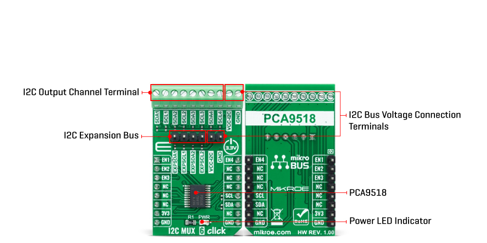
I2C MUX 6 Click 基于德州仪器的 PCA9518,这是一款可扩展的四通道双向缓冲器,可通过 I2C 串行接口控制。主要的 SCL/SDA 信号对被引导到四个通道,其中只能选择一个 SCL/SDA 通道,由连接到 mikroBUS™ 插座的 AN、RST、CS 和 PWM 引脚的四个 Enable 引脚的状态决定。PCA9518 通过将 I2C 数据(SDA)和时钟(SCL)线分离和缓冲到多个 400pF I2C 通道组中,克服了总线最大电容的限制。PCA9518 具有多个多方向开漏缓冲器,旨在支持 I2C 总线的标准低电平竞争仲裁。除了
仲裁期间,PCA9518 像一对非反向开漏缓冲器,一个用于 SDA,一个用于 SCL。它可以通过板载标记为 EXP 的引脚上的 4 线集线器间扩展总线与其他 PCA9518 集线器通信,即通过缓冲数据(SDA)和时钟(SCL)线扩展 I2C 总线,允许几乎无限数量的 400pF 总线。PCA9518 使用支持标准模式(100 kHz)和快速模式(400 kHz)操作的标准 I2C 接口与 MCU 通信。如前所述,每个 Enable 引脚,ENx,控制其相关联的 SDAx 和 SCLx 通道。当 ENx 引脚处于低逻辑状态时,它通过阻止 SDAx 和 SCLx 的输入并禁
用这些线上的输出驱动器,使其对应的 SDAx 和 SCLx 线与系统隔离。为了防止系统故障,ENx 的状态更改只能在全局总线和本地端口都处于空闲状态时进行。此 Click board™ 设计用于 3.3V 操作。它还具有板载终端,标记为 VCC-I2C,用于为 PCA9518 的 I2C 线提供 3.3V 或 5V 的逻辑电压,这些线是 5V 容忍的。然而,在使用不同逻辑电平的 MCU 之前,板必须执行适当的逻辑电压电平转换。该 Click board™ 配备了包含函数和示例代码的库,可作为进一步开发的参考。
功能概述
开发板
Nucleo-64 搭载 STM32G474R MCU 提供了一种经济高效且灵活的平台,供开发者探索新想法并原型设计他们的项目。该板利用 STM32 微控制器的多功能性,使用户能够为他们的项目选择最佳的性能与功耗平衡。它配备了 LQFP64 封装的 STM32 微控制器,并包含了如用户 LED(同时作为 ARDUINO® 信号)、用户和复位按钮,以及 32.768kHz 晶体振荡器用于精确的计时操作等基本组件。Nucleo-64 板设计考虑到扩展性和灵活性,它特有的 ARDUINO® Uno
V3 扩展连接器和 ST morpho 扩展引脚头,提供了对 STM32 I/O 的完全访问,以实现全面的项目整合。电源供应选项灵活,支持 ST-LINK USB VBUS 或外部电源,确保在各种开发环境中的适应性。该板还配备了一个具有 USB 重枚举功能的板载 ST-LINK 调试器/编程器,简化了编程和调试过程。此外,该板设计旨在简化高级开发,它的外部 SMPS 为 Vcore 逻辑供电提供高效支持,支持 USB 设备全速或 USB SNK/UFP 全速,并内置加密功能,提升了项目的功效
和安全性。通过外部 SMPS 实验的专用连接器、 用于 ST-LINK 的 USB 连接器以及 MIPI® 调试连接器,提供了更多的硬件接口和实验可能性。开发者将通过 STM32Cube MCU Package 提供的全面免费软件库和示例得到广泛支持。这些,加上与多种集成开发环境(IDE)的兼容性,包括 IAR Embedded Workbench®、MDK-ARM 和 STM32CubeIDE,确保了流畅且高效的开发体验,使用户能够充分利用 Nucleo-64 板在他们的项目中的能力。

微控制器概述
MCU卡片 / MCU

建筑
ARM Cortex-M4
MCU 内存 (KB)
512
硅供应商
STMicroelectronics
引脚数
64
RAM (字节)
128k
你完善了我!
配件
Click Shield for Nucleo-64 配备了两个专有的 mikroBUS™ 插座,使得所有的 Click board™ 设备都可以轻松地与 STM32 Nucleo-64 开发板连接。这样,Mikroe 允许其用户从不断增长的 Click boards™ 范围中添加任何功能,如 WiFi、GSM、GPS、蓝牙、ZigBee、环境传感器、LED、语音识别、电机控制、运动传感器等。您可以使用超过 1537 个 Click boards™,这些 Click boards™ 可以堆叠和集成。STM32 Nucleo-64 开发板基于 64 引脚封装的微控制器,采用 32 位 MCU,配备 ARM Cortex M4 处理器,运行速度为 84MHz,具有 512Kb Flash 和 96KB SRAM,分为两个区域,顶部区域代表 ST-Link/V2 调试器和编程器,而底部区域是一个实际的开发板。通过 USB 连接方便地控制和供电这些板子,以便直接对 Nucleo-64 开发板进行编程和高效调试,其中还需要额外的 USB 线连接到板子上的 USB 迷你接口。大多数 STM32 微控制器引脚都连接到了板子左右边缘的 IO 引脚上,然后连接到两个现有的 mikroBUS™ 插座上。该 Click Shield 还有几个开关,用于选择 mikroBUS™ 插座上模拟信号的逻辑电平和 mikroBUS™ 插座本身的逻辑电压电平。此外,用户还可以通过现有的双向电平转换器,使用任何 Click board™,无论 Click board™ 是否在 3.3V 或 5V 逻辑电压电平下运行。一旦将 STM32 Nucleo-64 开发板与我们的 Click Shield for Nucleo-64 连接,您就可以访问数百个工作于 3.3V 或 5V 逻辑电压电平的 Click boards™。

使用的MCU引脚
mikroBUS™映射器
“仔细看看!”
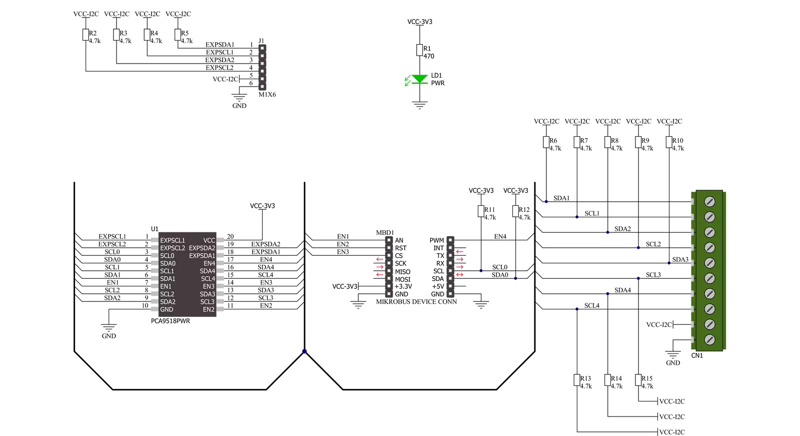
Click board™ 原理图
一步一步来
项目组装
从选择您的开发板和Click板™开始。以Nucleo 64 with STM32G474RE MCU作为您的开发板开始。


实时跟踪您的结果
应用程序输出
1. 应用程序输出 - 在调试模式下,“应用程序输出”窗口支持实时数据监控,直接提供执行结果的可视化。请按照提供的教程正确配置环境,以确保数据正确显示。

2. UART 终端 - 使用UART Terminal通过USB to UART converter监视数据传输,实现Click board™与开发系统之间的直接通信。请根据项目需求配置波特率和其他串行设置,以确保正常运行。有关分步设置说明,请参考提供的教程。

3. Plot 输出 - Plot功能提供了一种强大的方式来可视化实时传感器数据,使趋势分析、调试和多个数据点的对比变得更加直观。要正确设置,请按照提供的教程,其中包含使用Plot功能显示Click board™读数的分步示例。在代码中使用Plot功能时,请使用以下函数:plot(insert_graph_name, variable_name);。这是一个通用格式,用户需要将“insert_graph_name”替换为实际图表名称,并将“variable_name”替换为要显示的参数。

软件支持
库描述
该库包含 I2C MUX 6 Click 驱动程序的 API。
关键功能:
i2cmux6_set_channel- 此函数设置所需通道为活动状态并配置其从地址。i2cmux6_generic_write- 此函数使用 I2C 串行接口从选定的寄存器开始写入所需数量的数据字节。i2cmux6_generic_read- 此函数使用 I2C 串行接口从选定的寄存器开始读取所需数量的数据字节。
开源
代码示例
完整的应用程序代码和一个现成的项目可以通过NECTO Studio包管理器直接安装到NECTO Studio。 应用程序代码也可以在MIKROE的GitHub账户中找到。
/*!
 * @file main.c
 * @brief I2CMUX6 Click example
 *
 * # Description
 * This example demonstrates the use of I2C MUX 6 click board by reading the
 * device ID of a 6DOF IMU 11 and Compass 3 click boards connected to
 * the channels 1 and 4 respectfully.
 *
 * The demo application is composed of two sections :
 *
 * ## Application Init
 * Initializes the driver and logger.
 *
 * ## Application Task
 * Reads the device ID of the connected click boards.
 * Channel 1 : 6DOF IMU 11 click [slave address: 0x0E; reg: 0x00; id: 0x2D],
 * Channel 4 : Compass 3 click   [slave address: 0x30; reg: 0x2F; id: 0x0C].
 * All data is being logged on the USB UART where you can check the device ID.
 *
 * @note
 * Make sure to provide 3v3 power supply on VCC-I2C pin.
 *
 * @author Stefan Filipovic
 *
 */

#include "board.h"
#include "log.h"
#include "i2cmux6.h"

#define DEVICE0_NAME                "6DOF IMU 11 click"
#define DEVICE0_POSITION            I2CMUX6_CHANNEL_1
#define DEVICE0_SLAVE_ADDRESS       0x0E
#define DEVICE0_REG_ID              0x00
#define DEVICE0_ID                  0x2D

#define DEVICE1_NAME                "Compass 3 click"
#define DEVICE1_POSITION            I2CMUX6_CHANNEL_4
#define DEVICE1_SLAVE_ADDRESS       0x30
#define DEVICE1_REG_ID              0x2F
#define DEVICE1_ID                  0x0C

static i2cmux6_t i2cmux6;
static log_t logger;

void application_init ( void )
{
    log_cfg_t log_cfg;  /**< Logger config object. */
    i2cmux6_cfg_t i2cmux6_cfg;  /**< Click config object. */

    /**
     * Logger initialization.
     * Default baud rate: 115200
     * Default log level: LOG_LEVEL_DEBUG
     * @note If USB_UART_RX and USB_UART_TX
     * are defined as HAL_PIN_NC, you will
     * need to define them manually for log to work.
     * See @b LOG_MAP_USB_UART macro definition for detailed explanation.
     */
    LOG_MAP_USB_UART( log_cfg );
    log_init( &logger, &log_cfg );
    log_info( &logger, " Application Init " );

    // Click initialization.
    i2cmux6_cfg_setup( &i2cmux6_cfg );
    I2CMUX6_MAP_MIKROBUS( i2cmux6_cfg, MIKROBUS_1 );
    if ( I2C_MASTER_ERROR == i2cmux6_init( &i2cmux6, &i2cmux6_cfg ) )
    {
        log_error( &logger, " Communication init." );
        for ( ; ; );
    }

    log_info( &logger, " Application Task " );
}

void application_task ( void )
{
    uint8_t device_id;
    if ( I2CMUX6_OK == i2cmux6_set_channel ( &i2cmux6, DEVICE0_POSITION, DEVICE0_SLAVE_ADDRESS ) )
    {
        log_printf( &logger, "\r\n Active Channel: - " );
        for ( uint8_t cnt = 0; cnt < 4; cnt++ )
        {
            if ( ( DEVICE0_POSITION ) & ( 1 << cnt ) )
            {
                log_printf( &logger, "%u - ", ( uint16_t ) ( cnt + 1 ) );
            }
        }
        if ( I2CMUX6_OK == i2cmux6_generic_read ( &i2cmux6, DEVICE0_REG_ID, &device_id, 1 ) )
        {
            log_printf( &logger, "\r\n %s - Device ID: 0x%.2X\r\n", ( char * ) DEVICE0_NAME, ( uint16_t ) device_id );
        }
        Delay_ms ( 1000 );
    }
    if ( I2CMUX6_OK == i2cmux6_set_channel ( &i2cmux6, DEVICE1_POSITION, DEVICE1_SLAVE_ADDRESS ) )
    {
        log_printf( &logger, "\r\n Active Channel: - " );
        for ( uint8_t cnt = 0; cnt < 4; cnt++ )
        {
            if ( ( DEVICE1_POSITION ) & ( 1 << cnt ) )
            {
                log_printf( &logger, "%u - ", ( uint16_t ) ( cnt + 1 ) );
            }
        }
        if ( I2CMUX6_OK == i2cmux6_generic_read ( &i2cmux6, DEVICE1_REG_ID, &device_id, 1 ) )
        {
            log_printf( &logger, "\r\n %s - Device ID: 0x%.2X\r\n", ( char * ) DEVICE1_NAME, ( uint16_t ) device_id );
        }
        Delay_ms ( 1000 );
    }
}

int main ( void )
{
    /* Do not remove this line or clock might not be set correctly. */
    #ifdef PREINIT_SUPPORTED
    preinit();
    #endif

    application_init( );

    for ( ; ; )
    {
        application_task( );
    }

    return 0;
}

// ------------------------------------------------------------------------ END


