Experience a revolution in temperature monitoring thanks to TSYS03 and MK64FN1M0VDC12
ThermoSense: Smart. Simple. Precise.

Published Nov 11, 2023
Click board™
Thermo 20 Click
Development board
Clicker 2 for Kinetis
Compiler
NECTO Studio
MCU
MK64FN1M0VDC12
Measuring heat with ease has never been simpler, thanks to our innovative temperature monitoring solution.
A
A
Hardware Overview
How does it work?
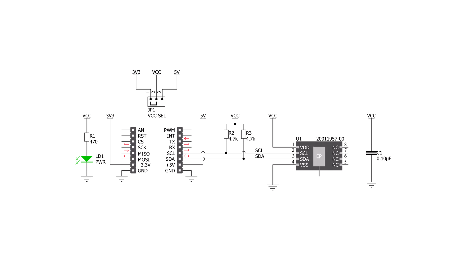
Thermo 20 Click is based on the TSYS03, an ultra-compact digital temperature sensor with precise digital output and low power consumption from TE Connectivity. The TSYS03 is factory-calibrated and provides accurate temperature measurements through several I2C configurable addresses. Operating from a supply voltage between 2.4V and 5.5V and drawing just 5µA Thermo 20 Click board™ is well suited for battery-powered and automotive applications. With an extended operating range from -40°C to +125°C, the TSYS03 provides digital temperature measurements that offer an accuracy of ±0.5°C when operating at ambient temperatures between 0°C and 60°C. The TSYS03 consists of a semiconductor
diode as a measuring element, which was integrated into an ASIC. The temperature is obtained from the voltage that drops across the diode and through an A/D converter with a 16-bit resolution. The output is obtained as a digital value via a configurable I2C interface. The TSYS03 impresses with its high accuracy, current consumption lower than 5 µA, and low self-heating of max. 0.1 °C. Thermo 20 Click communicates with MCU using the standard I2C 2-Wire interface with a maximum clock frequency of 1MHz. The standard I2C address is 0x40, but the sensor can also react to a second, alternative I2C address. It is possible to do one-time subsequent writing of an alternative static I2C address.
This leads to a wrong memory CRC, but the sensor is still functional. It is also possible to write an alternative I2C address to the sensor during operation. This address is temporary and is overwritten during a software reset or a hardware restart function. This Click board™ can operate with either 3.3V or 5V logic voltage levels selected via the VCC SEL jumper. This way, both 3.3V and 5V capable MCUs can use the communication lines properly. Also, this Click board™ comes equipped with a library containing easy-to-use functions and an example code that can be used as a reference for further development.

Features overview
Development board
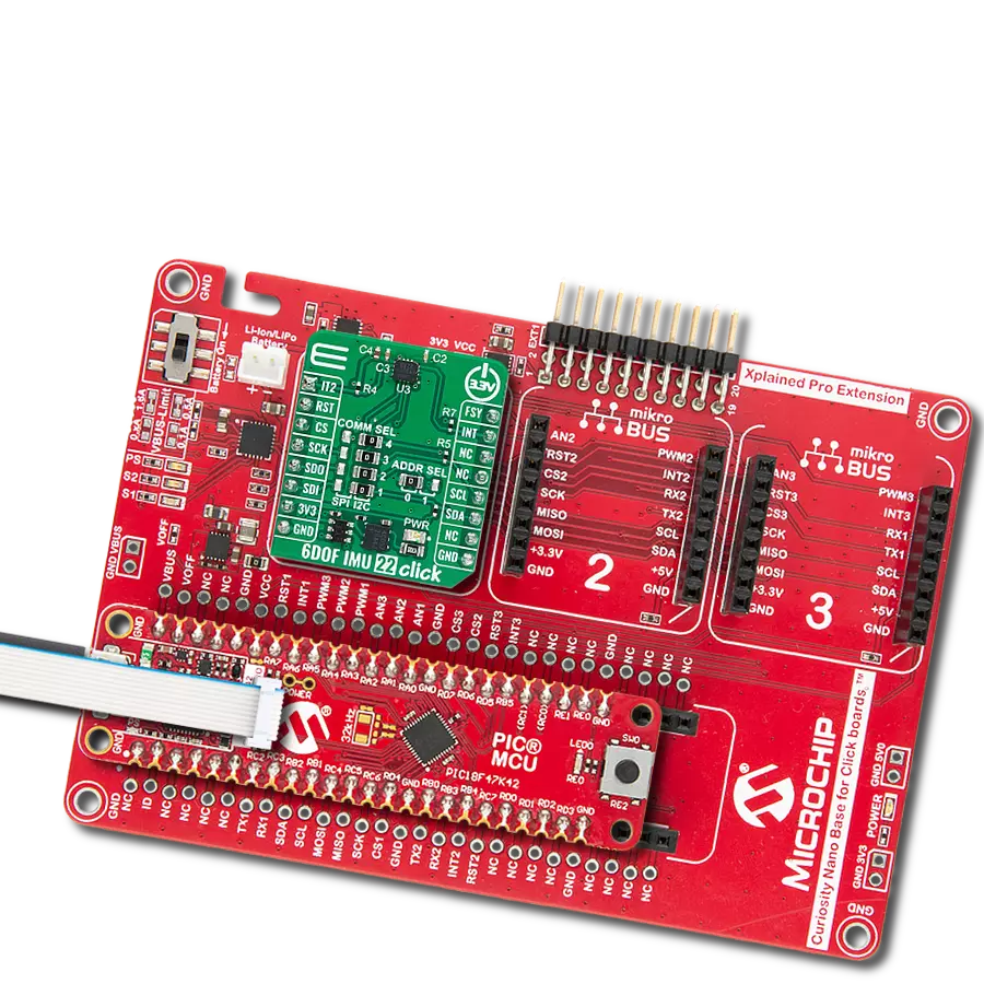
Clicker 2 for Kinetis is a compact starter development board that brings the flexibility of add-on Click boards™ to your favorite microcontroller, making it a perfect starter kit for implementing your ideas. It comes with an onboard 32-bit ARM Cortex-M4F microcontroller, the MK64FN1M0VDC12 from NXP Semiconductors, two mikroBUS™ sockets for Click board™ connectivity, a USB connector, LED indicators, buttons, a JTAG programmer connector, and two 26-pin headers for interfacing with external electronics. Its compact design with clear and easily recognizable silkscreen markings allows you to build gadgets with unique functionalities and
features quickly. Each part of the Clicker 2 for Kinetis development kit contains the components necessary for the most efficient operation of the same board. In addition to the possibility of choosing the Clicker 2 for Kinetis programming method, using a USB HID mikroBootloader or an external mikroProg connector for Kinetis programmer, the Clicker 2 board also includes a clean and regulated power supply module for the development kit. It provides two ways of board-powering; through the USB Micro-B cable, where onboard voltage regulators provide the appropriate voltage levels to each component on the board, or
using a Li-Polymer battery via an onboard battery connector. All communication methods that mikroBUS™ itself supports are on this board, including the well-established mikroBUS™ socket, reset button, and several user-configurable buttons and LED indicators. Clicker 2 for Kinetis is an integral part of the Mikroe ecosystem, allowing you to create a new application in minutes. Natively supported by Mikroe software tools, it covers many aspects of prototyping thanks to a considerable number of different Click boards™ (over a thousand boards), the number of which is growing every day.

Microcontroller Overview
MCU Card / MCU

Architecture
ARM Cortex-M4
MCU Memory (KB)
1024
Silicon Vendor
NXP
Pin count
121
RAM (Bytes)
262144
Used MCU Pins
mikroBUS™ mapper
Take a closer look
Schematic
Step by step
Project assembly

Start by selecting your development board and Click board™. Begin with the Clicker 2 for Kinetis as your development board.


Track your results in real time
Application Output
After loading the code example, pressing the "DEBUG" button builds and programs it on the selected setup.

After programming is completed, a header with buttons for various actions available in the IDE appears. By clicking the green "PLAY "button, we start reading the results achieved with Click board™.

Upon completion of programming, the Application Output tab is automatically opened, where the achieved result can be read. In case of an inability to perform the Debug function, check if a proper connection between the MCU used by the setup and the CODEGRIP programmer has been established. A detailed explanation of the CODEGRIP-board connection can be found in the CODEGRIP User Manual. Please find it in the RESOURCES section.

Software Support
Library Description
This library contains API for Thermo 20 Click driver.
Key functions:
thermo20_set_cmd- Send command function.thermo20_start_conversion- Start conversion function.thermo20_get_temperature- Get temperature data function.
Open Source
Code example
This example can be found in NECTO Studio. Feel free to download the code, or you can copy the code below.
/*!
 * @file main.c
 * @brief Thermo20 Click example
 *
 * # Description
 * This example showcases the ability of Thermo 20 Click board to
 * read it's serial number. It can read themperature and measure from -40degC to
 * 120degC.
 *
 * The demo application is composed of two sections :
 *
 * ## Application Init
 * Initialization communication modules(I2C, UART). Resets device and read Serial Number.
 *
 * ## Application Task
 * In span of ~ 1000ms it sends command for adc conversion of temperature, reads ADC value,
 * and calculates temperature in degrees C.
 *
 * @note For this driver to work on 18bit PIC MCU-s you need to additionally pull up communication lines.
 *
 * @author Mikroe Team
 *
 */

#include "board.h"
#include "log.h"
#include "thermo20.h"

static thermo20_t thermo20;
static log_t logger;

void application_init ( void )
{
    log_cfg_t log_cfg;  /**< Logger config object. */
    thermo20_cfg_t thermo20_cfg;  /**< Click config object. */

    /**
     * Logger initialization.
     * Default baud rate: 115200
     * Default log level: LOG_LEVEL_DEBUG
     * @note If USB_UART_RX and USB_UART_TX
     * are defined as HAL_PIN_NC, you will
     * need to define them manually for log to work.
     * See @b LOG_MAP_USB_UART macro definition for detailed explanation.
     */
    LOG_MAP_USB_UART( log_cfg );
    log_init( &logger, &log_cfg );
    log_info( &logger, " Application Init " );

    // Click initialization.
    thermo20_cfg_setup( &thermo20_cfg );
    THERMO20_MAP_MIKROBUS( thermo20_cfg, MIKROBUS_1 );
    err_t init_flag = thermo20_init( &thermo20, &thermo20_cfg );
    if ( I2C_MASTER_ERROR == init_flag )
    {
        log_error( &logger, " Application Init Error. " );
        log_info( &logger, " Please, run program again... " );

        for ( ; ; );
    }

    thermo20_default_cfg ( &thermo20 );

    uint32_t ser_numb = thermo20_get_serial_number( &thermo20 );
    log_printf( &logger, " > Serial Number: %lu\r\n", ser_numb );

    log_info( &logger, " Application Task " );
}

void application_task ( void )
{
    thermo20_start_conversion( &thermo20 );

    float temperature = thermo20_get_temperature( &thermo20 );

    log_printf( &logger, " > Temperature[deg C]: %.2f\r\n", temperature );

    Delay_ms( 1000 );
}

void main ( void )
{
    application_init( );

    for ( ; ; )
    {
        application_task( );
    }
}

// ------------------------------------------------------------------------ END