
Published 5月 15, 2025
Show & Speak Digits Via Knob Solution
旋转旋钮,看到数字,听到读数 —— 一个直观的模拟转视觉与语音界面,完美适用于交互式嵌入式应用
你将学到和构建的内容
简介
Show & Speak Digits Via Knob 解决方案通过结合 POT 4 Click、Speaker 2 Click 和 16x12 G Click,构建了一个有趣的交互式系统,将旋钮的模拟输入转换为同步的视觉与语音反馈。随着电位器旋转,系统会将输入电压映射为六个数字中的一个,并在 LED 点阵屏上显示该数字,同时通过预录语音将其读出。POT 4 Click 上的按钮还可触发音效,增强用户互动体验。该方案非常适用于用户界面原型开发、STEM 教育或无障碍演示,直观展示了嵌入式系统中模拟输入到多媒体输出的完整转换过程。
mikroBUS 1
16x12 G Click
16x12 G Click 是一款紧凑型附加板,用于控制和可视化复杂的 LED 点阵图案。该板基于 Lumissil Microsystems 的 IS31FL3733 点阵 LED 驱动器,搭载一个 16x12 的 LED 点阵,总计 192 颗 LED,每颗都可独立控制开关状态并支持通过 8 位 PWM 进行亮度调节,实现 256 级亮度控制。该驱动器支持三种自动呼吸模式(Auto Breath Mode),可创建动态光效,提升视觉表现力。通信采用 I2C 接口,同时还通过 mikroBUS™ 提供额外的控制引脚(INT、RST 和 CS),实现更灵活的模块控制。该板兼容 3.3V 与 5V 逻辑电平,可通过跳线进行选择,从而适配各种微控制器平台。配套的软件库与示例代码可帮助开发者快速实现集成与功能自定义,非常适用于嵌入式应用中的状态指示、仪表面板、交互式灯光设计或动画显示等场景。

mikroBUS 2
Speaker 2 Click
Speaker 2 Click 是一款紧凑型附加板,适用于高品质音频播放和语音提示应用。该板采用 Nuvoton 的 ISD2360 三通道数字 ChipCorder® 芯片,集成了非易失性闪存用于音频存储与回放。ISD2360 支持最长达 64 秒的语音存储,具备数字解压、独立多通道播放功能,并内建 Class D 扬声器驱动器,可直接驱动板载的 AS01508AO-SC-R 扬声器。该模块通过标准 SPI 接口与主控 MCU 通信,具备可配置的 I/O 引脚和内建程序验证机制,在外部组件极少的情况下确保系统运行可靠。板上还提供可切换的逻辑电压选择(3.3V 或 5V)以及用于独立数字供电的跳线设置。Speaker 2 Click 非常适合嵌入式系统中需要清晰语音提示、音效或预录消息的场景,如自动化系统、消费类电子产品和工业控制设备。

mikroBUS 3
POT 4 Click
POT 4 Click 是一款紧凑型扩展板,具备精确可选的参考电压输出功能。该板配备 Bourns 出品的 PRS11R-425F-S103B1 高质量 11mm 旋转电位器,电阻值为 10kΩ。PRS11R-425F-S103B1 具有小巧的外形尺寸,带有按压式瞬时开关、平头轴结构,并支持宽工作温度范围。该板还集成了高分辨率的 12 位模数转换器(ADC),能够检测到最微小的旋转位移并对位置进行数字化处理,配合轨到轨缓冲运算放大器,确保输入和输出阻抗稳定。用户可选择以模拟或数字形式处理输出信号。此 Click board™ 广泛应用于音频与照明控制、实验室设备、工业自动化控制等对电位器可靠性有较高要求的场景。

功能概述
开发板
UNI-DS v8 是一款功能强大的开发板,专为快速嵌入式应用开发而设计,支持多种 MCU(STM32、Kinetis、TIVA、PIC、AVR 等),并配备全球首款内置 WiFi 调试器/编程器。它集成了先进的 CODEGRIP 模块,支持 JTAG、SWD 和 SWO Trace 调试,并提供多种输入选项的稳压电源(USB-C、12V、电池)。此外,该开发板具备丰富的连接选项,包括 USB-UART、USB HOST/DEVICE、CAN 和以太网。借助 mikroBUS™、SiBRAIN 插槽以及双显示支持,它可无缝融入 MIKROE 生态系统,兼容所有 Click boards™,为高效、沉浸式的原型开发提供理想平台。

微控制器概述
MCU卡片 / MCU
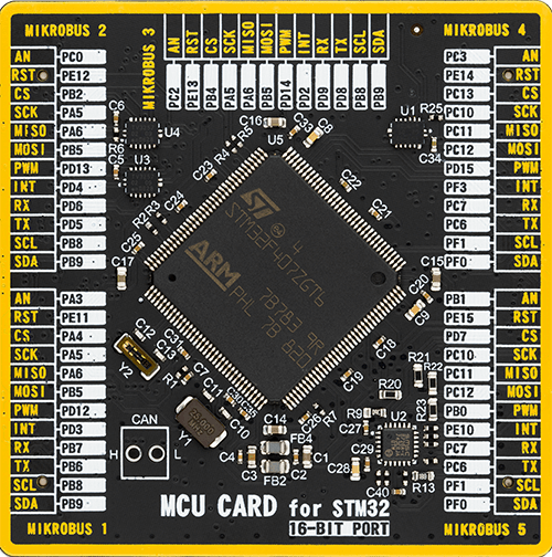
类型
8th Generation
建筑
ARM Cortex-M4
MCU 内存 (KB)
1024
硅供应商
STMicroelectronics
引脚数
144
RAM (字节)
196608
一步一步来
项目组装
首先,选择您的开发板 - UNI-DS v8


实时跟踪您的结果
应用程序输出
1. 应用程序输出 - 在调试模式下,“应用程序输出”窗口支持实时数据监控,直接提供执行结果的可视化。请按照提供的教程正确配置环境,以确保数据正确显示。

2. UART 终端 - 使用UART Terminal通过USB to UART converter监视数据传输,实现Click board™与开发系统之间的直接通信。请根据项目需求配置波特率和其他串行设置,以确保正常运行。有关分步设置说明,请参考提供的教程。

3. Plot 输出 - Plot功能提供了一种强大的方式来可视化实时传感器数据,使趋势分析、调试和多个数据点的对比变得更加直观。要正确设置,请按照提供的教程,其中包含使用Plot功能显示Click board™读数的分步示例。在代码中使用Plot功能时,请使用以下函数:plot(insert_graph_name, variable_name);。这是一个通用格式,用户需要将“insert_graph_name”替换为实际图表名称,并将“variable_name”替换为要显示的参数。

软件支持
库描述
Show & Speak Digits Via Knob Solution 使用 NECTO Studio 开发,确保兼容 mikroSDK 的开源库和工具。该解决方案采用即插即用的设计,支持快速实施和测试,并与所有配备 mikroBUS™ 插座的开发板、入门套件和 mikromedia 板完全兼容。
示例描述
Show & Speak Digits Via Knob 应用程序将旋转电位器的位置(从 0% 到 100%)映射为六个预定义范围中的一个,每个范围对应一个数字(1 至 6)。该数字会显示在 16x12 G Click 的 LED 点阵屏上,同时通过 Speaker 2 Click 播放相应的语音提示。POT 4 Click 板载按钮还可触发一个快速蜂鸣音效,增强交互体验。系统会通过 UART 实时记录电压读数和语音播放状态,方便调试与追踪。
关键功能:
pot4_read_voltage- 读取来自 POT 4 Click 的电位器模拟电压。pot4_convert_voltage_to_percents- 将电压值转换为 0–100% 的百分比表示。pot4_get_switch_pin- 检测 POT 4 Click 板载按钮的当前状态。speaker2_play_voice- 播放 Speaker 2 Click 存储中的预录语音提示或音效。c16x12g_display_byte- 在 16x12 G Click LED 点阵屏上显示单个数字(例如 '1' 到 '6')。c16x12g_clear_display- 清除显示屏,为新字符显示做准备。c16x12g_display_text- 在初始化期间滚动显示欢迎信息。log_printf- 将电压读数和语音事件状态记录到 UART。
应用初始化
初始化阶段首先配置 UART 日志记录以实现状态输出。重置并初始化 16x12 G Click,设置为最大亮度,并启用 ABM 模式以实现平滑的动画显示。LED 点阵上滚动显示欢迎文本:“Show & Speak Digits”。随后初始化 Speaker 2 Click,加载默认语音项目。接着配置 POT 4 Click 以进行模拟电压采集与按钮状态检测。各模块准备就绪后,系统即进入交互式模拟转视听操作状态。
应用任务
主循环中,系统持续监测 POT 4 Click 的电位器位置。读取模拟电压后转换为百分比,再将其映射为 1–6 之间的某个数字。相应数字将在 16x12 G Click 上显示,同时对应语音在 Speaker 2 Click 上播放。如用户按下 POT 4 Click 的按钮,将立即触发一个快速蜂鸣音效。每次操作,包括电压百分比与语音播放状态,都会通过 UART 输出记录。该交互循环无限运行,实现对用户旋钮输入的实时响应与反馈。
开源
代码示例
完整的应用程序代码和一个现成的项目可以通过NECTO Studio包管理器直接安装到NECTO Studio。 应用程序代码也可以在MIKROE的GitHub账户中找到。
/*
 * Solution Name: Show & Speak Digits Via Knob
 *
 * Description:
 * This interactive embedded solution combines LED matrix output, audio
 * playback, and analog input sensing for dynamic digit representation.
 * It utilizes the 16x12 G Click to display a digit (1?6), while the Speaker 2
 * Click plays the corresponding pre-recorded voice prompt. The digit
 * displayed and sound played are determined by the position of the
 * potentiometer on the POT 4 Click.
 *
 * Users rotate the potentiometer, and the system reads the analog voltage,
 * converts it to a percentage (0?100%), and maps it to one of six digit/voice
 * pairs. A button press on the POT 4 Click triggers an additional fast beep
 * sound.
 *
 * The system utilizes the following Click boards:
 *   - **16x12 G Click**: 16x12 LED matrix that displays digits with ABM
 *     animation.
 *   - **Speaker 2 Click**: Plays SPI-triggered audio files such as spoken
 *     numbers and beeps.
 *   - **POT 4 Click**: Reads analog voltage from a potentiometer and converts
 *     it to percentage.
 *
 * The `application_init` function initializes all three Click boards, sets up
 * the LED matrix (with global brightness and animation timing), prepares the
 * Speaker 2 Click for playback, and initializes the analog voltage input logic
 * for the potentiometer.
 *
 * The `application_task` function continuously reads the potentiometer value
 * as a percentage and maps that to a digit (1?6). It clears the display, shows
 * the digit on the LED matrix, and plays the corresponding voice. If the onboard
 * button is pressed, a FAST BEEP sound is triggered. All actions are logged via
 * UART.
 *
 * Hardware Setup:
 *   - **MIKROBUS_1**: 16x12 G Click (LED matrix digit output)
 *   - **MIKROBUS_2**: Speaker 2 Click (SPI audio output)
 *   - **MIKROBUS_3**: POT 4 Click (Analog potentiometer input with digital
 *     switch)
 *
 * Key Features:
 *   - Real-time digit-to-voice mapping based on analog input.
 *   - Interactive rotary control using potentiometer.
 *   - Button-triggered sound feedback with fast beep tone.
 *   - Dynamic digit rendering with smooth LED animation.
 *   - Full UART logging for audio events and potentiometer readings.
 *
 * Development Environment:
 *   - **NECTO Studio** ([link](https://www.mikroe.com/necto))
 *   - **mikroSDK v2.0** ([link](https://www.mikroe.com/mikrosdk))
 *   - MIKROE **Click boards** ([link](https://www.mikroe.com/click-boards))
 *
 * Author: Branko Jaksic
 * Date: April, 2025
 */

// ------------------------------------------------------------------- INCLUDES
#include "log.h"
#include "pot4.h"
#include "board.h"
#include "c16x12.h"
#include "speaker2.h"

// ------------------------------------------------------------------ VARIABLES
// --- Driver Instances ---
static pot4_t pot4;                     // POT 4 Click driver object
static log_t logger;                    // Logger instance
static c16x12_t c16x12;                 // 16x12 G Click driver instance
static speaker2_t speaker2;             // Speaker 2 Click driver instance

// --- 16x12 G Click Configuration ---
static c16x12_abm_t abm_1;              // ABM animation configuration
static uint8_t scroll_speed = 50;       // Scroll speed for animated text

// --- Speaker 2 Click Voice Map ---
const uint8_t voices[6] = {             // Voice prompt mappings (1?6)
    SPEAKER2_VP9_ONE,
    SPEAKER2_VP10_TWO,
    SPEAKER2_VP11_THREE,
    SPEAKER2_VP12_FOUR,
    SPEAKER2_VP13_FIVE,
    SPEAKER2_VP14_SIX
};

// --- Display Digits & Label ---
const char digits[6] = { '1', '2', '3', '4', '5', '6' }; // Digits to display
char name[] = "Show & Speak Digits Via Knob";            // Welcome text

// ------------------------------------------------------ APPLICATION FUNCTIONS
void application_init ( void )
{
    log_cfg_t log_cfg;  /**< Logger config object. */
    pot4_cfg_t pot4_cfg;  /**< Click config object. */
    c16x12_cfg_t c16x12_cfg; /**< Click config object. */
    speaker2_cfg_t speaker2_cfg;  /**< Click config object. */

    /**
     * Logger initialization.
     * Default baud rate: 115200
     * Default log level: LOG_LEVEL_DEBUG
     * @note If USB_UART_RX and USB_UART_TX
     * are defined as HAL_PIN_NC, you will
     * need to define them manually for log to work.
     * See @b LOG_MAP_USB_UART macro definition for detailed explanation.
     */
    LOG_MAP_USB_UART( log_cfg );
    log_init( &logger, &log_cfg );
    log_info( &logger, " Application Init " );

    // 16x12 Click initialization.
    c16x12_cfg_setup( &c16x12_cfg );
    C16X12_MAP_MIKROBUS( c16x12_cfg, MIKROBUS_1 );
    c16x12_init( &c16x12, &c16x12_cfg );

    c16x12g_device_reset( &c16x12 );
    Delay_ms ( 1000 );

    c16x12_default_cfg( &c16x12 );
    c16x12g_set_global_current_control( &c16x12, 255 );
    c16x12g_set_leds_mode( &c16x12, C16X12G_LED_MODE_ABM1 );

    abm_1.time_1     = C16X12G_ABM_T1_210MS;
    abm_1.time_2     = C16X12G_ABM_T2_0MS;
    abm_1.time_3     = C16X12G_ABM_T3_210MS;
    abm_1.time_4     = C16X12G_ABM_T4_0MS;
    abm_1.loop_begin = C16X12G_ABM_LOOP_BEGIN_T1;
    abm_1.loop_end   = C16X12G_ABM_LOOP_END_T3;
    abm_1.loop_times = C16X12G_ABM_LOOP_FOREVER;

    c16x12g_config_abm( &c16x12, C16X12G_ABM_NUM_1, &abm_1 );
    c16x12g_start_abm( &c16x12 );
    c16x12g_display_text( &c16x12, &name[ 0 ], sizeof(name) - 1, scroll_speed );

    c16x12g_config_abm( &c16x12, C16X12G_ABM_NUM_1, &abm_1 );
    c16x12g_start_abm( &c16x12 );

    // Speaker 2 Click initialization.
    speaker2_cfg_setup( &speaker2_cfg );
    SPEAKER2_MAP_MIKROBUS( speaker2_cfg, MIKROBUS_2 );
    if ( SPI_MASTER_ERROR == speaker2_init( &speaker2, &speaker2_cfg ) )
    {
        log_error( &logger, " Communication init." );
        for ( ; ; );
    }

    if ( SPEAKER2_ERROR == speaker2_default_cfg ( &speaker2 ) )
    {
        log_error( &logger, " Default configuration." );
        for ( ; ; );
    }

    // POT 4 Click initialization.
    pot4_cfg_setup( &pot4_cfg );
    POT4_MAP_MIKROBUS( pot4_cfg, MIKROBUS_3 );
    err_t init_flag = pot4_init( &pot4, &pot4_cfg );
    if ( ( ADC_ERROR == init_flag ) || ( I2C_MASTER_ERROR == init_flag ) )
    {
        log_error( &logger, " Communication init." );
        for ( ; ; );
    }

    log_info( &logger, " Application Task " );
}

void application_task ( void )
{
    float voltage = 0;
    uint8_t pot_percent = 0;

    // Switch I2C communication to POT 4 Click
    i2c_master_set_slave_address(&pot4.i2c, pot4.slave_address);

    // Play a beep if POT had been pressed
    if ( !pot4_get_switch_pin ( &pot4 ) )
    {
        err_t beep_status = speaker2_play_voice( &speaker2,
                                                SPEAKER2_VP15_FAST_BEEP );
        log_printf( &logger, " Playing FAST BEEP: %s\r\n\n",
                    ( beep_status == SPEAKER2_OK ) ? "DONE" : "ERROR" );
    }

    // Read analog voltage from POT 4
    if ( POT4_OK == pot4_read_voltage( &pot4, &voltage ) )
    {
        pot_percent = ( uint8_t ) pot4_convert_voltage_to_percents( &pot4, voltage );
        log_printf( &logger, " Potentiometer : %u %%\r\n", pot_percent );

        // Map percentage [0-100] into 6 levels (0-5)
        uint8_t index = ( pot_percent * 6 ) / 101;  // Ensure max 5

        // Switch I2C communication to 16x12 G Click
        i2c_master_set_slave_address(&c16x12.i2c, c16x12.slave_address);

        // Display digit on LED matrix
        c16x12g_clear_display( &c16x12 );
        c16x12g_display_byte( &c16x12, digits[ index ] );

        // Play voice for the digit
        err_t status = speaker2_play_voice( &speaker2, voices[ index ] );
        log_printf( &logger, " Playing voice %d: %s\r\n\n",
                    index + 1, ( status == SPEAKER2_OK ) ? "DONE" : "ERROR" );
    }
}

int main ( void )
{
    /* Do not remove this line or clock might not be set correctly. */
    #ifdef PREINIT_SUPPORTED
    preinit();
    #endif

    application_init( );

    for ( ; ; )
    {
        application_task( );
    }

    return 0;
}

// ------------------------------------------------------------------------ END
额外支持
资源
类别:Human-Machine Interface (HMI)


