使用AD5142A和STM32L496AG在您的项目中追求完美
告别模拟限制
已发布 7月 22, 2025
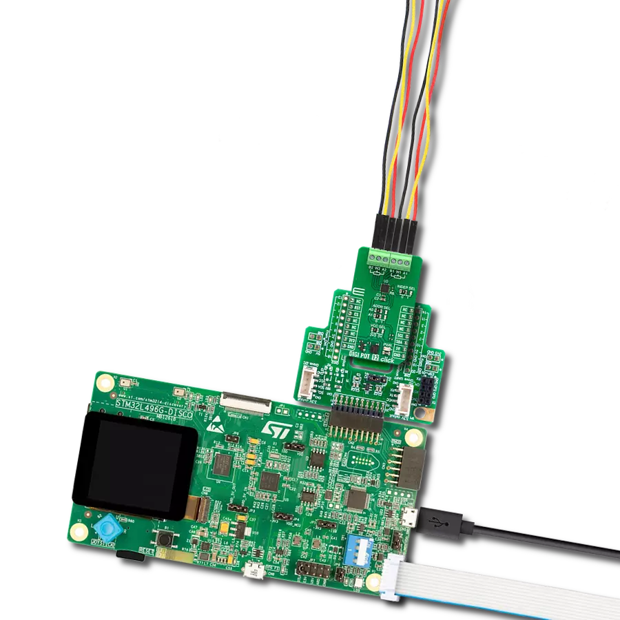
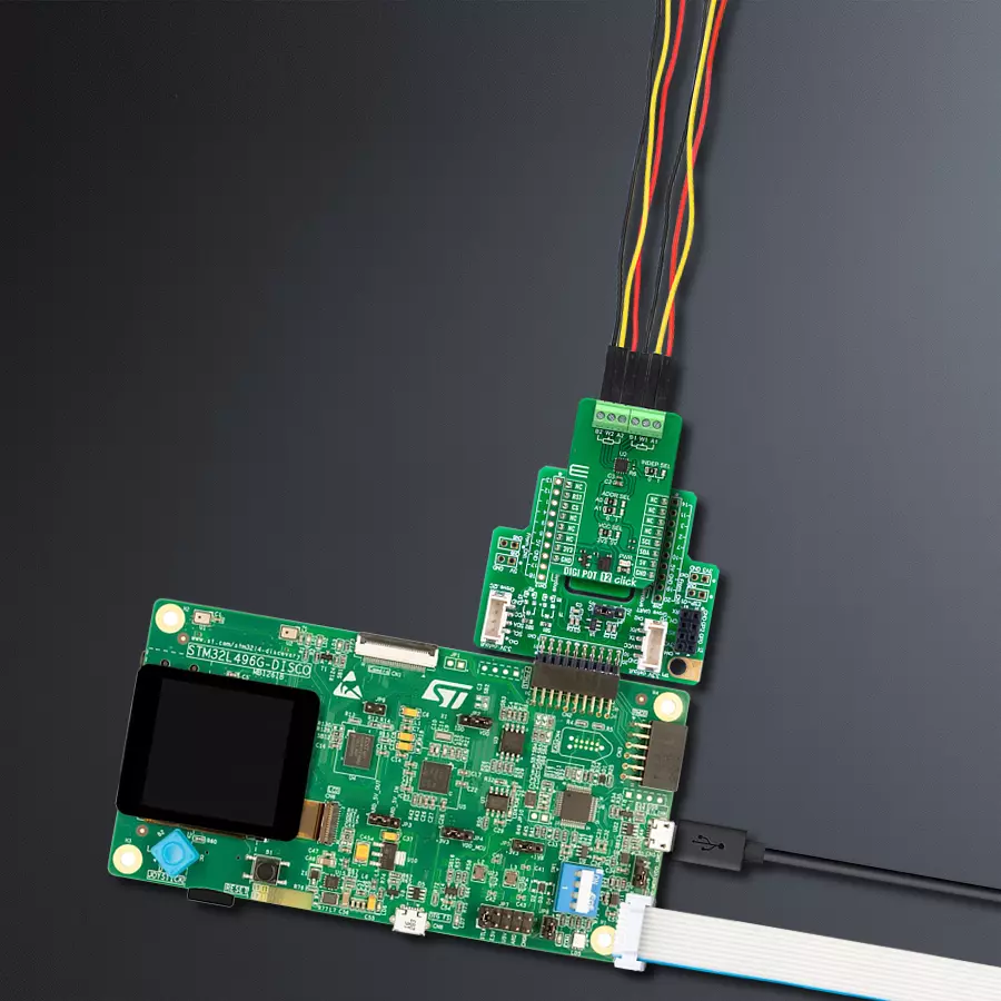
点击板
DIGI POT 12 Click
开发板
Discovery kit with STM32L496AG MCU
编译器
NECTO Studio
微控制器单元
STM32L496AG
通过我们的数字电位器释放电子电路的最大潜力,达到无与伦比的精度——这是实现每个应用高性能和高效率的关键。
A
A
硬件概览
它是如何工作的?
DIGI POT 12 Click基于Analog Devices的AD5142A,这是一款双通道、256位置非易失性数字电位器。电阻滑动触点位置由RDAC寄存器内容决定,该寄存器作为暂存器,允许无限次更改电阻设置。暂存器可以通过标准I2C接口加载16位数据字来编程任何位置设置。RDAC在端子A和端子B之间的标称电阻(RAB)为10KΩ,8位RDAC锁存数据解码以选择256个可能滑动触点设置中的一个。当找到所需位置时,可以将该值存储在板载EEPROM存储器中,从而在后续上电时始终恢复滑动触点位置。
EEPROM数据可以独立读取、写入并通过软件保护。该Click板™通过标准双线I2C接口与MCU通信,并以标准(100KHz)和快速(400KHz)数据传输模式运行。I2C地址可以通过默认设置为0的ADDR SEL跳线选择。还有一个RST引脚用于从EEPROM重置数字电位器的RDAC寄存器,低电平有效。此外,该Click板™带有INDEP SEL跳线,允许选择电位器模式和线性增益设置模式,默认设置为电位器模式(0)。线性增益设置模式可以将电位器控制为两个连接在单点的独立变阻器。一旦设置跳
线,软件不能将其关闭。此外,还有突发模式,可以将多个数据字节发送到主机MCU。关断模式将RDAC置于零功耗状态,而EEPROM中的数据保持不变。B、W和A端子之间没有极性限制,但它们不能高于VCC(最大5V)或低于VSS(0V)。该Click板™可以通过VCC SEL跳线选择使用3.3V或5V逻辑电压电平,从而使3.3V和5V的MCU都能够正确使用通信线路。此外,该Click板™配备了包含易于使用的功能库和示例代码的库,可以作为进一步开发的参考。

功能概述
开发板
32L496GDISCOVERY Discovery 套件是一款功能全面的演示和开发平台,专为搭载 Arm® Cortex®-M4 内核的 STM32L496AG 微控制器设计。该套件适用于需要在高性能、先进图形处理和超低功耗之间取得平衡的应用,支持无缝原型开发,适用于各种嵌入式解决方案。STM32L496AG 采用创新的节能架构,集成
了扩展 RAM 和 Chrom-ART 图形加速器,在提升图形性能的同时保持低功耗,使其特别适用于音频处理、图形用户界面和实时数据采集等对能效要求较高的应用。为了简化开发流程,该开发板配备了板载 ST-LINK/V2-1 调试器/编程器,提供即插即用的调试和编程体验,使用户无需额外硬件即可轻松加载、调
试和测试应用程序。凭借低功耗特性、增强的内存能力以及内置调试工具,32L496GDISCOVERY 套件是开发先进嵌入式系统、实现高效能解决方案的理想选择。

微控制器概述
MCU卡片 / MCU

建筑
ARM Cortex-M4
MCU 内存 (KB)
1024
硅供应商
STMicroelectronics
引脚数
169
RAM (字节)
327680
使用的MCU引脚
mikroBUS™映射器
“仔细看看!”
Click board™ 原理图

一步一步来
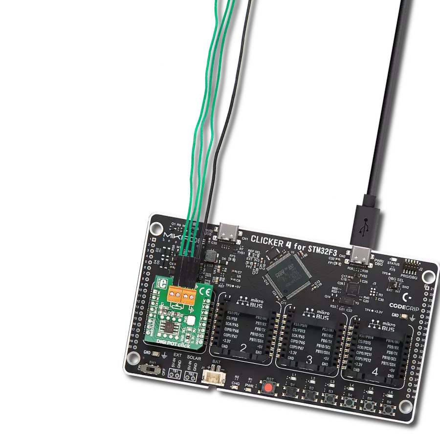
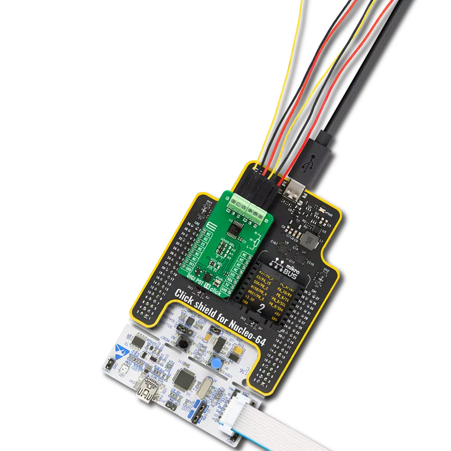
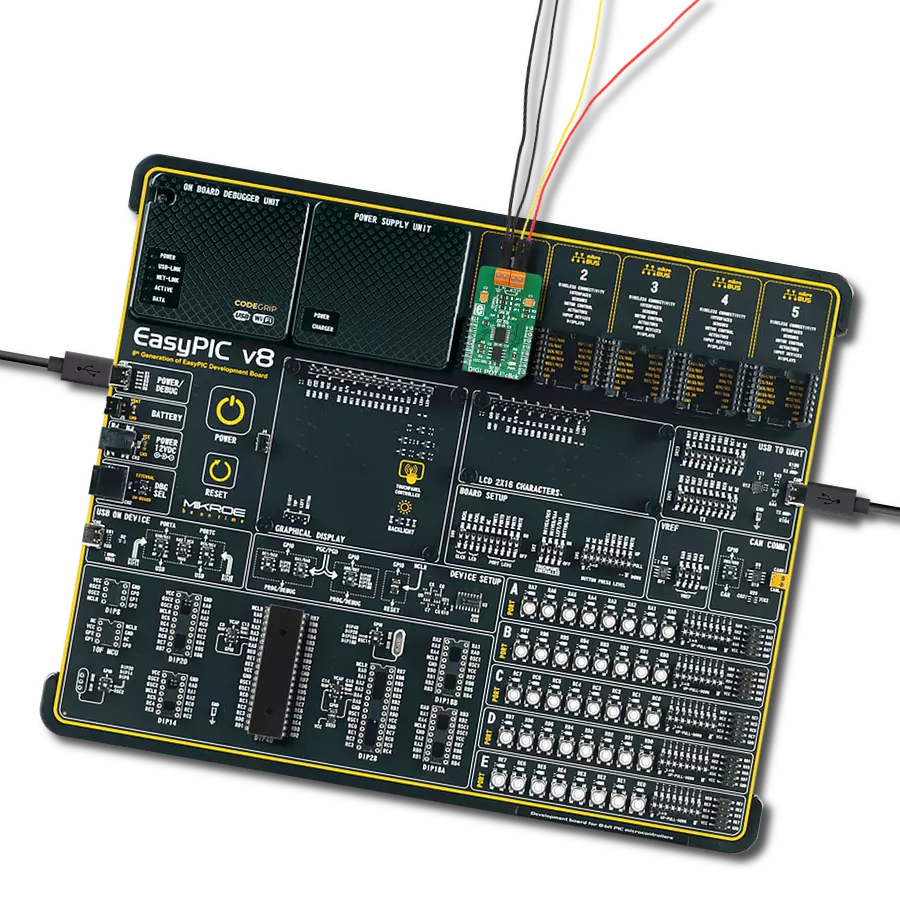
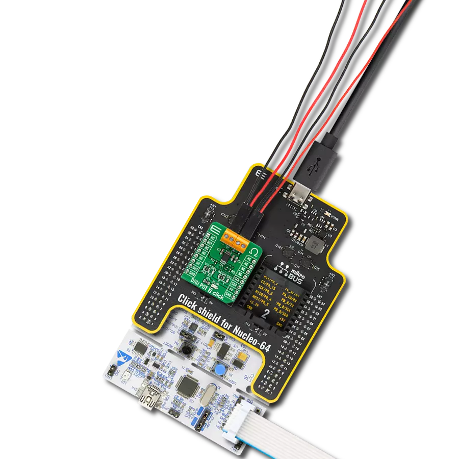
项目组装

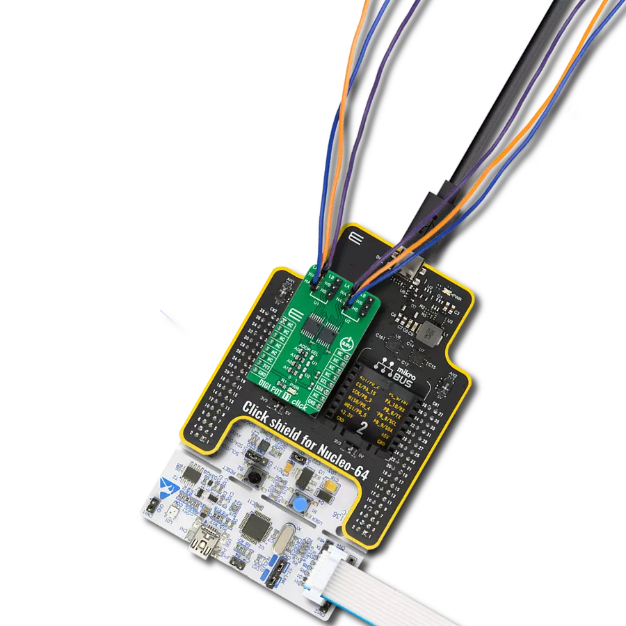
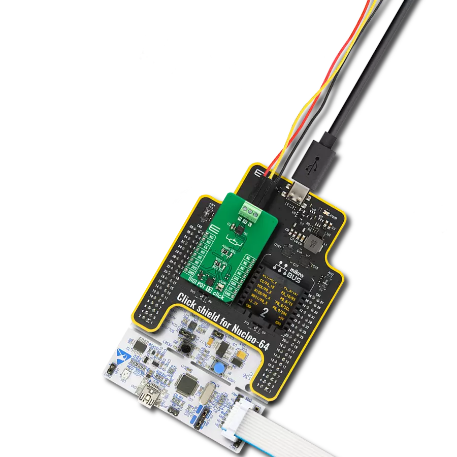
从选择您的开发板和Click板™开始。以Discovery kit with STM32L496AG MCU作为您的开发板开始。


实时跟踪您的结果
应用程序输出
1. 应用程序输出 - 在调试模式下,“应用程序输出”窗口支持实时数据监控,直接提供执行结果的可视化。请按照提供的教程正确配置环境,以确保数据正确显示。

2. UART 终端 - 使用UART Terminal通过USB to UART converter监视数据传输,实现Click board™与开发系统之间的直接通信。请根据项目需求配置波特率和其他串行设置,以确保正常运行。有关分步设置说明,请参考提供的教程。

3. Plot 输出 - Plot功能提供了一种强大的方式来可视化实时传感器数据,使趋势分析、调试和多个数据点的对比变得更加直观。要正确设置,请按照提供的教程,其中包含使用Plot功能显示Click board™读数的分步示例。在代码中使用Plot功能时,请使用以下函数:plot(insert_graph_name, variable_name);。这是一个通用格式,用户需要将“insert_graph_name”替换为实际图表名称,并将“variable_name”替换为要显示的参数。

软件支持
库描述
该库包含 DIGI POT 12 Click 驱动程序的 API。
关键功能:
digipot12_set_resistance- DIGI POT 12 设置电阻功能。digipot12_get_resistance- DIGI POT 12 获取电阻功能。
开源
代码示例
完整的应用程序代码和一个现成的项目可以通过NECTO Studio包管理器直接安装到NECTO Studio。 应用程序代码也可以在MIKROE的GitHub账户中找到。
/*!
 * @file main.c
 * @brief DIGI POT 12 Click example
 *
 * # Description
 * This library contains API for DIGI POT 12 Click driver.
 * The demo application uses a digital potentiometer
 * to change the resistance values of both channels.
 *
 * The demo application is composed of two sections :
 *
 * ## Application Init
 * The initialization of I2C module, log UART, and additional pins.
 * After the driver init, the app executes a default configuration.
 *
 * ## Application Task
 * This example demonstrates the use of the DIGI POT 12 Click board™.
 * The demo application iterates through the entire wiper range and
 * sets the resistance of both channels in steps of approximately 1kOhm.
 * Results are being sent to the UART Terminal, where you can track their changes.
 *
 * @author Nenad Filipovic
 *
 */

#include "board.h"
#include "log.h"
#include "digipot12.h"

static digipot12_t digipot12;
static log_t logger;

void application_init ( void )
{
    log_cfg_t log_cfg;  /**< Logger config object. */
    digipot12_cfg_t digipot12_cfg;  /**< Click config object. */

    /**
     * Logger initialization.
     * Default baud rate: 115200
     * Default log level: LOG_LEVEL_DEBUG
     * @note If USB_UART_RX and USB_UART_TX
     * are defined as HAL_PIN_NC, you will
     * need to define them manually for log to work.
     * See @b LOG_MAP_USB_UART macro definition for detailed explanation.
     */
    LOG_MAP_USB_UART( log_cfg );
    log_init( &logger, &log_cfg );
    log_info( &logger, " Application Init " );

    // Click initialization.
    digipot12_cfg_setup( &digipot12_cfg );
    DIGIPOT12_MAP_MIKROBUS( digipot12_cfg, MIKROBUS_1 );
    if ( I2C_MASTER_ERROR == digipot12_init( &digipot12, &digipot12_cfg ) )
    {
        log_error( &logger, " Communication init." );
        for ( ; ; );
    }

    if ( DIGIPOT12_ERROR == digipot12_default_cfg ( &digipot12 ) )
    {
        log_error( &logger, " Default configuration." );
        for ( ; ; );
    }

    log_info( &logger, " Application Task " );
    log_printf( &logger, " ----------------------------\r\n" );
    Delay_ms ( 100 );
}

void application_task ( void )
{
    static float res_kohm;
    for ( uint8_t n_cnt = DIGIPOT12_RES_0_KOHM; n_cnt <= DIGIPOT12_RES_10_KOHM; n_cnt++ )
    {
        if ( DIGIPOT12_OK == digipot12_set_resistance( &digipot12, DIGIPOT12_WIPER_SEL_1, ( float ) n_cnt ) )
        {
            if ( DIGIPOT12_OK == digipot12_get_resistance( &digipot12, DIGIPOT12_WIPER_SEL_1, &res_kohm ) )
            {
                log_printf( &logger, " Rwb1 : %.2f kOhm\r\n", res_kohm );
                Delay_ms ( 100 );
            }
        }

        if ( DIGIPOT12_OK == digipot12_set_resistance( &digipot12, DIGIPOT12_WIPER_SEL_2, ( float ) ( DIGIPOT12_RES_10_KOHM - n_cnt ) ) )
        {
            if ( DIGIPOT12_OK == digipot12_get_resistance( &digipot12, DIGIPOT12_WIPER_SEL_2, &res_kohm ) )
            {
                log_printf( &logger, " Rwb2 : %.2f kOhm\r\n", res_kohm );
                Delay_ms ( 100 );
            }
        }
        log_printf( &logger, " ----------------------------\r\n" );
        Delay_ms ( 1000 );
        Delay_ms ( 1000 );
        Delay_ms ( 1000 );
        Delay_ms ( 1000 );
        Delay_ms ( 1000 );
    }
}

int main ( void )
{
    /* Do not remove this line or clock might not be set correctly. */
    #ifdef PREINIT_SUPPORTED
    preinit();
    #endif

    application_init( );

    for ( ; ; )
    {
        application_task( );
    }

    return 0;
}

// ------------------------------------------------------------------------ END