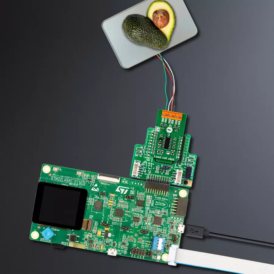
使用HX711和STM32L496AG体验快速可靠的重量读取便利性
提升每一盎司的测量精度
已发布 7月 22, 2025
点击板
Load cell click
开发板
Discovery kit with STM32L496AG MCU
编译器
NECTO Studio
微控制器单元
STM32L496AG
通过可靠和一致的体重跟踪,监控和管理您的健康旅程。
A
A
硬件概览
它是如何工作的?
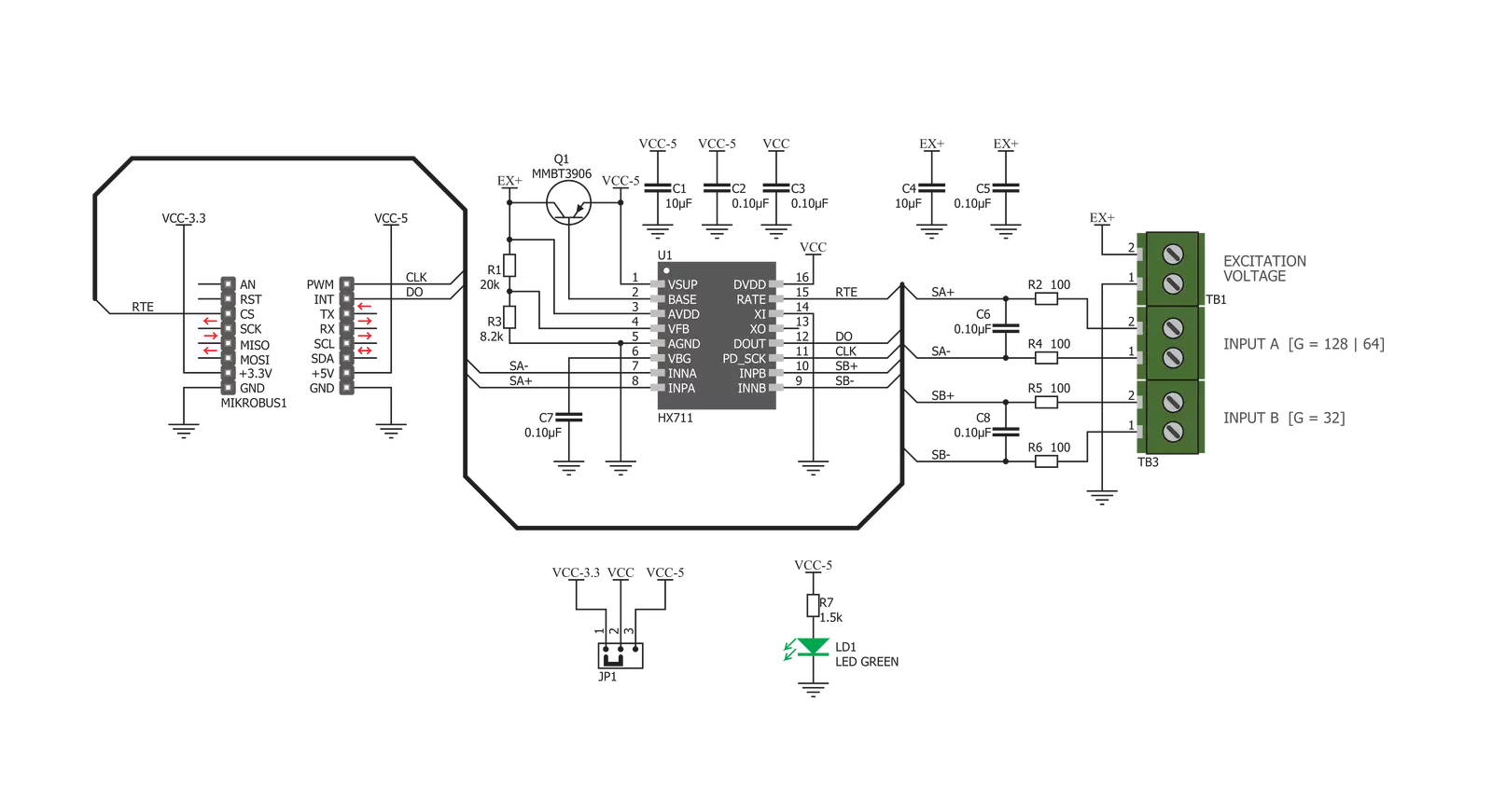
Load Cell Click 基于 Avia Semiconductor 的 HX711,这是一款专为称重应用设计的 24 位模数转换器(ADC)。该设备包含两个高分辨率(24 位)ADC,具有差分输入和内部低噪声可编程增益放大器。由于输入电压非常低,需要从连接到输入端子的称重传感器中获得最佳的信噪比。称重传感器通常有四个应变计,它们是平面电阻器,由于几何形状的变化,在受压或受拉时会改变其电阻。称重传感器通常是具有足够弹性的金属块,耐材料疲劳,因此在需要重新校准之前可以承受多次测量。当对称重传感器施加应变力时,形成惠斯通电桥的一对应变计将被拉伸,而另一对应变计将被压缩。电桥两端会出现一个小电压差,与施加的应变力成正比。这个电压差在 mV 范围内,可以通过测量和采样读取应变力强度。因此,称重传感器形成一个传感器,直接将施加的力转换为电压。正如前面提到的,HX711 IC 的主要任务是尽可能准确地采样电桥两端的电压,并且噪声最小。应变计形成的惠斯通电桥连接
到一个激励电源,以便检测电阻变化。HX711 有一个专用的稳压电压输出,提供必要的激励电压。两个差分输入连接负载,提供各种增益因子。第一个差分输入(标记为 A)提供 64 倍或 128 倍的可选增益。第二个差分输入(标记为 B)提供固定的 32 倍增益。这提供了根据所用称重传感器和应变力大小选择所需增益因子的可能性。Load Cell Click 使用片上时钟振荡器进行串行通信。数据输出速率是可选的,取决于连接到 mikroBUS™ CS 引脚的 RTE 引脚的逻辑状态。该引脚上的高逻辑电平将设置数据输出速率为每秒 80 个样本(SPS),而低逻辑电平将设置数据速率为每秒 10 个样本(SPS)。HX711 IC 的串行通信相当特殊。当数据输出引脚(DO)变为低逻辑电平时,主微控制器(MCU)可以开始在 SCK 引脚上生成时钟脉冲。数据在接下来的 24 个脉冲中时钟输出,而第 25 个时钟脉冲将再次将 DO 引脚设置为高逻辑电平。在 DO 引脚变为低逻辑电平后,时钟脉冲的数量用于确定下
次转换的增益级别和 ADC 通道。例如,如果在 DO 引脚变为低逻辑电平后应用 27 个脉冲,则下一次转换将从通道 A 时钟输出数据,并将增益放大器(PGA)设置为 64 倍。有关通信协议的更多信息可以在 HX711 数据手册中找到。然而,芯片通信由附带 Click board™ 的库处理,该库包含简单易用的功能,与所有 MikroElektronika 编译器兼容。SCK 引脚也用于关闭 IC:如果 SCK 引脚保持高电平超过 60µs,HX711 IC 将进入掉电模式。只要引脚被拉到低逻辑电平(假设仍然存在有效电源),IC 将重新上电并将寄存器重置为默认值(输入 A,PGA 设置为 128 倍)。此 Click board™ 可通过 VCC SEL 跳线选择在 3.3V 或 5V 逻辑电压水平下工作。这样,3.3V 和 5V 兼容的 MCU 都可以正确使用通信线路。此外,此 Click board™ 配备了一个库,包含易于使用的函数和示例代码,可用作进一步开发的参考。

功能概述
开发板
32L496GDISCOVERY Discovery 套件是一款功能全面的演示和开发平台,专为搭载 Arm® Cortex®-M4 内核的 STM32L496AG 微控制器设计。该套件适用于需要在高性能、先进图形处理和超低功耗之间取得平衡的应用,支持无缝原型开发,适用于各种嵌入式解决方案。STM32L496AG 采用创新的节能架构,集成
了扩展 RAM 和 Chrom-ART 图形加速器,在提升图形性能的同时保持低功耗,使其特别适用于音频处理、图形用户界面和实时数据采集等对能效要求较高的应用。为了简化开发流程,该开发板配备了板载 ST-LINK/V2-1 调试器/编程器,提供即插即用的调试和编程体验,使用户无需额外硬件即可轻松加载、调
试和测试应用程序。凭借低功耗特性、增强的内存能力以及内置调试工具,32L496GDISCOVERY 套件是开发先进嵌入式系统、实现高效能解决方案的理想选择。

微控制器概述
MCU卡片 / MCU

建筑
ARM Cortex-M4
MCU 内存 (KB)
1024
硅供应商
STMicroelectronics
引脚数
169
RAM (字节)
327680
使用的MCU引脚
mikroBUS™映射器
“仔细看看!”
Click board™ 原理图
一步一步来
项目组装

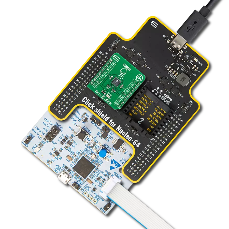
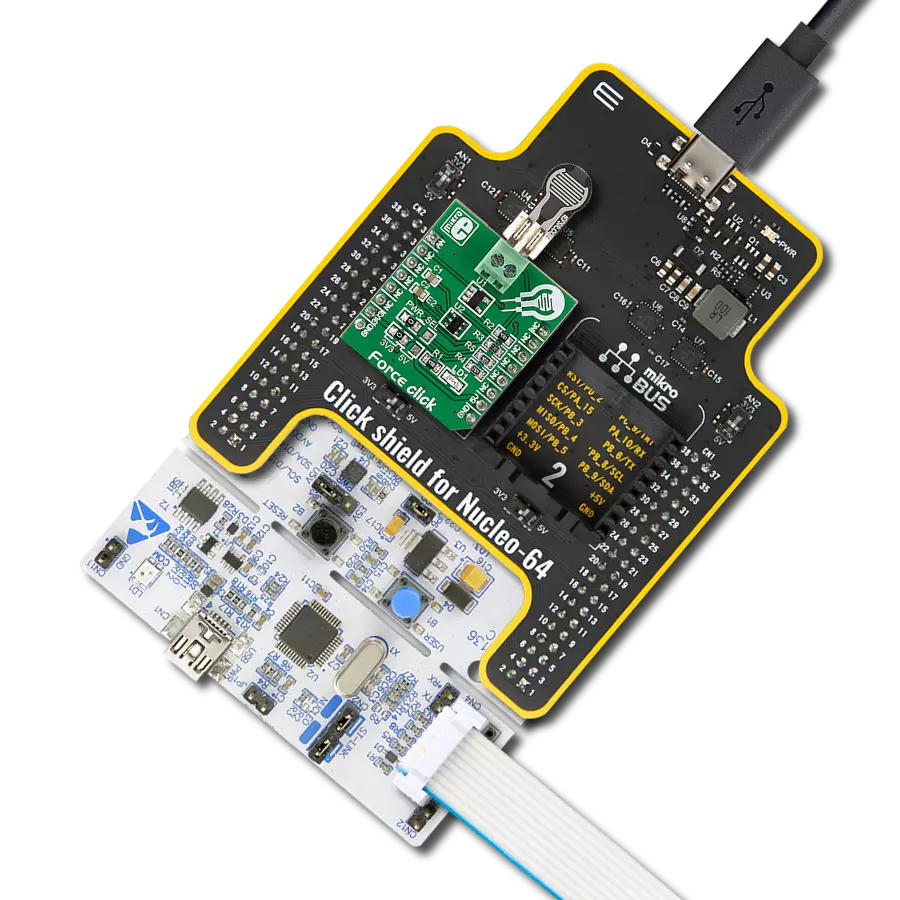
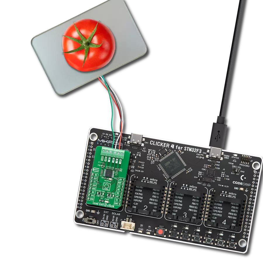
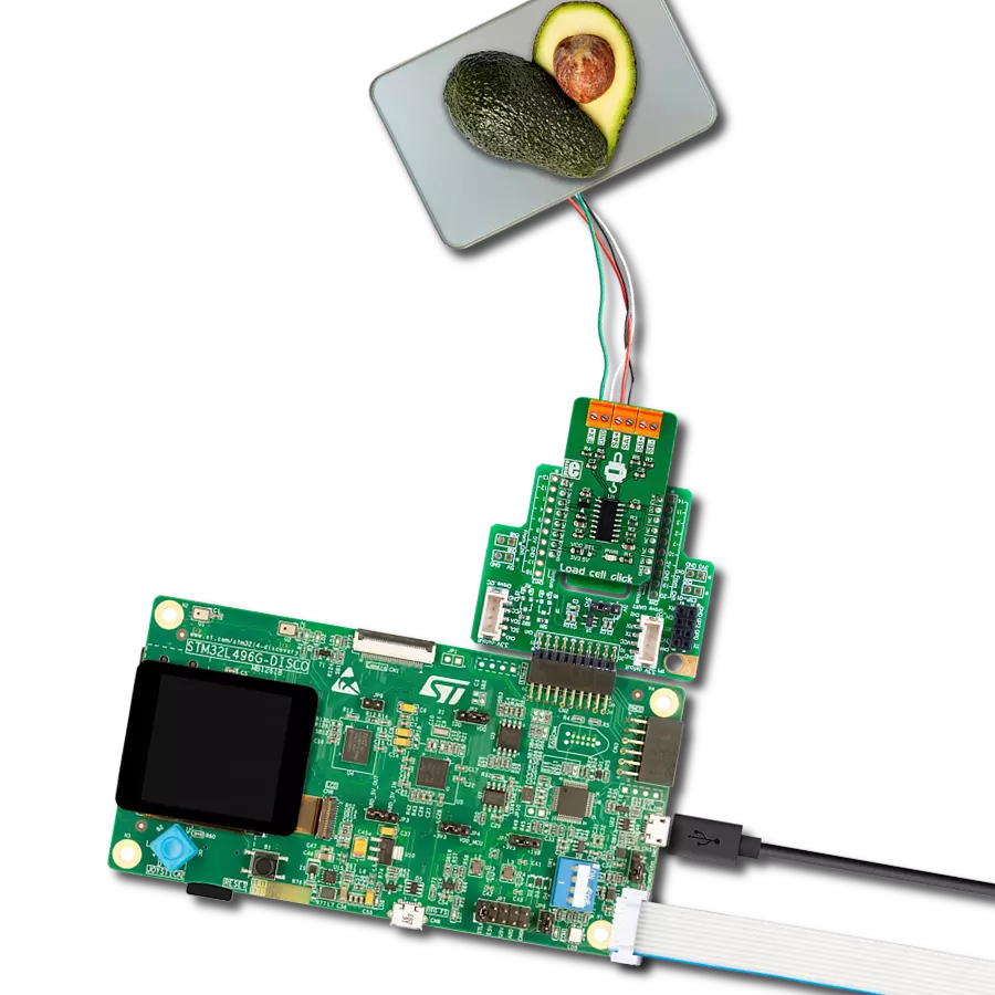
从选择您的开发板和Click板™开始。以Discovery kit with STM32L496AG MCU作为您的开发板开始。


实时跟踪您的结果
应用程序输出
1. 应用程序输出 - 在调试模式下,“应用程序输出”窗口支持实时数据监控,直接提供执行结果的可视化。请按照提供的教程正确配置环境,以确保数据正确显示。

2. UART 终端 - 使用UART Terminal通过USB to UART converter监视数据传输,实现Click board™与开发系统之间的直接通信。请根据项目需求配置波特率和其他串行设置,以确保正常运行。有关分步设置说明,请参考提供的教程。

3. Plot 输出 - Plot功能提供了一种强大的方式来可视化实时传感器数据,使趋势分析、调试和多个数据点的对比变得更加直观。要正确设置,请按照提供的教程,其中包含使用Plot功能显示Click board™读数的分步示例。在代码中使用Plot功能时,请使用以下函数:plot(insert_graph_name, variable_name);。这是一个通用格式,用户需要将“insert_graph_name”替换为实际图表名称,并将“variable_name”替换为要显示的参数。

软件支持
库描述
此库包含 Load Cell Click 驱动程序的 API。
关键功能:
loadcell_read_results- 读取结果功能loadcell_set_rate- 设置速率功能loadcell_check_out- 检查 DO 引脚状态功能loadcell_reset- 重置时钟功能loadcell_set_mode- 归零功能并读取结果loadcell_tare- 归零功能并读取结果loadcell_calibration- 校准功能loadcell_get_weight- 获取重量功能
开源
代码示例
完整的应用程序代码和一个现成的项目可以通过NECTO Studio包管理器直接安装到NECTO Studio。 应用程序代码也可以在MIKROE的GitHub账户中找到。
/*!
 * \file
 * \brief Load cell Click example
 *
 * # Description
 * Load cell Click is a weight measurement Click which utilizes a load cell element,
 * in order to precisely measure the weight of an object.
 * The Load Cell Click can be used with the strain gauge type of load cells
 * and can measure up to ±20V or ±40V of differential voltage.
 *
 * The demo application is composed of two sections :
 *
 * ## Application Init
 * Initializes GPIO driver and performs the device reset,
 * after which the next conversion cycle will be for channel B with 32 gate value.
 * This function also selects the frequency of internal oscillator to 10Hz.
 * Sets tare the scale, calibrate scale and start measurements.
 *
 * ## Application Task
 * This is an example which demonstrates the use of Load Cell Click board.
 * Display the measurement of scales in grams [ g ].
 * Results are being sent to the Usart Terminal where you can track their changes.
 * All data logs write on USB uart changes for every 1 sec.
 *
 * \author MikroE Team
 *
 */
// ------------------------------------------------------------------- INCLUDES

#include "board.h"
#include "log.h"
#include "loadcell.h"

// ------------------------------------------------------------------ VARIABLES

static loadcell_t loadcell;
static log_t logger;

loadcell_data_t cell_data;
static float weight_val;

// ------------------------------------------------------- ADDITIONAL FUNCTIONS


// ------------------------------------------------------ APPLICATION FUNCTIONS

void application_init ( void )
{
    log_cfg_t log_cfg;
    loadcell_cfg_t cfg;

    /**
     * Logger initialization.
     * Default baud rate: 115200
     * Default log level: LOG_LEVEL_DEBUG
     * @note If USB_UART_RX and USB_UART_TX
     * are defined as HAL_PIN_NC, you will
     * need to define them manually for log to work.
     * See @b LOG_MAP_USB_UART macro definition for detailed explanation.
     */
    LOG_MAP_USB_UART( log_cfg );
    log_init( &logger, &log_cfg );
    log_info( &logger, "---- Application Init ----" );

    //  Click initialization.

    loadcell_cfg_setup( &cfg );
    LOADCELL_MAP_MIKROBUS( cfg, MIKROBUS_1 );
    loadcell_init( &loadcell, &cfg );

    log_printf(&logger, "-------------------------\r\n");
    log_printf(&logger, "     Load cell Click     \r\n");
    log_printf(&logger, "-------------------------\r\n");
    Delay_ms ( 100 );

    loadcell_set_mode( &loadcell, LOADCELL_POWER_UP );
    Delay_ms ( 100 );

    loadcell_reset( &loadcell );
    Delay_ms ( 100 );

    loadcell_set_rate( &loadcell, LOADCELL_10HZ_INTERNAL_OSC );
    Delay_ms ( 100 );

    log_printf(&logger, "    Tare the scale :   Channel B,  Gate 32  \r\n");
    log_printf(&logger, "-------------------------\r\n");
    log_printf(&logger, " In the following 10 seconds please REMOVE all object from the scale.\r\n");
    // 10 seconds delay
    Delay_ms ( 1000 );
    Delay_ms ( 1000 );
    Delay_ms ( 1000 );
    Delay_ms ( 1000 );
    Delay_ms ( 1000 );
    Delay_ms ( 1000 );
    Delay_ms ( 1000 );
    Delay_ms ( 1000 );
    Delay_ms ( 1000 );
    Delay_ms ( 1000 );

    log_printf(&logger, "-------------------------\r\n");
    log_printf(&logger, "    Start tare scales    \r\n");
    loadcell_tare ( &loadcell, LOADCELL_CHANN_B_GATE_32_NEXT, &cell_data );
    Delay_ms ( 500 );

    log_printf(&logger, "-------------------------\r\n");
    log_printf(&logger, "    Tarring completed \r\n");

    log_printf(&logger, "-------------------------\r\n");
    log_printf(&logger, " In the following 10 seconds place 100g weight etalon on the scale for calibration purpose.\r\n");
    // 10 seconds delay
    Delay_ms ( 1000 );
    Delay_ms ( 1000 );
    Delay_ms ( 1000 );
    Delay_ms ( 1000 );
    Delay_ms ( 1000 );
    Delay_ms ( 1000 );
    Delay_ms ( 1000 );
    Delay_ms ( 1000 );
    Delay_ms ( 1000 );
    Delay_ms ( 1000 );

    log_printf(&logger, "-------------------------\r\n");
    log_printf(&logger, "    Start calibration    \r\n");

    if ( loadcell_calibration ( &loadcell, LOADCELL_CHANN_B_GATE_32_NEXT, LOADCELL_WEIGHT_100G, &cell_data ) == LOADCELL_GET_RESULT_OK )
    {
        log_printf(&logger, "-------------------------\r\n");
        log_printf(&logger, "    Calibration  Done    \r\n");

        log_printf(&logger, "- - - - - - - - - - - - -\r\n");
        log_printf(&logger, " In the following 10 seconds please REMOVE all object from the scale.\r\n");
        // 10 seconds delay
        Delay_ms ( 1000 );
        Delay_ms ( 1000 );
        Delay_ms ( 1000 );
        Delay_ms ( 1000 );
        Delay_ms ( 1000 );
        Delay_ms ( 1000 );
        Delay_ms ( 1000 );
        Delay_ms ( 1000 );
        Delay_ms ( 1000 );
        Delay_ms ( 1000 );
    }
    else
    {
        log_printf(&logger, "-------------------------\r\n");
        log_printf(&logger, "   Calibration  Error   \r\n");
        for ( ; ; );
    }

    log_printf(&logger, "-------------------------\r\n");
    log_printf(&logger, "   Start measurements :  \r\n");
    log_printf(&logger, "-------------------------\r\n");
}

void application_task ( void )
{
    weight_val = loadcell_get_weight( &loadcell, LOADCELL_CHANN_B_GATE_32_NEXT, &cell_data );

    log_printf(&logger, "     Weight : %.2f\r\n", weight_val );

    Delay_ms ( 1000 );
}

int main ( void )
{
    /* Do not remove this line or clock might not be set correctly. */
    #ifdef PREINIT_SUPPORTED
    preinit();
    #endif

    application_init( );

    for ( ; ; )
    {
        application_task( );
    }

    return 0;
}


// ------------------------------------------------------------------------ END
额外支持
资源
类别:力