使用ISL1221和STM32F302VC让每一刻都变得重要
记录每一刻
已发布 7月 22, 2025
点击板
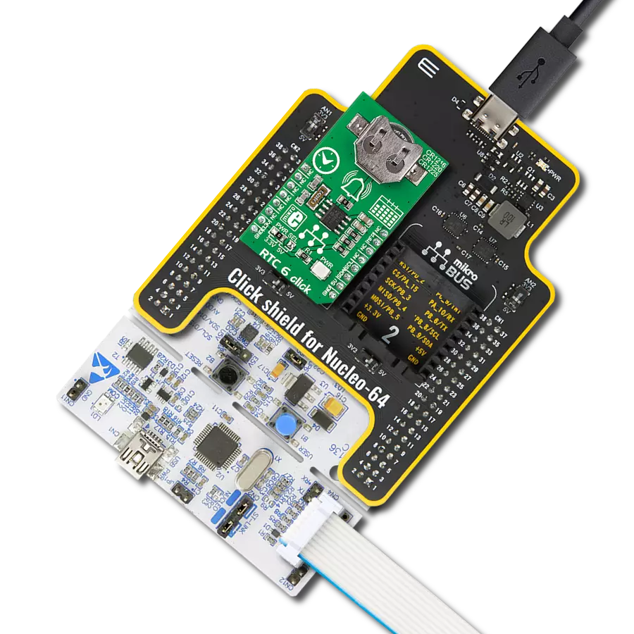
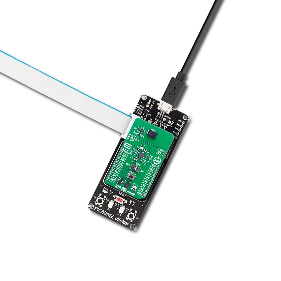
RTC 14 Click
开发板
CLICKER 4 for STM32F302VCT6
编译器
NECTO Studio
微控制器单元
STM32F302VC
利用这一尖端的实时时钟技术,在您的应用程序中实现精确的时间同步。
A
A
硬件概览
它是如何工作的?
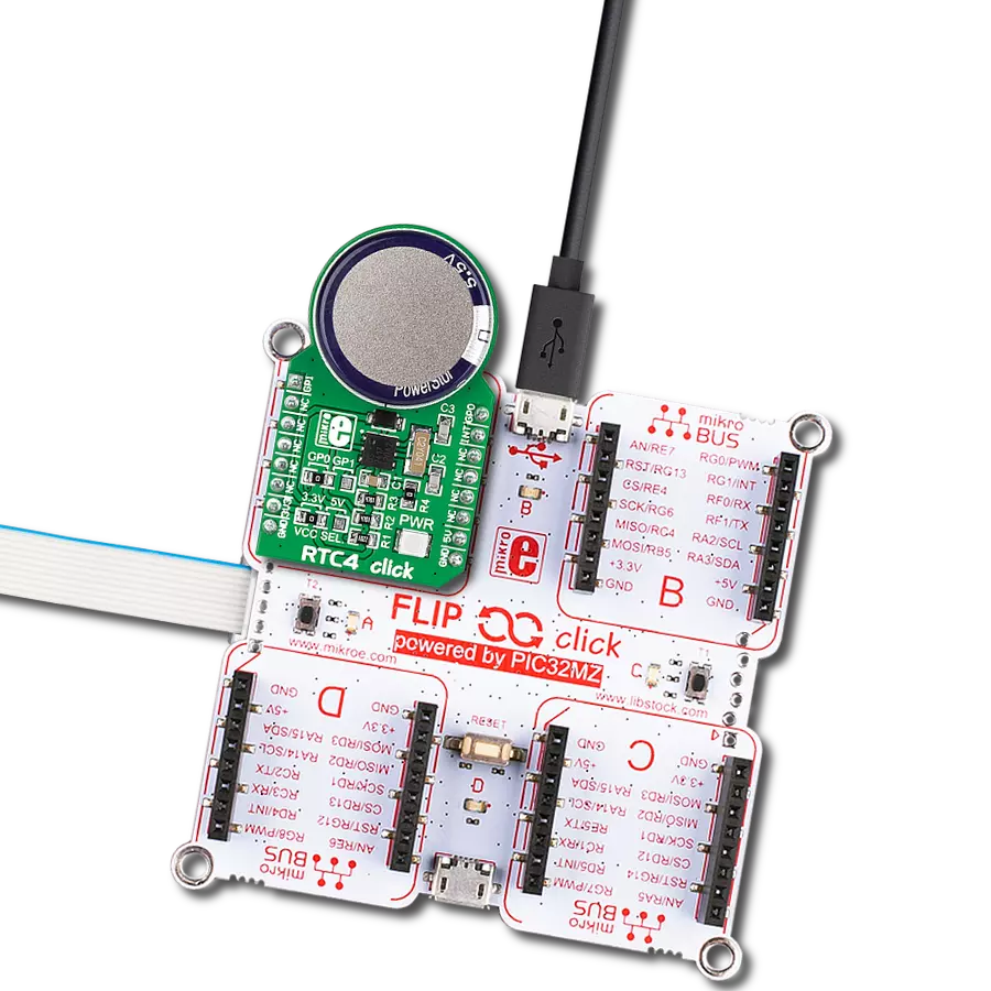
RTC 14 Click基于瑞萨的ISL1221,这是一款小型微功耗实时时钟,提供了增强的安全功能和防篡改检测。该设备在正常模式和电池模式下具有时间戳功能、定时和晶体补偿、时钟/日历、电源故障指示、周期性或轮询闹钟、智能电池备份切换以及电池支持的用户SRAM。由于其增强的安全功能,该RTC非常适用于各种应用,包括安全、保修监测、数据采集、记录和时间戳单个事件,例如安全门的开闭等周期性事件。如前所述,ISL1221可以通过发出包含触发事件发生的秒、分钟、小时、日期、月份和年份的输出信号,或者在事件发生时停止RTC寄存器的增进来对外部事件进行时间戳。该设备还具有用于日期、月份、年份和星期几的日历寄存器,
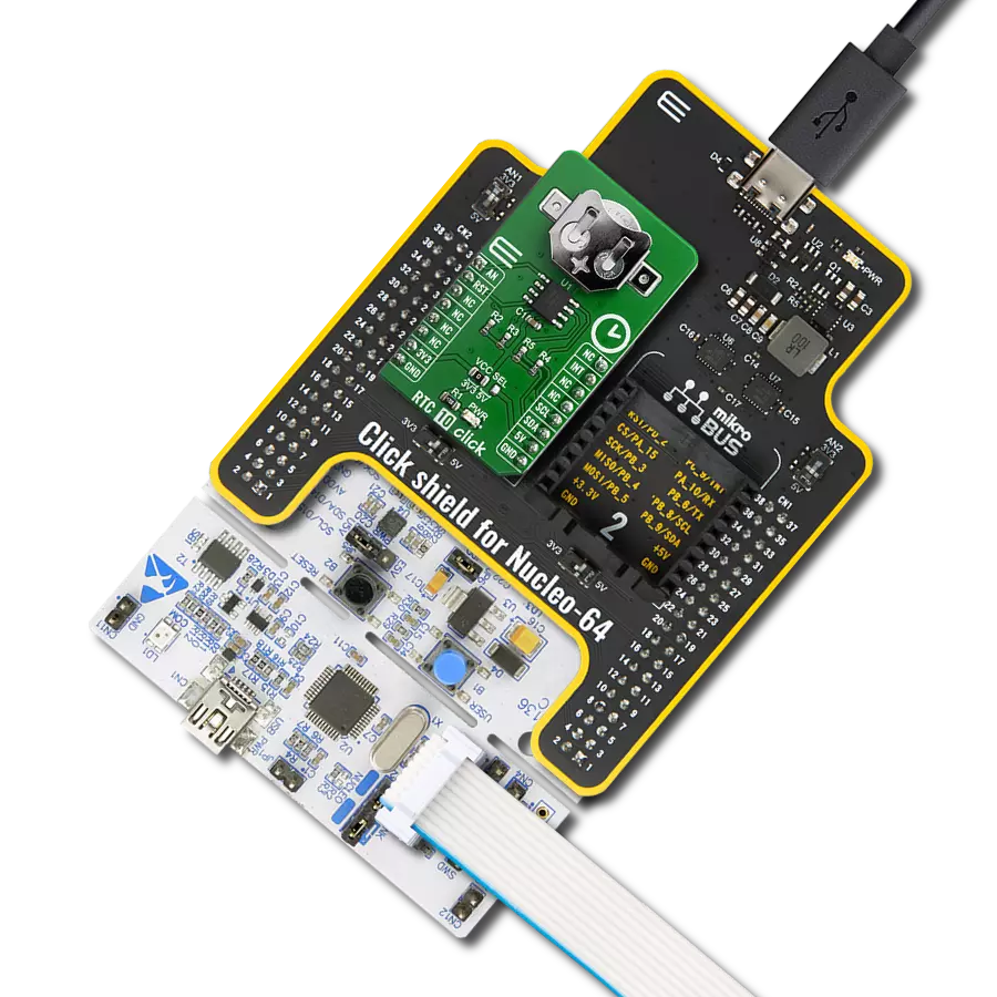
通过2099年之前都非常准确,并且具有自动闰年校正功能。闹钟可以设置为任何时钟/日历值(例如,每分钟、每星期五,或在9:41 AM的9月10日)。可以通过检查状态寄存器或通过路由到mikroBUS™插座的INT引脚的硬件中断引脚获取闹钟状态。闹钟还包含重复模式,允许每分钟、每小时和每天定期中断一次。RTC 14 Click通过标准的I2C 2-Wire接口与MCU通信,以读取数据和配置设置,支持最高达400kHz的快速模式操作。此外,它具有可编程的频率输出,可从32.768kHz到1/32Hz,可在mikroBUS™插座的PWM引脚和标记为FO的板载标头引脚处使用。该功能用于各种定时应用,包括在睡眠模式下为MCU提供时钟,消除外部晶体,并进一步减少
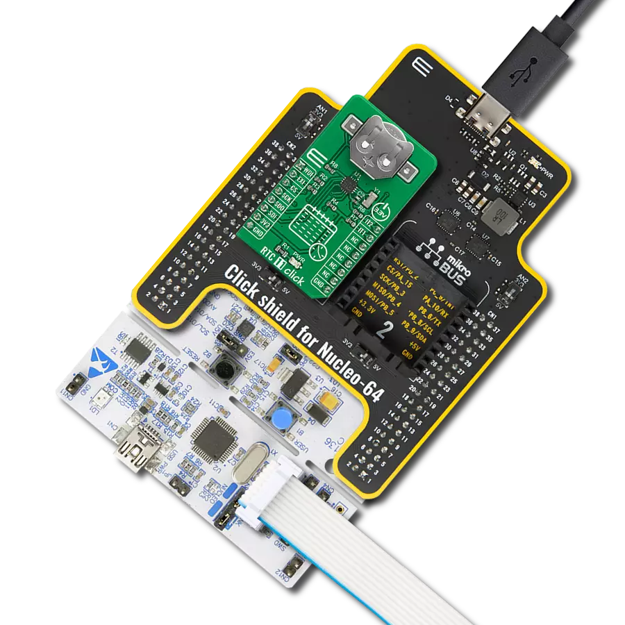
BOM。要使用板载标头上提供的外部事件输入或频率输出等功能,需要填充电阻R8和R9,并因此在标头上激活这些功能。像这样,最常见的RTC配置是备份电池支持的,它可以维持时间并且可以在提供的用于数据存储的2字节备份SRAM中保存数据。因此,除了ISL1221外,RTC 14 Click还具有与3000TR电池座兼容的按钮电池座,适用于12mm硬币电池。此Click board™可以使用通过VCC SEL跳线选择的3.3V或5V逻辑电压级别运行。这样,既可以使用3.3V又可以使用5V的MCU可以正确使用通信线路。此外,此Click board™配备了一个包含易于使用的函数和示例代码的库,可用作进一步开发的参考。

功能概述
开发板
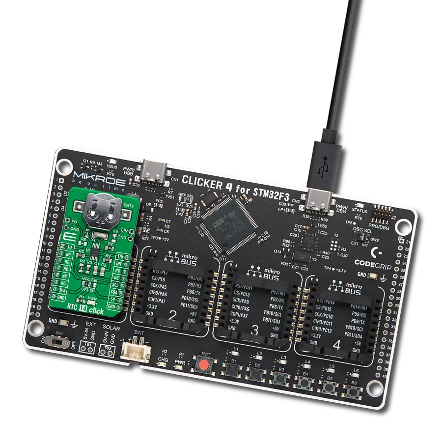
Clicker 4 for STM32F3 是一款紧凑型开发板,作为完整的解决方案而设计,可帮助用户快速构建具备独特功能的定制设备。该板搭载 STMicroelectronics 的 STM32F302VCT6 微控制器,配备四个 mikroBUS™ 插槽用于连接 Click boards™、完善的电源管理功能以及其他实用资源,是快速开发各类应用的理想平台。其核心 MCU STM32F302VCT6 基于高性能
Arm® Cortex®-M4 32 位处理器,运行频率高达 168MHz,处理能力强大,能够满足各种高复杂度任务的需求,使 Clicker 4 能灵活适应多种应用场景。除了两个 1x20 引脚排针外,板载最显著的连接特性是四个增强型 mikroBUS™ 插槽,支持接入数量庞大的 Click boards™ 生态系统,该生态每日持续扩展。Clicker 4 各功能区域标识清晰,界面直观简洁,极大
提升使用便捷性和开发效率。Clicker 4 的价值不仅在于加速原型开发与应用构建阶段,更在于其作为独立完整方案可直接集成至实际项目中,无需额外硬件修改。四角各设有直径 4.2mm(0.165")的安装孔,便于通过螺丝轻松固定。对于多数应用,只需配套一个外壳,即可将 Clicker 4 开发板转化为完整、实用且外观精美的定制系统。

微控制器概述
MCU卡片 / MCU

建筑
ARM Cortex-M4
MCU 内存 (KB)
256
硅供应商
STMicroelectronics
引脚数
100
RAM (字节)
40960
使用的MCU引脚
mikroBUS™映射器
“仔细看看!”
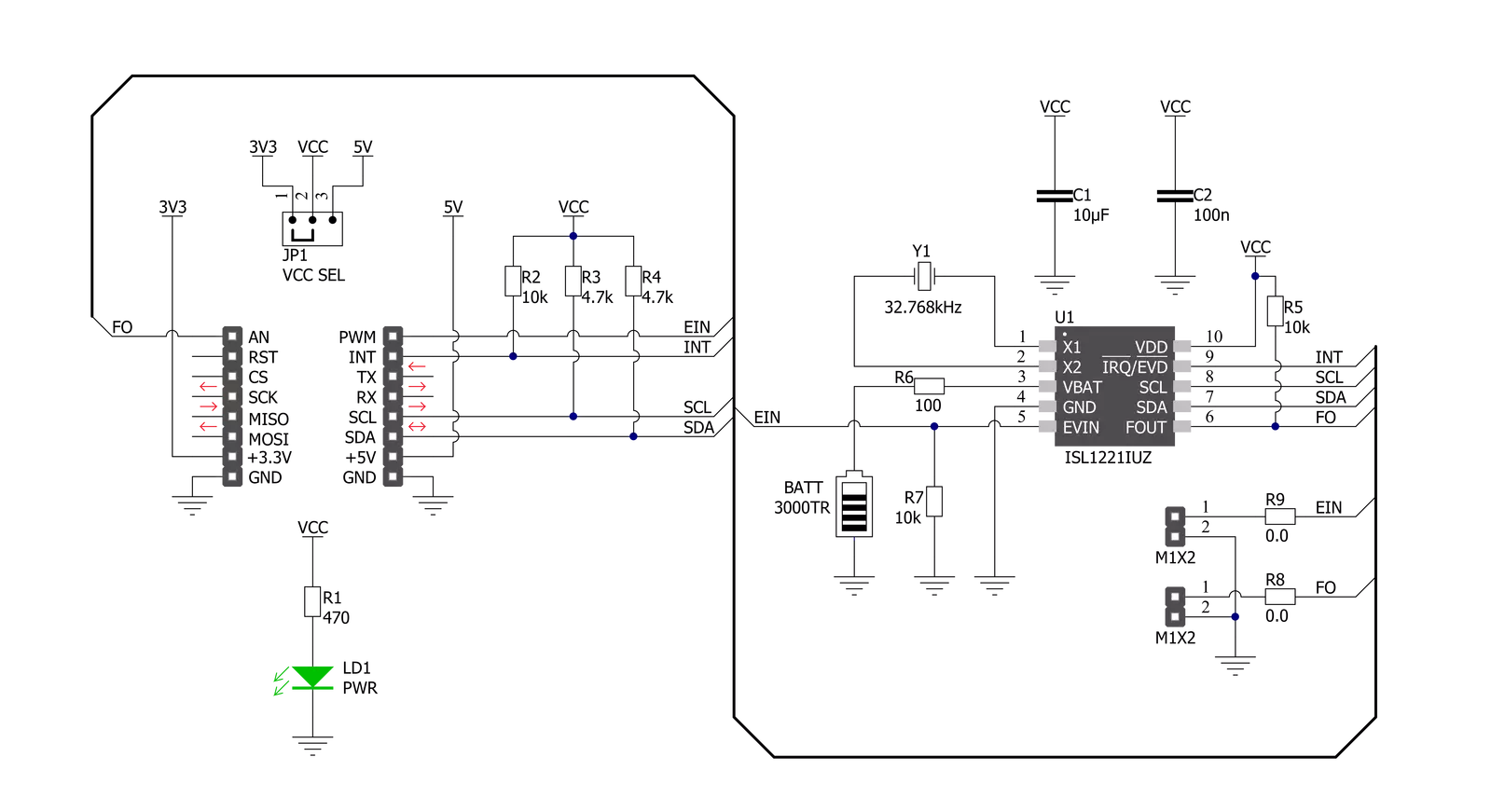
Click board™ 原理图
一步一步来
项目组装

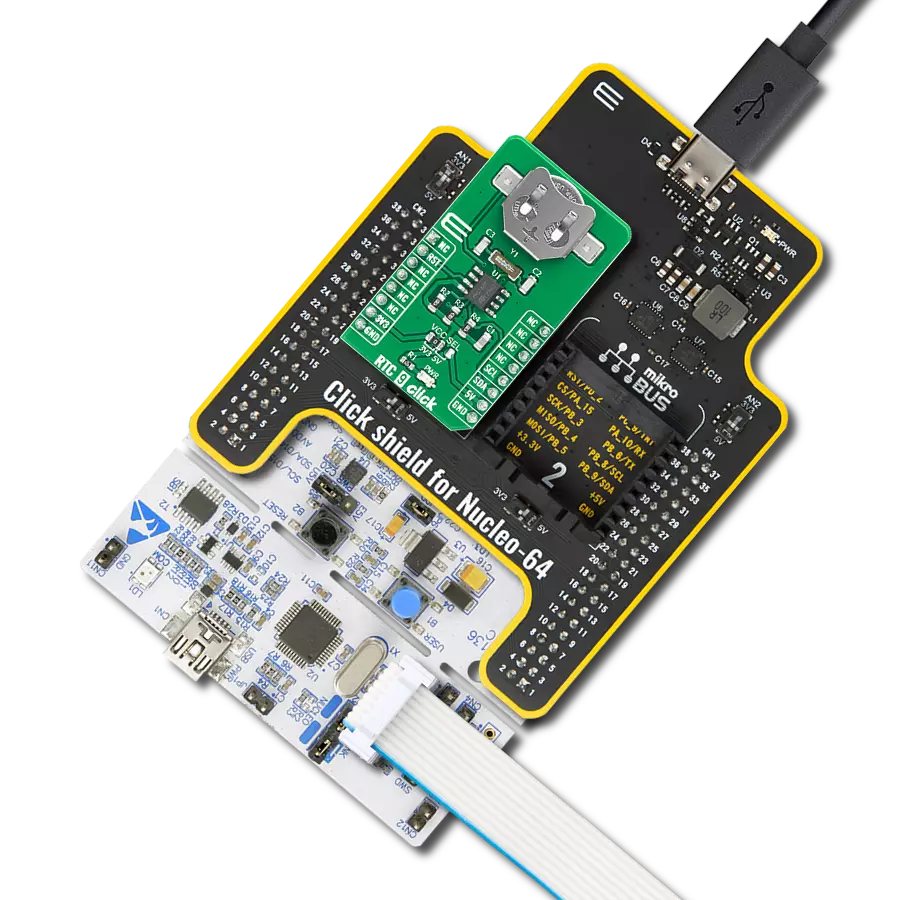
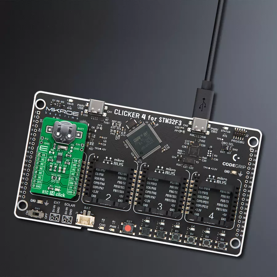
从选择您的开发板和Click板™开始。以CLICKER 4 for STM32F302VCT6作为您的开发板开始。


软件支持
库描述
该库包含 RTC 14 Click 驱动程序的 API。
关键功能:
rtc14_get_time- RTC 14 获取时间函数rtc14_set_time- RTC 14 设置时间函数rtc14_get_date- RTC 14 获取日期函数
开源
代码示例
完整的应用程序代码和一个现成的项目可以通过NECTO Studio包管理器直接安装到NECTO Studio。 应用程序代码也可以在MIKROE的GitHub账户中找到。
/*!
 * @file main.c
 * @brief RTC14 Click example
 *
 * # Description
 * This is an example that demonstrates the use of the RTC 14 Click board™.
 *
 * The demo application is composed of two sections :
 *
 * ## Application Init
 * Initialization of I2C module, log UART and additional pins.
 * After driver initialization and default settings,
 * the app set the time to 11:59:50 PM ( 12-hour format )
 * and set date to Thursday 05.08.2021.
 *
 * ## Application Task
 * This is an example that shows the use of a RTC 14 Click board™.
 * In this example, we read and display the current time ( AM or PM )
 * and date ( day of the week ), which we also previously set.
 * Results are being sent to the Usart Terminal where you can track their changes.
 * All data logs write on USB changes every 1 sec.
 *
 * ## Additional Function
 * - static void display_day_of_week ( void ) - The function displays the day of the week.
 *
 * @author Nenad Filipovic
 *
 */

#include "board.h"
#include "log.h"
#include "rtc14.h"

static rtc14_t rtc14;
static log_t logger;
static uint8_t new_sec = 255;
static rtc14_time_t time;
static rtc14_date_t date;

static void display_day_of_week ( void )
{
    switch ( date.day_of_week )
    {
        case RTC14_DW_SUNDAY:
        {
            log_printf( &logger, "Su\r\n" );
            break;
        }
        case RTC14_DW_MONDAY:
        {
            log_printf( &logger, "Mo\r\n" );
            break;
        }
        case RTC14_DW_TUESDAY:
        {
            log_printf( &logger, "Tu\r\n" );
            break;
        }
        case RTC14_DW_WEDNESDAY:
        {
            log_printf( &logger, "We\r\n" );
            break;
        }
        case RTC14_DW_THURSDAY:
        {
            log_printf( &logger, "Th\r\n" );
            break;
        }
        case RTC14_DW_FRIDAY:
        {
            log_printf( &logger, "Fr\r\n" );
            break;
        }
        case RTC14_DW_SATURDAY:
        {
            log_printf( &logger, "Sa\r\n" );
            break;
        }
    }
}

void application_init ( void )
{
    log_cfg_t log_cfg;      /**< Logger config object. */
    rtc14_cfg_t rtc14_cfg;  /**< Click config object. */

    /**
     * Logger initialization.
     * Default baud rate: 115200
     * Default log level: LOG_LEVEL_DEBUG
     * @note If USB_UART_RX and USB_UART_TX
     * are defined as HAL_PIN_NC, you will
     * need to define them manually for log to work.
     * See @b LOG_MAP_USB_UART macro definition for detailed explanation.
     */
    LOG_MAP_USB_UART( log_cfg );
    log_init( &logger, &log_cfg );
    log_info( &logger, " Application Init " );

    // Click initialization.
    rtc14_cfg_setup( &rtc14_cfg );
    RTC14_MAP_MIKROBUS( rtc14_cfg, MIKROBUS_1 );
    err_t init_flag = rtc14_init( &rtc14, &rtc14_cfg );
    if ( I2C_MASTER_ERROR == init_flag )
    {
        log_error( &logger, " Application Init Error. " );
        log_info( &logger, " Please, run program again... " );

        for ( ; ; );
    }

    rtc14_default_cfg ( &rtc14 );
    Delay_ms ( 100 );

    time.hours_format = RTC14_SET_HOURS_FORMAT_12;
    time.am_pm = RTC14_SET_HOURS_FORMAT_12_PM;
    time.hours = 11;
    time.min = 59;
    time.sec = 50;
    rtc14_set_time( &rtc14, time );
    Delay_ms ( 100 );

    date.day_of_week = RTC14_DW_THURSDAY;
    date.day = 5;
    date.month = 8;
    date.year = 21;
    rtc14_set_date( &rtc14, date );
    Delay_ms ( 100 );

    log_info( &logger, " Application Task " );
    log_printf( &logger, "- - - - - - - - - - -\r\n" );
}

void application_task ( void )
{
    rtc14_get_time( &rtc14, &time );
    Delay_ms ( 1 );
    rtc14_get_date( &rtc14, &date );
    Delay_ms ( 1 );

    if ( time.sec != new_sec )
    {
        log_printf( &logger, "  Date : %.2d-%.2d-%.2d ", ( uint16_t ) date.day, ( uint16_t ) date.month, ( uint16_t ) date.year );
        display_day_of_week( );
        log_printf( &logger, "  Time : %.2d:%.2d:%.2d ", ( uint16_t ) time.hours, ( uint16_t ) time.min, ( uint16_t ) time.sec );
        log_printf( &logger, "%cM\r\n", ( time.am_pm == RTC14_SET_HOURS_FORMAT_12_PM ? 'P' : 'A' ) );
        log_printf( &logger, "- - - - - - - - - - -\r\n" );
        new_sec = time.sec;
        Delay_ms ( 1 );
    }
}

int main ( void )
{
    /* Do not remove this line or clock might not be set correctly. */
    #ifdef PREINIT_SUPPORTED
    preinit();
    #endif

    application_init( );

    for ( ; ; )
    {
        application_task( );
    }

    return 0;
}

// ------------------------------------------------------------------------ END
额外支持
资源
类别:实时时钟