使用LDC1312-Q1和PIC32MZ2048EFM100将电感测量转化为数字数据
您的电感到数字转换器!
已发布 7月 22, 2025
点击板
LDC Click
开发板
Curiosity PIC32 MZ EF
编译器
NECTO Studio
微控制器单元
PIC32MZ2048EFM100
解锁无限可能性,借助我们的电感-数字奇迹,将电感值轻松转换为数字数据,使其成为实时监测、质量控制和系统自动化的重要组成部分。
A
A
硬件概览
它是如何工作的?
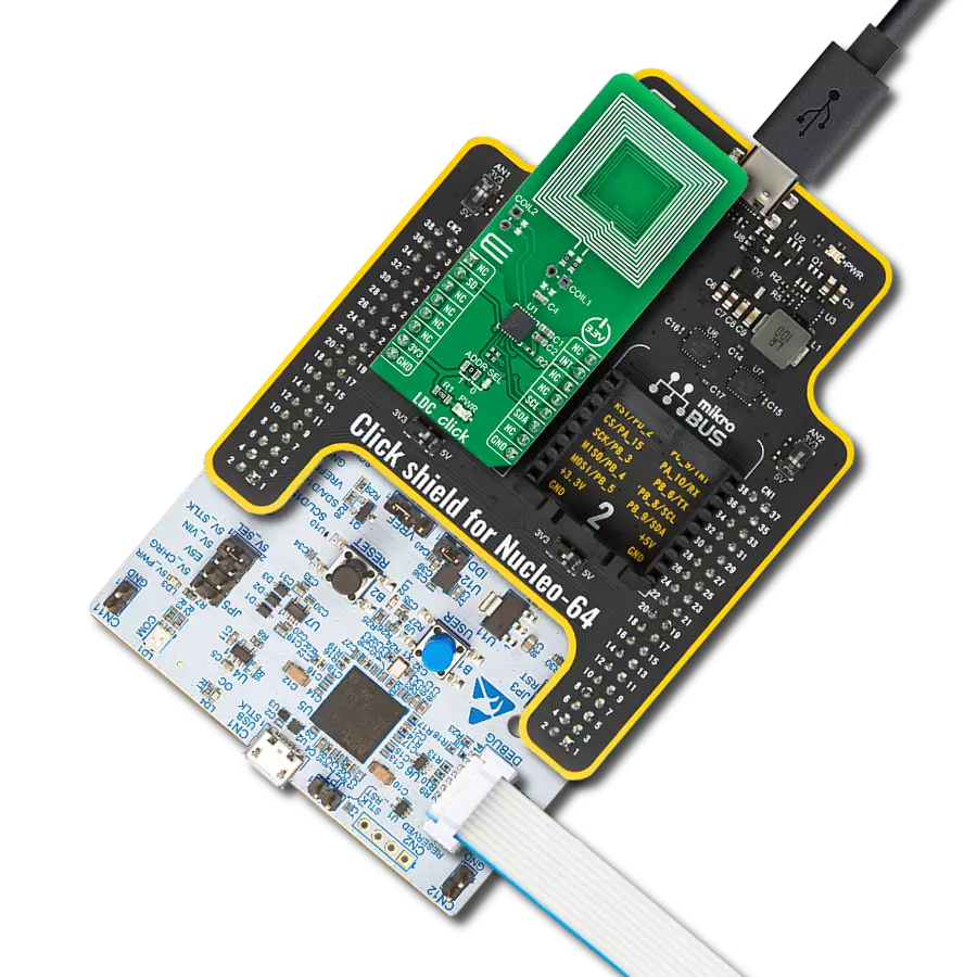
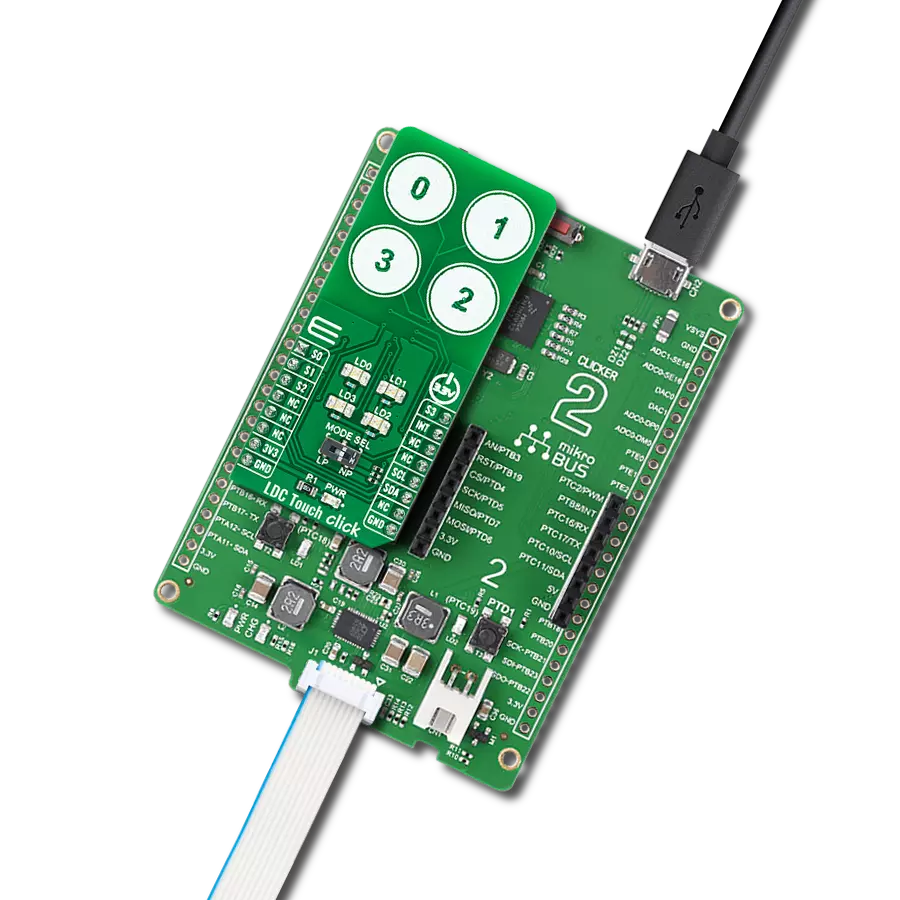
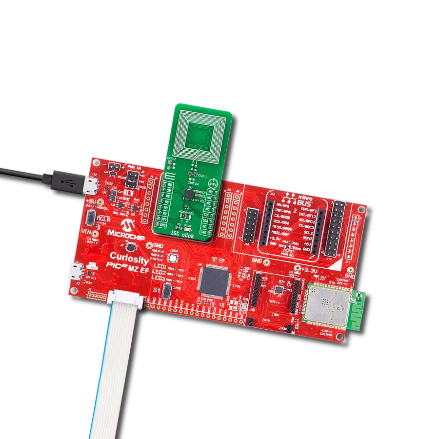
LDC Click基于德州仪器的LDC1312-Q1,这是一款双通道、12位电感到数字转换器(LDCs),用于电感传感解决方案。这个Click board™易于使用,只需要在1kHz和10MHz之间的传感器频率即可开始传感。它测量LC谐振器的振荡频率,并输出与频率成比例的数字值。电感传感在低成本和功耗下提供了比竞争技术更好的性能、可靠性和灵活性。该板适用于对导电目标的位置、运动或组成进行精确的短程测量。与交流电磁(EM)场接触的导电物体会引起场变化,可以使用感应器(如电感器)来检测这些变化。方便地,电感器和电容
器用于构建LC谐振器,也称为LC谐振器,以产生EM场。在LC谐振器的情况下,场扰动的效果是传感器的电感的明显变化,这可以观察为谐振频率的变化-使用这个原理,LDC1312-Q1工作。LDC Click使用标准的I2C 2-Wire接口与MCU通信,最大时钟频率为400kHz。除了I2C通信外,还使用了连接到mikroBUS™插座引脚的两个GPIO引脚。连接到mikroBUS™插座的RST引脚的SD引脚用于将LDC1312-Q1置于关断模式,节省电流,而INT引脚可以配置为中断,以通知主机MCU系统状态的变化。此外,它还允许通过将标记为ADDR
SEL的SMD跳线器放置在标记为1和0的适当位置来选择其I2C从机地址的最低有效位。它还可以连接额外的外部LC传感器,允许您替换提供的板载传感器,并在标记为COIL1和COIL2的位置焊接您自己的传感器。此Click board™只能在3.3V逻辑电压电平下操作。在使用具有不同逻辑电平的MCU之前,板必须执行适当的逻辑电压电平转换。此外,它配备了一个包含易于使用的功能和示例代码的库,可用作进一步开发的参考。


功能概述
开发板
Curiosity PIC32 MZ EF 开发板是一个完全集成的 32 位开发平台,特点是高性能的 PIC32MZ EF 系列(PIC32MZ2048EFM),该系列具有 2MB Flash、512KB RAM、集成的浮点单元(FPU)、加密加速器和出色的连接选项。它包括一个集成的程序员和调试器,无需额外硬件。用户可以通过 MIKROE
mikroBUS™ Click™ 适配器板扩展功能,通过 Microchip PHY 女儿板添加以太网连接功能,使用 Microchip 扩展板添加 WiFi 连接能力,并通过 Microchip 音频女儿板添加音频输入和输出功能。这些板完全集成到 PIC32 强大的软件框架 MPLAB Harmony 中,该框架提供了一个灵活且模块化的接口
来应用开发、一套丰富的互操作软件堆栈(TCP-IP、USB)和易于使用的功能。Curiosity PIC32 MZ EF 开发板提供了扩展能力,使其成为连接性、物联网和通用应用中快速原型设计的绝佳选择。

微控制器概述
MCU卡片 / MCU

建筑
PIC32
MCU 内存 (KB)
2048
硅供应商
Microchip
引脚数
100
RAM (字节)
524288
使用的MCU引脚
mikroBUS™映射器
“仔细看看!”
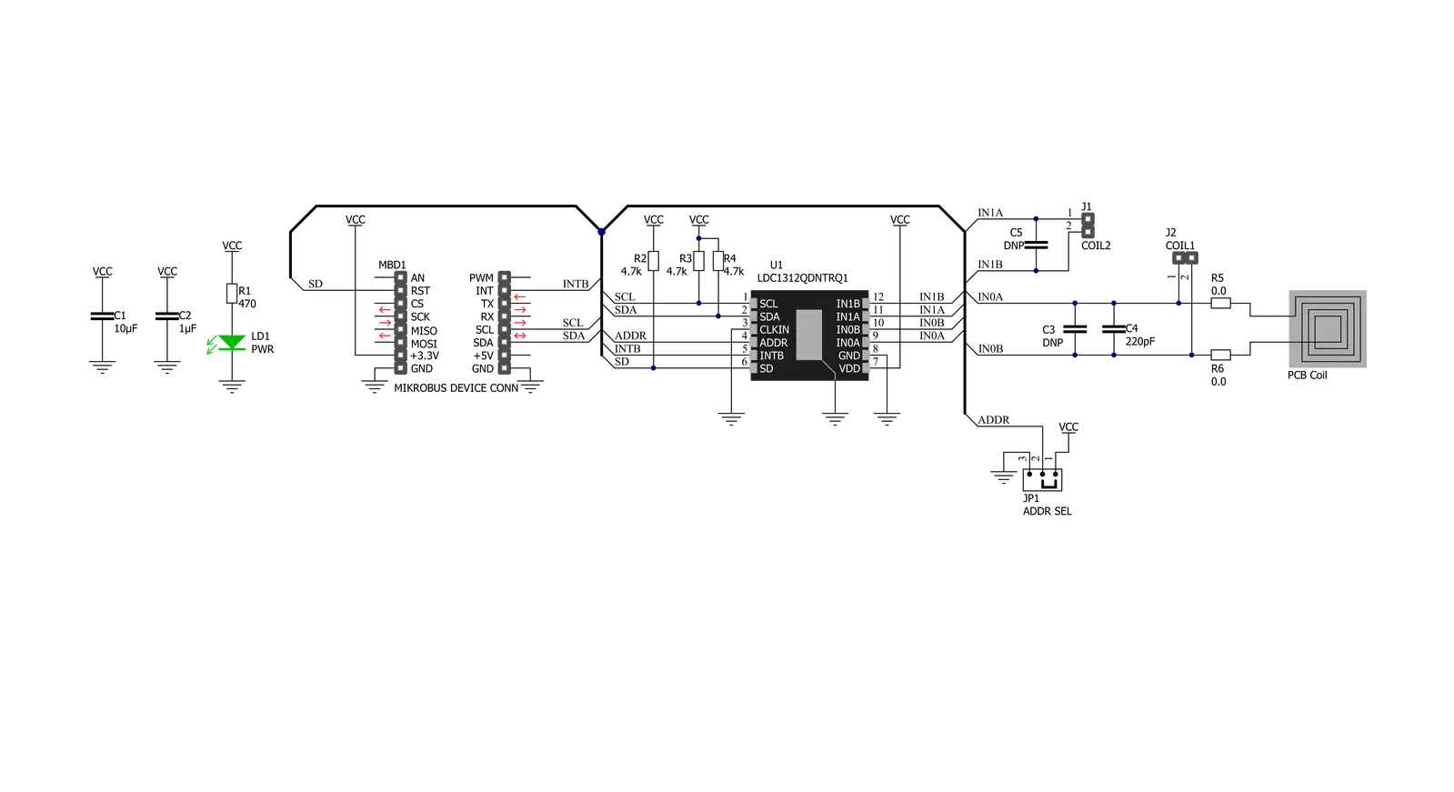
Click board™ 原理图
一步一步来
项目组装

从选择您的开发板和Click板™开始。以Curiosity PIC32 MZ EF作为您的开发板开始。


软件支持
库描述
该库包含 LDC Click 驱动程序的 API。
关键功能:
ldc_get_interrupt- 获取中断引脚状态ldc_get_frequency- 获取特定通道计算的频率值ldc_calculate_inductance- 计算相对于频率的电感值
开源
代码示例
完整的应用程序代码和一个现成的项目可以通过NECTO Studio包管理器直接安装到NECTO Studio。 应用程序代码也可以在MIKROE的GitHub账户中找到。
/*!
 * @file main.c
 * @brief LDC Click example
 *
 * # Description
 * This example showcases the ability of the device to detect
 * metal objects. It configures a device for reading data from
 * channel 0, checks if ID's are OK and reads data when interrupting
 * is asserted and logs result.
 *
 * The demo application is composed of two sections :
 *
 * ## Application Init
 * Initialization of communication modules (I2C, UART) and
 * additional pins. Then configures the device for reading data from
 * channel 0, and checks if device ID's are correctly read, and
 * read the currently set divider.
 *
 * ## Application Task
 * Checks if interrupt pin is asserted, if so reads data from channel 0.
 * Calculates and returns the frequency of the sensor. If the frequency
 * is greater than 0, then it calculates the inductance of the sensor.
 * It will log error and error values if it occurred.
 *
 * @author Luka Filipovic
 *
 */

#include "board.h"
#include "log.h"
#include "ldc.h"
#include "math.h"

static ldc_t ldc;
static log_t logger;

uint16_t divider;

void application_init ( void )
{
    log_cfg_t log_cfg;  /**< Logger config object. */
    ldc_cfg_t ldc_cfg;  /**< Click config object. */

    /**
     * Logger initialization.
     * Default baud rate: 115200
     * Default log level: LOG_LEVEL_DEBUG
     * @note If USB_UART_RX and USB_UART_TX
     * are defined as HAL_PIN_NC, you will
     * need to define them manually for log to work.
     * See @b LOG_MAP_USB_UART macro definition for detailed explanation.
     */
    LOG_MAP_USB_UART( log_cfg );
    log_init( &logger, &log_cfg );
    log_info( &logger, " Application Init " );

    // Click initialization.
    ldc_cfg_setup( &ldc_cfg );
    LDC_MAP_MIKROBUS( ldc_cfg, MIKROBUS_1 );
    err_t init_flag = ldc_init( &ldc, &ldc_cfg );
    if ( I2C_MASTER_ERROR == init_flag )
    {
        log_error( &logger, " Application Init Error. " );
        log_info( &logger, " Please, run program again... " );
        for ( ; ; );
    }

    if ( ldc_default_cfg ( &ldc ) < 0 )
    {
        log_error( &logger, " Default configuration. " );
        for ( ; ; );
    }

    uint16_t temp_data = 0;
    ldc_generic_read( &ldc, LDC_REG_MANUFACTURER_ID, &temp_data );
    log_printf( &logger, "> Manufacturer ID: 0x%.4X\r\n", temp_data );
    if ( LDC_MANUFACTURER_ID != temp_data )
    {
        log_error( &logger, " Manufacturer ID. " );
        for ( ; ; );
    }

    ldc_generic_read( &ldc, LDC_REG_DEVICE_ID, &temp_data );
    log_printf( &logger, "> Device ID 0x%.4X\r\n", temp_data );
    if ( LDC_DEVICE_ID != temp_data )
    {
        log_error( &logger, " Device ID. " );
        for ( ; ; );
    }

    ldc_generic_read( &ldc, LDC_REG_CLOCK_DIVIDERS_CH0, &temp_data );
    divider = temp_data & 0x3FF;

    log_info( &logger, " Application Task " );
}

void application_task ( void )
{
    if ( !ldc_get_interrupt( &ldc ) )
    {
        float frequency = 0.0;
        float inductance = 0.0;
        uint16_t status = 0;
        ldc_generic_read( &ldc, LDC_REG_STATUS, &status );
        if ( status & LDC_STATUS_DRDY )
        {
            err_t ret_val = ldc_get_frequency( &ldc, LDC_REG_DATA_CH0, divider, &frequency );
            if ( !ret_val )
            {
                log_printf( &logger, "> Freq[MHz]: %.3f\r\n", frequency );
                if ( frequency > 0 )
                {
                    inductance = ldc_calculate_inductance( frequency );
                }
                log_printf( &logger, "> L[uH]: %.3f\r\n", inductance );
                log_printf( &logger, "> ************************\r\n" );

                Delay_ms ( 500 );
            }
            else
            {
                log_error( &logger, " Reading data: %ld", ret_val );
            }
        }
    }
}

int main ( void )
{
    /* Do not remove this line or clock might not be set correctly. */
    #ifdef PREINIT_SUPPORTED
    preinit();
    #endif

    application_init( );

    for ( ; ; )
    {
        application_task( );
    }

    return 0;
}

// ------------------------------------------------------------------------ END