使用SC18IS602B和STM32F302VC在接口之间建立安全连接
I2C遇见SPI:革命性的接口桥接解决方案!
已发布 7月 22, 2025
点击板
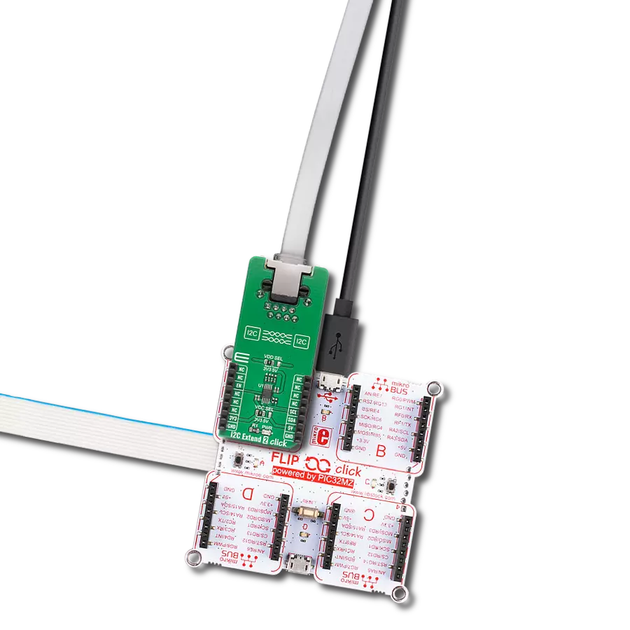
I2C to SPI Click
开发板
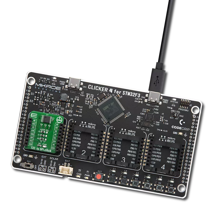
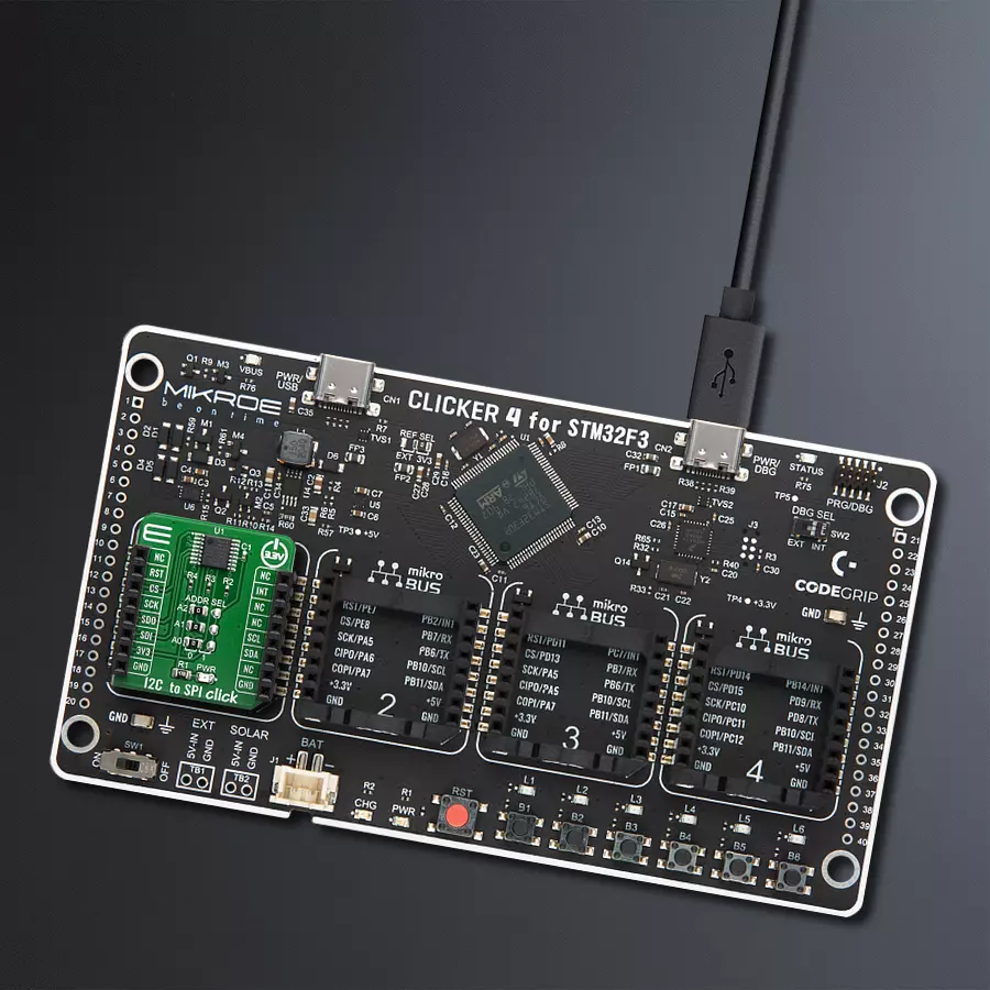
CLICKER 4 for STM32F302VCT6
编译器
NECTO Studio
微控制器单元
STM32F302VC
通过我们的桥接技术,将您的项目提升到接口精度的新高度。它能够弥合I2C和SPI之间的差距,优化数据交换,减少复杂性,并增强您电子应用中的兼容性。
A
A
硬件概览
它是如何工作的?
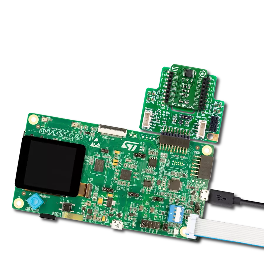
I2C to SPI Click基于两个NXP Semiconductor的SC18IS602B,这是一个I2C总线到SPI桥接器。该IC桥接了两种接口之间的数据通信,提供了许多附加功能,如可编程I/O、内部振荡器选项、低电平有效中断输出、低功耗模式等。SC18IS602B作为I2C总线的从机发送器或从机接收器以及SPI主机操作。SC18IS602B控制所有SPI总线特定的序列、协议和定时。它还具有自己的内部振荡器,并支持SPI芯片选择输出,在未使用时可配置为GPIO。这使得软件易于编写或从其他平台移植。I2C to SPI Click提供面向字节的I2C总线接口,支持高达400 kHz的数据传输。当I2C总线主机从Click板™读取数据时,该设备将是从机发送器。当I2C总线主机发送数据时,它也可以是从机接收器。SC18IS602B在任何时候都不会作
为I2C总线主机操作。然而,它确实具有在字节之间保持SCL线为低电平的能力,以完成其内部过程。SC18IS602B的从机地址由固定部分和可编程部分组成。从机地址的可编程部分使得尽可能多的此类设备能够连接到I2C总线上。由于SC18IS602B具有三个可编程地址位(由A2、A1和A0引脚定义),因此在同一总线上最多可以有八个此类设备。因此,该Click板™配备了三个SMD跳线,归类在ADDR SEL标签下,用于选择I2C从机地址。通过将跳线移动到所需位置,用户可以选择用于与主机MCU通信的地址。#RESET引脚执行SC18IS602B IC的硬件复位。#RESET引脚连接到mikroBUS™的RST引脚,并且为低电平有效。#INT允许主机MCU从SC18IS602B IC接收中断。在完成任何SPI传输后,
SC18IS602B生成中断。因此,SC18IS602B的#INT连接到mikroBUS™插座的INT引脚。可以通过发送“清除中断”命令来清除中断(INT引脚为高电平),尽管这不是必需的。这允许编写更优化的软件(固件),因为主机MCU不必连续轮询LSR寄存器以查看是否需要服务任何中断。SC18IS602B的数据手册提供了有关使用和配置SC18IS602B IC的更多信息。然而,Click板™由mikroSDK库支持,提供简化原型设计和固件开发的功能。该Click板™只能在3.3V逻辑电压水平下运行。在使用具有不同逻辑电平的MCU之前,必须进行适当的逻辑电压电平转换。此外,它配备了一个库,包含函数和示例代码,可用作进一步开发的参考。


功能概述
开发板
Clicker 4 for STM32F3 是一款紧凑型开发板,作为完整的解决方案而设计,可帮助用户快速构建具备独特功能的定制设备。该板搭载 STMicroelectronics 的 STM32F302VCT6 微控制器,配备四个 mikroBUS™ 插槽用于连接 Click boards™、完善的电源管理功能以及其他实用资源,是快速开发各类应用的理想平台。其核心 MCU STM32F302VCT6 基于高性能
Arm® Cortex®-M4 32 位处理器,运行频率高达 168MHz,处理能力强大,能够满足各种高复杂度任务的需求,使 Clicker 4 能灵活适应多种应用场景。除了两个 1x20 引脚排针外,板载最显著的连接特性是四个增强型 mikroBUS™ 插槽,支持接入数量庞大的 Click boards™ 生态系统,该生态每日持续扩展。Clicker 4 各功能区域标识清晰,界面直观简洁,极大
提升使用便捷性和开发效率。Clicker 4 的价值不仅在于加速原型开发与应用构建阶段,更在于其作为独立完整方案可直接集成至实际项目中,无需额外硬件修改。四角各设有直径 4.2mm(0.165")的安装孔,便于通过螺丝轻松固定。对于多数应用,只需配套一个外壳,即可将 Clicker 4 开发板转化为完整、实用且外观精美的定制系统。

微控制器概述
MCU卡片 / MCU

建筑
ARM Cortex-M4
MCU 内存 (KB)
256
硅供应商
STMicroelectronics
引脚数
100
RAM (字节)
40960
使用的MCU引脚
mikroBUS™映射器
“仔细看看!”
Click board™ 原理图

一步一步来
项目组装

从选择您的开发板和Click板™开始。以CLICKER 4 for STM32F302VCT6作为您的开发板开始。


软件支持
库描述
此库包含I2C to SPI Click驱动程序的API。
关键功能:
i2ctospi_spi_write_byte- 此功能通过SPI将数据字节写入I2C to SPI Click上的SC18IS602B I2C总线到SPI桥接器的目标8位寄存器地址。i2ctospi_spi_read_byte- 此功能通过SPI从I2C to SPI Click上的SC18IS602B I2C总线到SPI桥接器的目标8位寄存器地址读取数据字节。i2ctospi_clear_interrupt- 此功能在完成任何SPI传输后清除由SC18IS602B生成的中断。
开源
代码示例
完整的应用程序代码和一个现成的项目可以通过NECTO Studio包管理器直接安装到NECTO Studio。 应用程序代码也可以在MIKROE的GitHub账户中找到。
/*!
 * \file
 * \brief I2cToSpi Click example
 *
 * # Description
 * I2C to SPi Click allows serving as an interface between a standard I2C-bus of a microcontroller
 * and an SPi bus, which allows the microcontroller to communicate directly with SPi devices
 * through its I2C-bus. By offering an I2C-bus slave-transmitter or slave-receiver and SPI master,
 * this Click controls all the SPi bus-specific sequences, protocol, and timing. It also has its own
 * internal oscillator, and it supports the SPi chip select output that may be configured as GPIO when not used.
 *
 * The demo application is composed of two sections :
 *
 * ## Application Init
 * Initialization driver enable's - I2C,
 * hardware reset, SS0 ( CS ) configured to be used as slave select outputs, set the configuration of SPI:
 * order MSB first, clock Idle low, leading-edge transition, SPI clock rate to 115kHz,
 * set SPI EEPROM write enable SS0, clear  interrupt,
 * clear RT5 register, sets starting time: hours, minutes and seconds ( enable counting ), also write log.
 *
 * ## Application Task
 * This is an example which demonstrates the use of RTC 5 Click is wired to I2C to SPI Click board.
 * I2C to SPI Click communicates with register via the I2C interface,
 * serve as an interface between a standard I2C-bus of a microcontroller and an SPI bus.
 * RTC 5 Click communicates with register via SPI interface.
 * In this examples, we display RTC time which we received reading from the target register
 * address of MCP79510 chip on RTC 5 Click board via I2C interface of I2C to SPI Click board.
 * Results are being sent to the Usart Terminal where you can track their changes.
 * All data logs write on usb uart changes for every 1 sec.
 *
 * *note:*
 * <pre>
 * Additional Functions :
 *  - void display_log_uart( uint8_t value ) - Write the value of time or date as a two-digit number.
 *  - void rtc5_clear( i2ctospi_t *ctx, i2ctospi_spi_t *spi ) - Clear RTCC and SRAM memory of RTC 5 Click.
 *  - void rtc5_set_time_seconds( i2ctospi_t *ctx, i2ctospi_spi_t *spi, uint8_t seconds ) - Set the seconds and enable counting.
 *  - uint8_t rtc5_get_time_seconds( i2ctospi_t *ctx, i2ctospi_spi_t *spi ) - Get the seconds.
 *  - void rtc5_set_time_minutes( uint8_t minutes ) - Set the minutes.
 *  - uint8_t rtc5_get_time_minutes( i2ctospi_t *ctx, i2ctospi_spi_t *spi ) - Get the minutes.
 *  - void rtc5_set_time_hours( i2ctospi_t *ctx, i2ctospi_spi_t *spi, uint8_t hours ) - Set the hours.
 *  - uint8_t rtc5_get_time_hours( i2ctospi_t *ctx, i2ctospi_spi_t *spi ) - Get the hours.
 * </pre>
 *
 * \author MikroE Team
 *
 */
// ------------------------------------------------------------------- INCLUDES

#include "board.h"
#include "log.h"
#include "i2ctospi.h"

// ------------------------------------------------------------------ VARIABLES

static i2ctospi_t i2ctospi;
static i2ctospi_spi_t i2ctospi_spi;
static i2ctospi_gpio_t i2ctospi_gpio;
static log_t logger;

static uint8_t time_hours;
static uint8_t time_minutes;
static uint8_t time_seconds;
static uint8_t time_seconds_new = 0xFF;

// ------------------------------------------------------- ADDITIONAL FUNCTIONS

void display_log_uart ( uint8_t value )
{
    log_printf( &logger, " %d%d ", ( uint16_t )( value / 10 ), ( uint16_t )( value % 10 ) );
}

void rtc5_clear ( i2ctospi_t *ctx, i2ctospi_spi_t *spi )
{
    uint8_t reg_add;

    spi->slave_device = I2CTOSPI_SLAVEDEVICE_SS0;
    spi->function_id = I2CTOSPI_RTC5_COMMAND_WRITE;
    spi->reg_addr = reg_add;

    for ( reg_add = 0; reg_add < 0x20; reg_add++ )
    {
        i2ctospi_spi_write_byte( ctx, spi, 0x00 );
        Delay_1us( );
    }

    spi->reg_addr = I2CTOSPI_RTC5_COMMAND_CLEAR;
    i2ctospi_spi_write_byte( ctx, spi, 0x00 );

    i2ctospi_clear_interrupt( ctx );
}

void rtc5_set_time_seconds ( i2ctospi_t *ctx, i2ctospi_spi_t *spi, uint8_t seconds )
{
    uint8_t ones;
    uint8_t tens;
    uint8_t temp;

    ones = 0x00;
    tens = 0x00;

    seconds %= 60;

    ones = seconds % 10;

    tens = ( seconds / 10 ) << 4;

    temp = tens | ones;
    temp |= I2CTOSPI_RTC5_COMMAND_ENABLE_COUNTING;

    spi->slave_device = I2CTOSPI_SLAVEDEVICE_SS0;
    spi->function_id = I2CTOSPI_RTC5_COMMAND_WRITE;
    spi->reg_addr = I2CTOSPI_RTC5_REG_TIME_SEC;

    i2ctospi_spi_write_byte( ctx, spi, temp );
}

uint8_t rtc5_get_time_seconds ( i2ctospi_t *ctx, i2ctospi_spi_t *spi )
{
    uint8_t ones;
    uint8_t tens;
    uint8_t result_sec;
    uint8_t temp;

    spi->slave_device = I2CTOSPI_SLAVEDEVICE_SS0;
    spi->function_id = I2CTOSPI_RTC5_COMMAND_READ;
    spi->reg_addr = I2CTOSPI_RTC5_REG_TIME_SEC;

    temp = i2ctospi_spi_read_byte( ctx, spi );

    ones = temp & 0x0F;

    tens = ( temp & 0x70 ) >> 4;

    result_sec = ( 10 * tens ) + ones;

    return result_sec;
}

void rtc5_set_time_minutes ( i2ctospi_t *ctx, i2ctospi_spi_t *spi, uint8_t minutes )
{
    uint8_t ones;
    uint8_t tens;
    uint8_t temp;

    ones = 0x00;
    tens = 0x00;

    minutes %= 60;

    ones = minutes % 10;

    tens = ( minutes / 10 ) << 4;

    temp = tens | ones;

    spi->slave_device = I2CTOSPI_SLAVEDEVICE_SS0;
    spi->function_id = I2CTOSPI_RTC5_COMMAND_WRITE;
    spi->reg_addr = I2CTOSPI_RTC5_REG_TIME_MIN;

    i2ctospi_spi_write_byte( ctx, spi, temp );
}

uint8_t rtc5_get_time_minutes ( i2ctospi_t *ctx, i2ctospi_spi_t *spi )
{
    uint8_t ones;
    uint8_t tens;
    uint8_t result_min;
    uint8_t temp;

    spi->slave_device = I2CTOSPI_SLAVEDEVICE_SS0;
    spi->function_id = I2CTOSPI_RTC5_COMMAND_READ;
    spi->reg_addr = I2CTOSPI_RTC5_REG_TIME_MIN;

    temp = i2ctospi_spi_read_byte( ctx, spi );

    ones = temp & 0x0F;

    tens = ( temp & 0x70 ) >> 4;

    result_min = ( 10 * tens ) + ones;

    return result_min;
}

void rtc5_set_time_hours ( i2ctospi_t *ctx, i2ctospi_spi_t *spi, uint8_t hours )
{
    uint8_t ones;
    uint8_t tens;
    uint8_t temp;

    ones = 0x00;
    tens = 0x00;

    hours %= 24;

    ones = hours % 10;

    tens = ( hours / 10 ) << 4;

    temp = tens | ones;

    spi->slave_device = I2CTOSPI_SLAVEDEVICE_SS0;
    spi->function_id = I2CTOSPI_RTC5_COMMAND_WRITE;
    spi->reg_addr = I2CTOSPI_RTC5_REG_TIME_HOUR,

    i2ctospi_spi_write_byte( ctx, spi, temp );
}

uint8_t rtc5_get_time_hours ( i2ctospi_t *ctx, i2ctospi_spi_t *spi )
{
    uint8_t ones;
    uint8_t tens;
    uint8_t result_hours;
    uint8_t temp;

    spi->slave_device = I2CTOSPI_SLAVEDEVICE_SS0;
    spi->function_id = I2CTOSPI_RTC5_COMMAND_READ;
    spi->reg_addr = I2CTOSPI_RTC5_REG_TIME_HOUR;

    temp = i2ctospi_spi_read_byte( ctx, spi );

    ones = temp & 0x0F;

    tens = ( temp & 0x30 ) >> 4;

    result_hours = ( 10 * tens ) + ones;

    return result_hours;
}

// ------------------------------------------------------ APPLICATION FUNCTIONS

void application_init ( void )
{
    log_cfg_t log_cfg;
    i2ctospi_cfg_t cfg;

    /**
     * Logger initialization.
     * Default baud rate: 115200
     * Default log level: LOG_LEVEL_DEBUG
     * @note If USB_UART_RX and USB_UART_TX
     * are defined as HAL_PIN_NC, you will
     * need to define them manually for log to work.
     * See @b LOG_MAP_USB_UART macro definition for detailed explanation.
     */
    LOG_MAP_USB_UART( log_cfg );
    log_init( &logger, &log_cfg );
    log_info( &logger, "---- Application Init ----" );

    //  Click initialization.

    i2ctospi_cfg_setup( &cfg );
    I2CTOSPI_MAP_MIKROBUS( cfg, MIKROBUS_1 );
    i2ctospi_init( &i2ctospi, &cfg );

    i2ctospi_default_cfg( &i2ctospi );

    //Set Time :  23h 59m 48s
    rtc5_clear( &i2ctospi, &i2ctospi_spi );
    rtc5_set_time_hours( &i2ctospi, &i2ctospi_spi, 23 );
    Delay_1ms( );
    rtc5_set_time_minutes( &i2ctospi, &i2ctospi_spi, 59 );
    Delay_1ms( );
    rtc5_set_time_seconds( &i2ctospi, &i2ctospi_spi, 48 );
    Delay_1ms( );
}

void application_task ( void )
{
    time_seconds = rtc5_get_time_seconds( &i2ctospi, &i2ctospi_spi );
    Delay_1ms( );
    time_minutes = rtc5_get_time_minutes( &i2ctospi, &i2ctospi_spi );
    Delay_1ms( );
    time_hours = rtc5_get_time_hours( &i2ctospi, &i2ctospi_spi );
    Delay_1ms( );

    if ( time_seconds_new != time_seconds )
    {
        log_printf( &logger, " Time :  " );

        display_log_uart( time_hours );
        log_printf( &logger, ":" );

        display_log_uart( time_minutes );
        log_printf( &logger, ":" );

        display_log_uart( time_seconds );
        log_printf( &logger, "\r\n" );

        log_printf( &logger, "------------------\r\n" );

        time_seconds_new = time_seconds;
    }

    Delay_1ms( );
}

int main ( void )
{
    /* Do not remove this line or clock might not be set correctly. */
    #ifdef PREINIT_SUPPORTED
    preinit();
    #endif

    application_init( );

    for ( ; ; )
    {
        application_task( );
    }

    return 0;
}


// ------------------------------------------------------------------------ END
额外支持
资源
类别:集成电路间