通过使用TLP241A和MK64FN1M0VDC12实现强大的电气隔离,提高系统可靠性
提升信号完整性:OptoLink隔离效果最佳!

已发布 6月 24, 2024
点击板
Opto 3 Click
开发板
Clicker 2 for Kinetis
编译器
NECTO Studio
微控制器单元
MK64FN1M0VDC12
提供完全的电气隔离,确保您的敏感信号不受外部干扰的影响。
A
A
硬件概览
它是如何工作的?
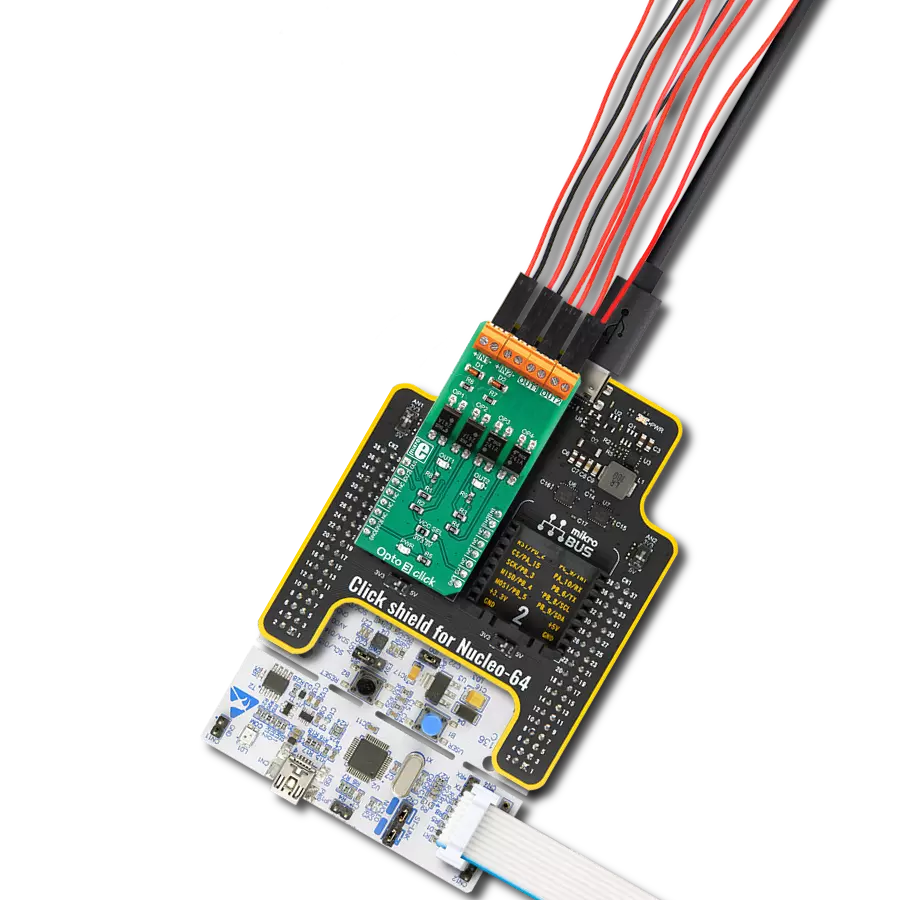
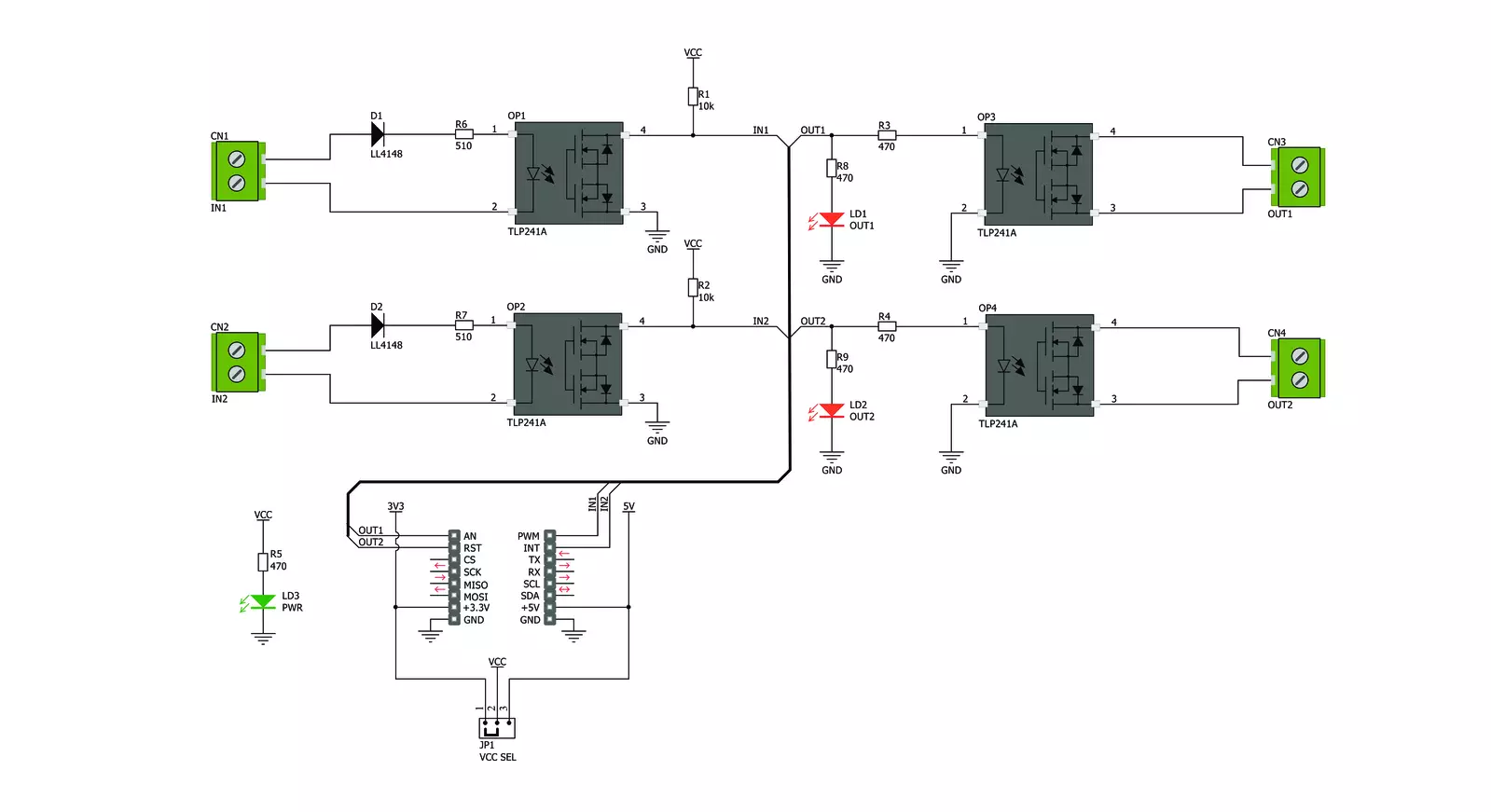
Opto 3 Click基于Toshiba Semiconductor的两对常开高质量固态继电器TLP241A。TLP241A是一种光隔离固态继电器(SSR),具有集成的IR LED和两个输出MOSFET。输出级与输入级没有任何电气接触,通过集成的IR LED产生的红外光激活。这实现了输入级和输出级之间的增强电隔离。输出级在关闭时可承受高达40V的电压。当激活时,由于集成的MOSFET的非常低的RDSON,它可以传导高达2A的电流。TLP241A能够有效替代传统使用的机械继电器,带来了全套继承的优点:由于没有运动部件,循环次数几乎无限制;输出触点上没有抖动效应;对机械冲击和环境影响有高抵抗力;激活所需的电流低;由于触点上不会积聚碳和锈蚀,电阻恒定;操作时不会产生火花或电弧;尺寸紧凑;隔离电压更高,等等。然而,与为低电流和电压设计的光耦合器(类似设备)不同,SSR并非设计用于作为信号线隔离器。SSR通常具有较慢的信号
传播时间。但它可以用于使用较低数据速率的各种通信协议,包括UART/RS232、1-Wire等。其中一对SSR由主控MCU驱动。这对SSR可以用于激活外部电路,充分利用TLP241A SSR的潜力。一个或两个SSR可以用作继电器,允许主控MCU控制较重的负载,如直流电机、一些在较高电位上操作的其他电路、LED灯带、LED阵列等。mikroBUS™引脚AN或RST上分别标记为OU1和OU2的高电平逻辑将激活集成的IR LED。它将打开SSR中的MOSFET,允许电流通过外部电路流动。两个红色LED,分别标记为OUT1和OUT 2,连接到每个MCU输出引脚。这些LED提供关于SSR状态的视觉反馈:如果亮起,则相应的SSR处于导通状态。SSR输出被路由到标记为OUT1和OUT2的两个螺钉端子,允许安全地连接外部电路。另一对SSR用于为外部信号提供光隔离,从而保护敏感的MCU引脚。在SSR未激活时,mikroBUS™的PWM和INT引脚分别标
记为IN1和IN2,由电阻拉至高电平逻辑。输入端的信号将激活相应的SSR,将IN1(IN2)引脚拉至低电平逻辑。由于电气隔离,输入端的信号可以与主控MCU处于不同的电位,防止两个GND之间的任何杂散电流流动。这也将保护主控MCU免受可能发生的静电放电(ESD)的影响。正确连接输入信号很重要。因此,两个输入端子明确标有+和-符号。串联的肖特基二极管为输入IR LED提供一些保护,但应注意不要超过TLP241A数据表中的规格。输入侧SSR上的上拉电阻连接到mikroBUS™的电源,在SSR未激活时提供高电平逻辑。在这种情况下,电源电压直接决定了施加到IN1和IN2引脚的电压水平。因此,Click板™上提供了一个标记为VCC SEL的SMD跳线,允许用户根据所使用的MCU及其能力在3.3V和5V之间选择逻辑电压水平。


功能概述
开发板
Clicker 2 for Kinetis 是一款紧凑型入门开发板,它将 Click 板™的灵活性带给您喜爱的微控制器,使其成为实现您想法的完美入门套件。它配备了一款板载 32 位 ARM Cortex-M4F 微控制器,NXP 半导体公司的 MK64FN1M0VDC12,两个 mikroBUS™ 插槽用于 Click 板™连接,一个 USB 连接器,LED 指示灯,按钮,一个 JTAG 程序员连接器以及两个 26 针头用于与外部电子设备的接口。其紧凑的设计和清晰、易识别的丝网标记让您能够迅速构建具有独特功能和特性
的小工具。Clicker 2 for Kinetis 开发套件的每个部分 都包含了使同一板块运行最高效的必要组件。除了可以选择 Clicker 2 for Kinetis 的编程方式,使用 USB HID mikroBootloader 或外部 mikroProg 连接器进行 Kinetis 编程外,Clicker 2 板还包括一个干净且调节过的开发套件电源供应模块。它提供了两种供电方式;通过 USB Micro-B 电缆,其中板载电压调节器为板上每个组件提供适当的电压水平,或使用锂聚合物 电池通过板载电池连接器供电。所有 mikroBUS™ 本
身支持的通信方法都在这块板上,包括已经建立良好的 mikroBUS™ 插槽、重置按钮和几个用户可配置的按钮及 LED 指示灯。Clicker 2 for Kinetis 是 Mikroe 生态系统的一个组成部分,允许您在几分钟内创建新的应用程序。它由 Mikroe 软件工具原生支持,得益于大量不同的 Click 板™(超过一千块板),其数量每天都在增长,它涵盖了原型制作的许多方面。

微控制器概述
MCU卡片 / MCU

建筑
ARM Cortex-M4
MCU 内存 (KB)
1024
硅供应商
NXP
引脚数
121
RAM (字节)
262144
使用的MCU引脚
mikroBUS™映射器
“仔细看看!”
Click board™ 原理图
一步一步来
项目组装

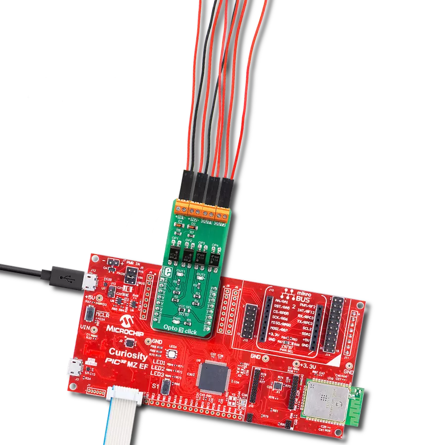
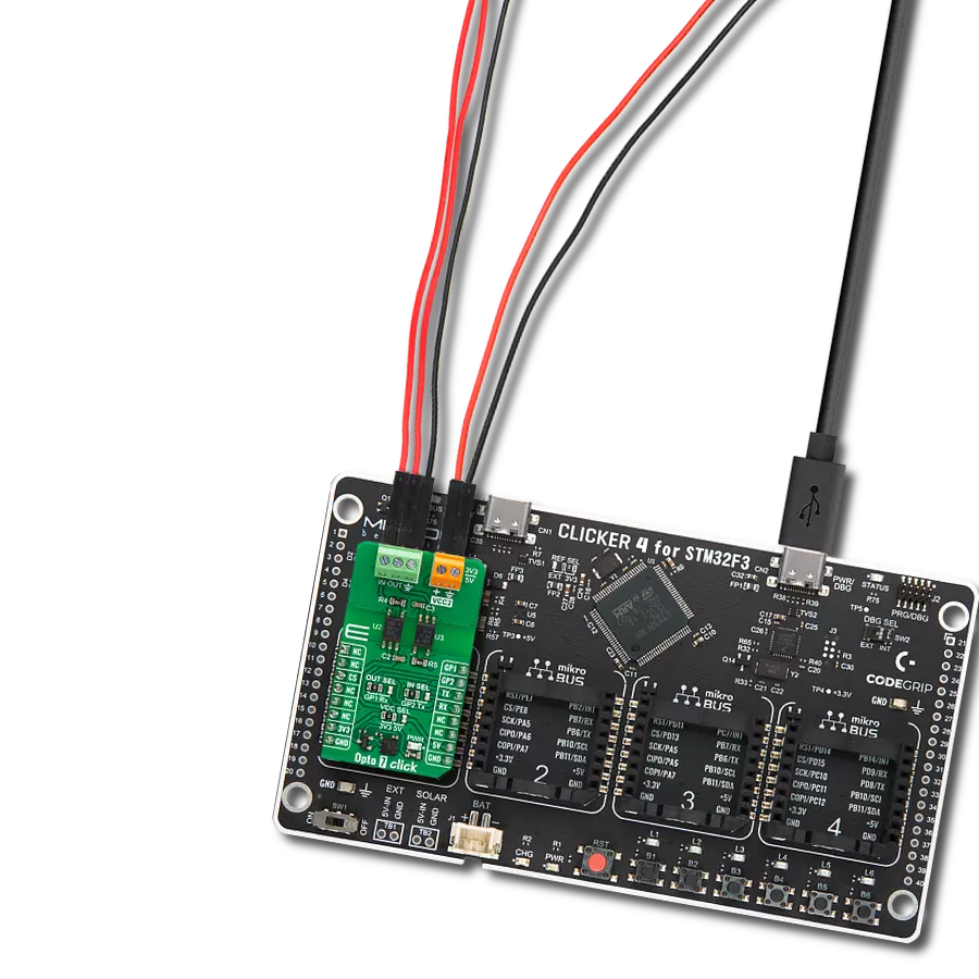
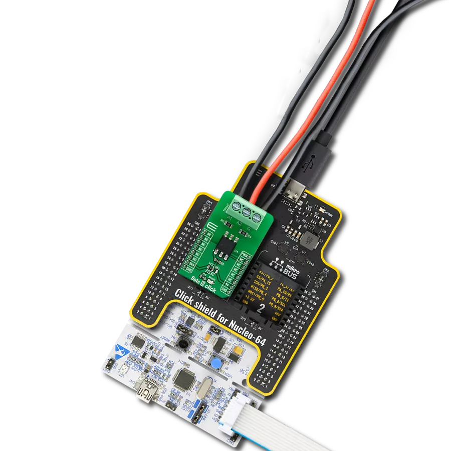
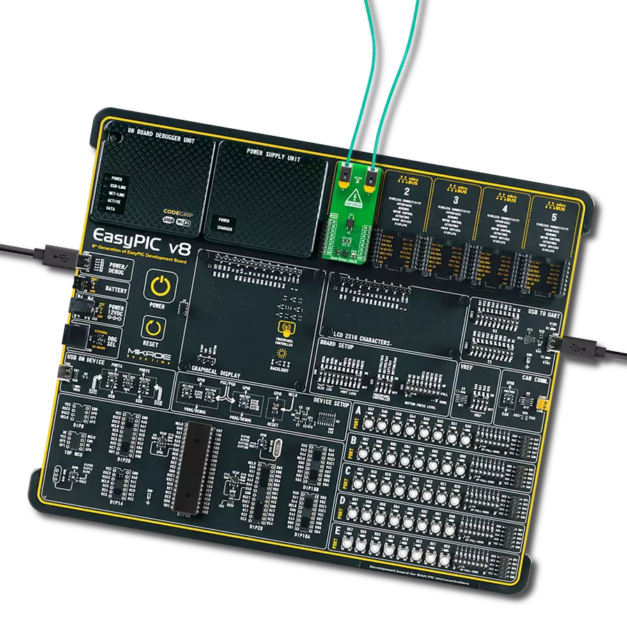
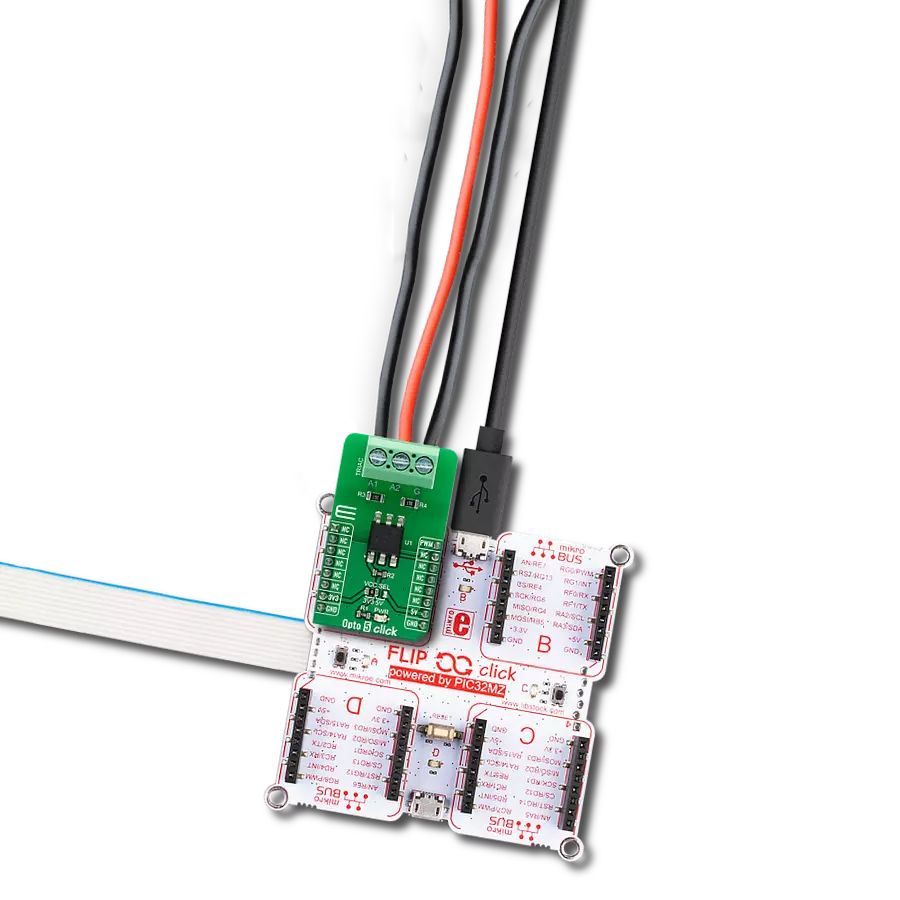
从选择您的开发板和Click板™开始。以Clicker 2 for Kinetis作为您的开发板开始。


软件支持
库描述
该库包含用于Opto 3 Click驱动程序的API。
关键功能:
opto3_get_in1- 获取输入1引脚状态的功能opto3_get_in2- 获取输入2引脚状态的功能opto3_set_out1- 设置输出1引脚状态的功能
开源
代码示例
完整的应用程序代码和一个现成的项目可以通过NECTO Studio包管理器直接安装到NECTO Studio。 应用程序代码也可以在MIKROE的GitHub账户中找到。
/*!
 * \file
 * \brief Opto 3 Click example
 *
 * # Description
 * Opto 3 Click to be used in applications that require reinforced galvanic
 * isolation for both their input and output stages.
 *
 * The demo application is composed of two sections :
 *
 * ## Application Init
 * Initializes GPIO interface.
 *
 * ## Application Task
 * Reads the input pins state and sets their respective output pins to the same logic state.
 * The output pins state will be displayed on the USB UART where you can track their changes.
 *
 * \author MikroE Team
 *
 */
// ------------------------------------------------------------------- INCLUDES

#include "board.h"
#include "log.h"
#include "opto3.h"

// ------------------------------------------------------------------ VARIABLES

static opto3_t opto3;
static log_t logger;

// ------------------------------------------------------ APPLICATION FUNCTIONS

void application_init ( void )
{
    log_cfg_t log_cfg;
    opto3_cfg_t cfg;

    /**
     * Logger initialization.
     * Default baud rate: 115200
     * Default log level: LOG_LEVEL_DEBUG
     * @note If USB_UART_RX and USB_UART_TX
     * are defined as HAL_PIN_NC, you will
     * need to define them manually for log to work.
     * See @b LOG_MAP_USB_UART macro definition for detailed explanation.
     */
    LOG_MAP_USB_UART( log_cfg );
    log_init( &logger, &log_cfg );
    log_info( &logger, " Application Init " );

    // Click initialization.
    opto3_cfg_setup( &cfg );
    OPTO3_MAP_MIKROBUS( cfg, MIKROBUS_1 );
    opto3_init( &opto3, &cfg );

    log_info( &logger, " Application Task " );
}

void application_task ( void )
{
    static uint8_t out1_state = 0;
    static uint8_t out2_state = 0;
    uint8_t in1_state = 0;
    uint8_t in2_state = 0;

    in1_state = opto3_get_in1( &opto3 );
    in2_state = opto3_get_in2( &opto3 );

    if ( in1_state != out1_state )
    {
        out1_state = in1_state;
        opto3_set_out1( &opto3, out1_state );
        log_printf( &logger, " OUT1 state: %u\r\n", ( uint16_t ) out1_state );
    }

    if ( in2_state != out2_state )
    {
        out2_state = in2_state;
        opto3_set_out2( &opto3, out2_state );
        log_printf( &logger, " OUT2 state: %u\r\n", ( uint16_t ) out2_state );
    }
}

int main ( void )
{
    /* Do not remove this line or clock might not be set correctly. */
    #ifdef PREINIT_SUPPORTED
    preinit();
    #endif

    application_init( );

    for ( ; ; )
    {
        application_task( );
    }

    return 0;
}


// ------------------------------------------------------------------------ END