使用LED1202和PIC32MZ2048EFM100提升您的照明体验
更亮的光芒,更长的寿命!
已发布 6月 27, 2024
点击板
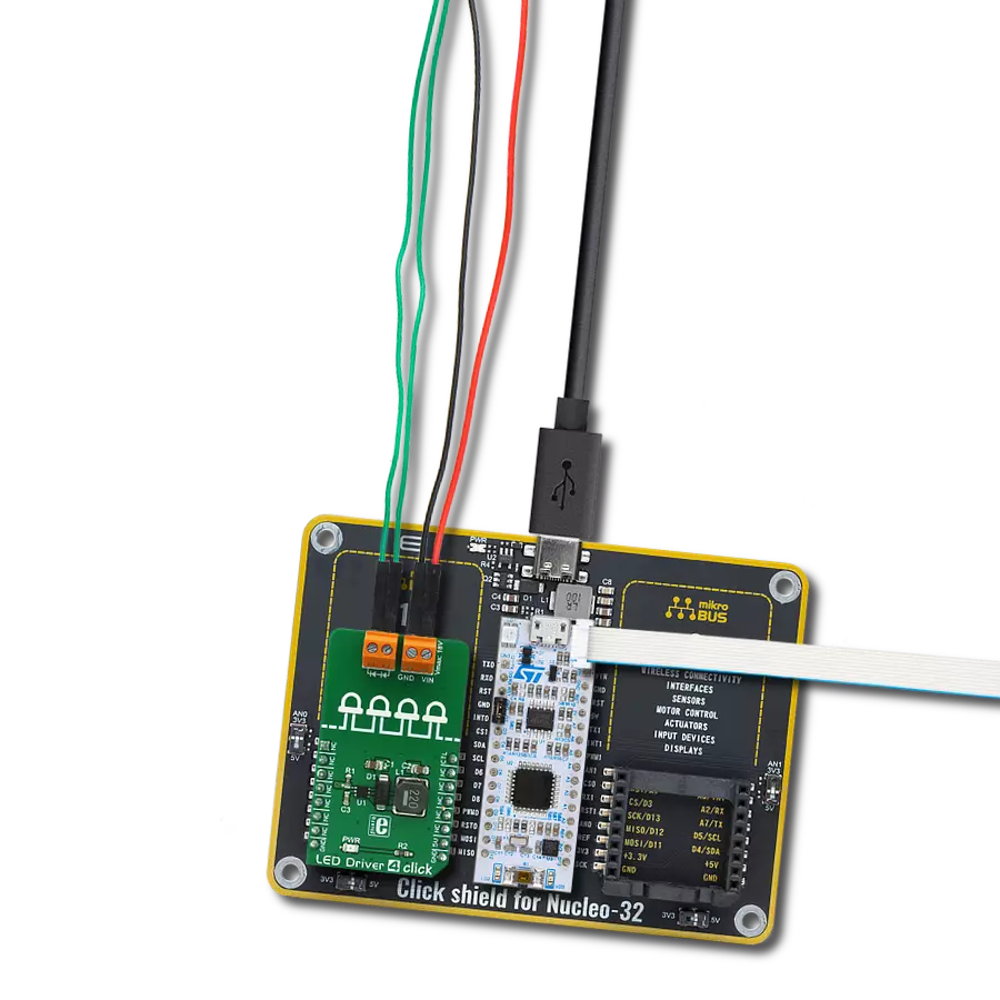
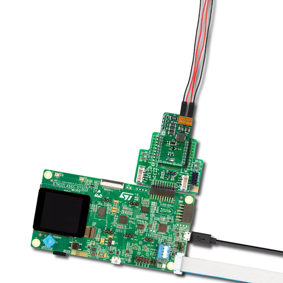
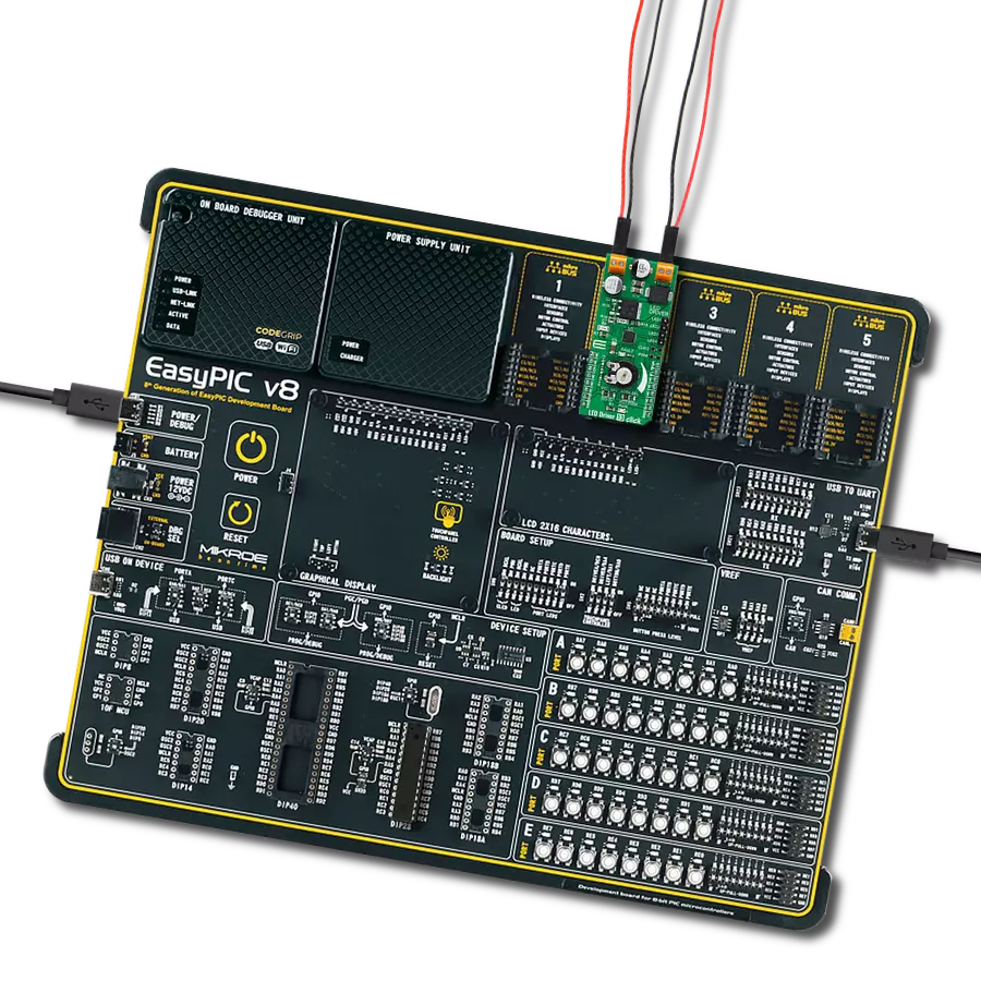
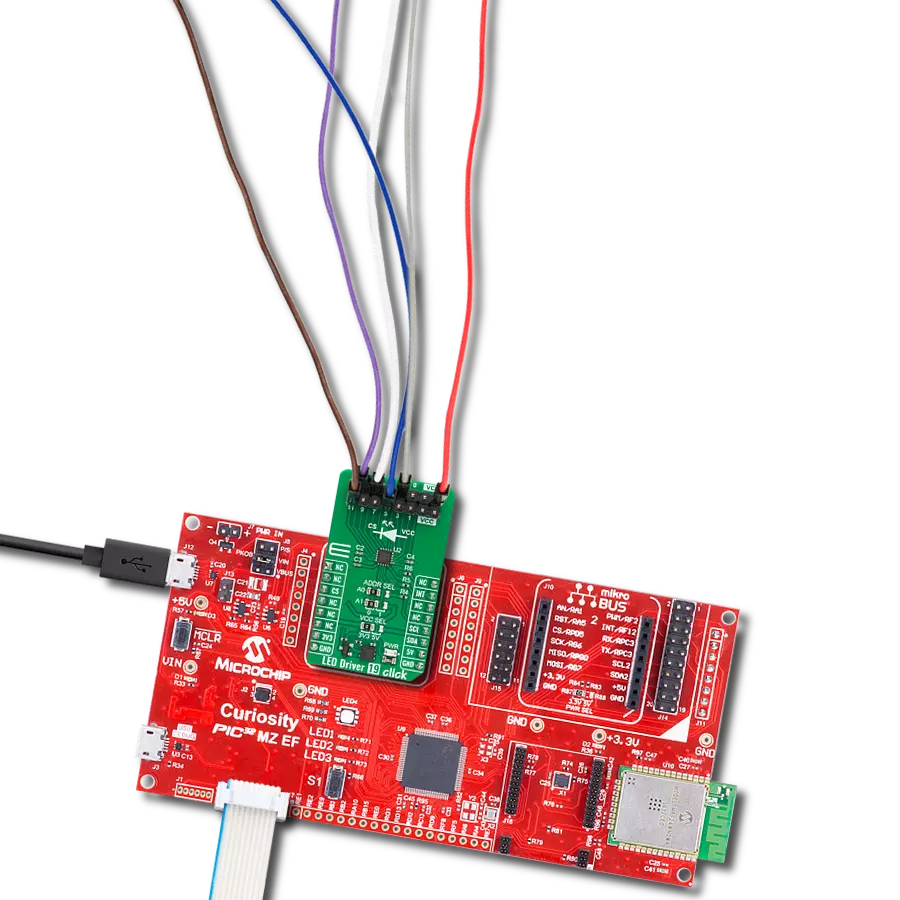
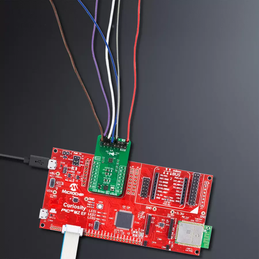
LED Driver 19 Click
开发板
Curiosity PIC32 MZ EF
编译器
NECTO Studio
微控制器单元
PIC32MZ2048EFM100
通过使用我们可靠的LED驱动解决方案升级您的照明体验,该解决方案经过精心设计,旨在提升亮度、延长寿命和实现最佳效率,因为您的灯光值得多年来保持最明亮的状态。
A
A
硬件概览
它是如何工作的?
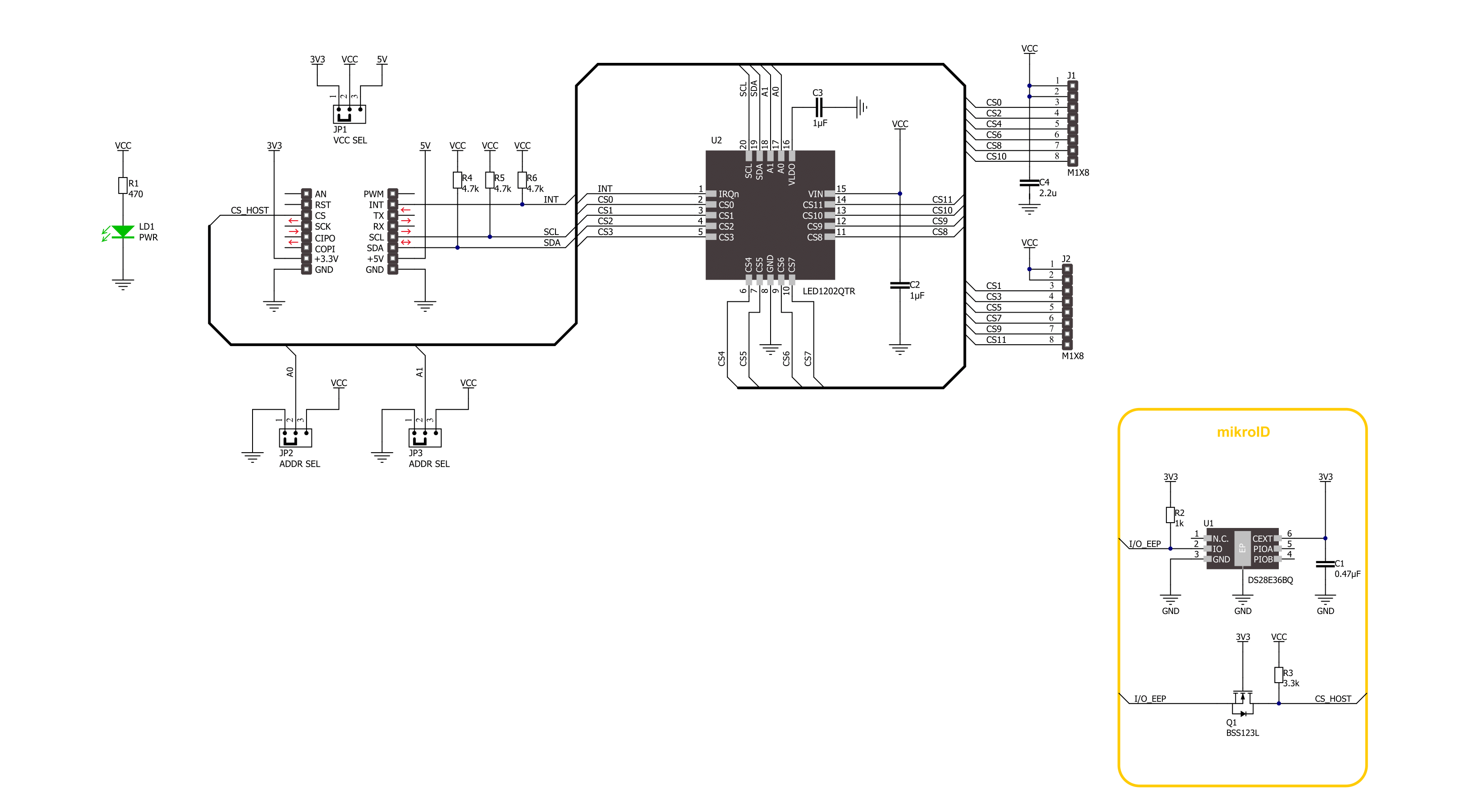
LED Driver 19 Click基于STMicroelectronics的LED1202,这是一款12通道低静态电流LED驱动器。其内部非易失性存储器可以存储多达8种不同的模式,每种模式具有特定的输出配置,从而无需MCU干预即可实现自动排序。每个通道具有220Hz的输出PWM调光频率和12位分辨率。模拟调光范围从1mA到20mA,每个通道有256个步骤,且通用所
有模式。此外,通过使用PWM或模拟模式中的一种,可以结合使用两者以实现对LED亮度的全面控制。该LED驱动器还具有内置的开路LED检测和热关断功能,在过温条件下关闭所有输出驱动器。LED Driver 19 Click使用标准I2C 2线接口与主机MCU通信。I2C地址可以通过两个ADDR SEL跳线选择,默认情况下均为0。如果发生故障或条件(如开路
LED、过温、模式结束和帧开始),LED1202驱动器可以在INT引脚上产生中断。INT引脚以低电平通知系统这些状态。该Click板可以在3.3V或5V逻辑电压水平下操作,通过VCC SEL跳线选择。这种方式,3.3V和5V的MCU都可以正确使用通信线路。此外,该Click板配备了包含易于使用的函数和示例代码的库,可以用于进一步开发。

功能概述
开发板
Curiosity PIC32 MZ EF 开发板是一个完全集成的 32 位开发平台,特点是高性能的 PIC32MZ EF 系列(PIC32MZ2048EFM),该系列具有 2MB Flash、512KB RAM、集成的浮点单元(FPU)、加密加速器和出色的连接选项。它包括一个集成的程序员和调试器,无需额外硬件。用户可以通过 MIKROE
mikroBUS™ Click™ 适配器板扩展功能,通过 Microchip PHY 女儿板添加以太网连接功能,使用 Microchip 扩展板添加 WiFi 连接能力,并通过 Microchip 音频女儿板添加音频输入和输出功能。这些板完全集成到 PIC32 强大的软件框架 MPLAB Harmony 中,该框架提供了一个灵活且模块化的接口
来应用开发、一套丰富的互操作软件堆栈(TCP-IP、USB)和易于使用的功能。Curiosity PIC32 MZ EF 开发板提供了扩展能力,使其成为连接性、物联网和通用应用中快速原型设计的绝佳选择。

微控制器概述
MCU卡片 / MCU

建筑
PIC32
MCU 内存 (KB)
2048
硅供应商
Microchip
引脚数
100
RAM (字节)
524288
使用的MCU引脚
mikroBUS™映射器
“仔细看看!”
Click board™ 原理图
一步一步来
项目组装

从选择您的开发板和Click板™开始。以Curiosity PIC32 MZ EF作为您的开发板开始。


软件支持
库描述
该库包含 LED Driver 19 Click 驱动程序的 API。
关键功能:
leddriver19_sw_reset- LED Driver 19软件重置功能。leddriver19_enable_channels- LED Driver 19启用通道功能。leddriver19_set_pattern_pwm- LED Driver 19设置模式PWM值功能。
开源
代码示例
完整的应用程序代码和一个现成的项目可以通过NECTO Studio包管理器直接安装到NECTO Studio。 应用程序代码也可以在MIKROE的GitHub账户中找到。
/*!
 * @file main.c
 * @brief LED Driver 19 Click example
 *
 * # Description
 * This library contains API for LED Driver 19 Click driver.
 * The library initializes and defines the I2C bus drivers to
 * write the default configuration for a PWM output value
 * of the out pins.
 *
 * The demo application is composed of two sections :
 *
 * ## Application Init
 * Initializes the driver and performs default configuration, sets the device
 * in output enabled mode and checks communication by reading device ID.
 *
 * ## Application Task
 * This example demonstrates the use of the LED Driver 19 Click board by
 * changing PWM values of all channels from maximum to minimum turning
 * LEDs on and off in the process.
 *
 * @author Stefan Ilic
 *
 */

#include "board.h"
#include "log.h"
#include "leddriver19.h"

static leddriver19_t leddriver19;
static log_t logger;

void application_init ( void )
{
    log_cfg_t log_cfg;  /**< Logger config object. */
    leddriver19_cfg_t leddriver19_cfg;  /**< Click config object. */

    /**
     * Logger initialization.
     * Default baud rate: 115200
     * Default log level: LOG_LEVEL_DEBUG
     * @note If USB_UART_RX and USB_UART_TX
     * are defined as HAL_PIN_NC, you will
     * need to define them manually for log to work.
     * See @b LOG_MAP_USB_UART macro definition for detailed explanation.
     */
    LOG_MAP_USB_UART( log_cfg );
    log_init( &logger, &log_cfg );
    log_info( &logger, " Application Init " );

    // Click initialization.
    leddriver19_cfg_setup( &leddriver19_cfg );
    LEDDRIVER19_MAP_MIKROBUS( leddriver19_cfg, MIKROBUS_1 );
    if ( I2C_MASTER_ERROR == leddriver19_init( &leddriver19, &leddriver19_cfg ) )
    {
        log_error( &logger, " Communication init." );
        for ( ; ; );
    }

    uint8_t device_id;

    leddriver19_read_reg( &leddriver19, LEDDRIVER19_REG_DEVICE_ID, &device_id );
    if ( LEDDRIVER19_DEVICE_ID != device_id )
    {
        log_error( &logger, " Communication error." );
        for ( ; ; );
    }

    if ( LEDDRIVER19_ERROR == leddriver19_default_cfg ( &leddriver19 ) )
    {
        log_error( &logger, " Default configuration." );
        for ( ; ; );
    }

    log_info( &logger, " Application Task " );
}

void application_task ( void )
{
    for ( uint8_t n_cnt = LEDDRIVER19_CH_SEL_0; n_cnt <= LEDDRIVER19_CH_SEL_11; n_cnt++ )
    {
        leddriver19_set_pattern_pwm( &leddriver19, LEDDRIVER19_PATSEL_0, n_cnt, 100  );
        Delay_ms ( 100 );
    }
    Delay_ms ( 1000 );

    for ( uint8_t n_cnt = LEDDRIVER19_CH_SEL_0; n_cnt <= LEDDRIVER19_CH_SEL_11; n_cnt++ )
    {
        leddriver19_set_pattern_pwm( &leddriver19, LEDDRIVER19_PATSEL_0, n_cnt, 0  );
        Delay_ms ( 100 );
    }
    Delay_ms ( 1000 );
}

int main ( void )
{
    /* Do not remove this line or clock might not be set correctly. */
    #ifdef PREINIT_SUPPORTED
    preinit();
    #endif

    application_init( );

    for ( ; ; )
    {
        application_task( );
    }

    return 0;
}

// ------------------------------------------------------------------------ END