使用PD-V11和PIC32MZ2048EFM100创建响应迅速、节能的系统,以适应用户的存在和需求
从科幻到现实

已发布 6月 25, 2024
点击板
Microwave Click
开发板
Curiosity PIC32 MZ EF
编译器
NECTO Studio
微控制器单元
PIC32MZ2048EFM100
这种利用多普勒效应和微波的解决方案能够精确检测和追踪运动,为广泛的应用领域打开了大门。
A
A
硬件概览
它是如何工作的?
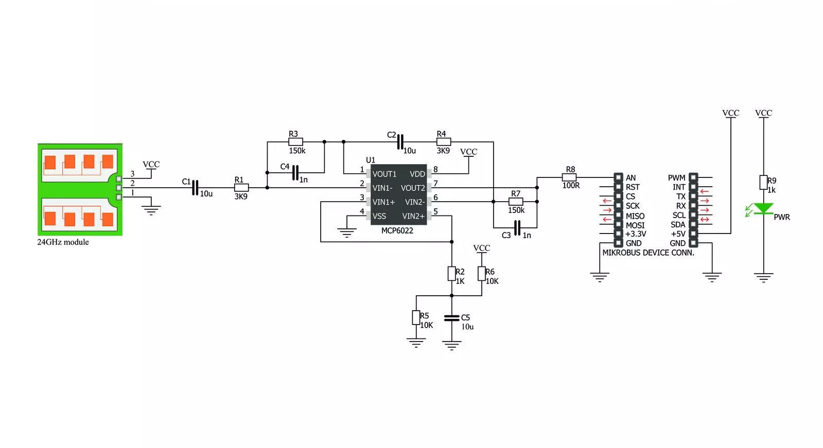
Microwave Click 基于 Pdlux 的 PD-V11,一个 24GHz 微波运动传感器。Microwave Click 的典型用途是在各种应用和设备中作为接近或运动探测器。Microwave Click 通过使用多普勒效应来探测运动或接近。机载微波运动传感器发射波,并在这些波击中物体后接收它们,其频率发生变化。Microwave Click 不需要光学可见性即可工作,其波可以穿透许多种类的屏障和障碍。Microwave Click 利用多普勒效应检测物体的运动。当 PD-V11 微波传感器开启时,它
开始发射固定频率的无线电波。当波撞击一个移动物体时,它们会反射回 PD-V11 微波运动传感器,其频率根据物体移动的速度和方向发生变化。多普勒效应——波的频率变化,当观察者和物体相互接近或远离时发生变化。一个典型的多普勒效应例子是,当一个带有警报的车辆经过时,你会听到警报的音调降低。PD-V11 微波运动传感器具有低功耗、低噪声和低无线电功率输出。请查阅数据表以了解更多信息。PD-V11 微波运动传感器接收反射波并将其
转换为电压信号。这个信号的大小为几百微伏,因此它被发送到 MCP6022,MCP6022 放大信号,以便通过 mikroBUS™ 的模拟引脚读取。该信号被放大至 3.3V。放大后,该信号被路由到 mikroBUS™ 线上的模拟引脚(OUT)。通过测量该信号的幅度可以确定物体的接近程度,通过确定其频率可以判断速度/方向。


功能概述
开发板
Curiosity PIC32 MZ EF 开发板是一个完全集成的 32 位开发平台,特点是高性能的 PIC32MZ EF 系列(PIC32MZ2048EFM),该系列具有 2MB Flash、512KB RAM、集成的浮点单元(FPU)、加密加速器和出色的连接选项。它包括一个集成的程序员和调试器,无需额外硬件。用户可以通过 MIKROE
mikroBUS™ Click™ 适配器板扩展功能,通过 Microchip PHY 女儿板添加以太网连接功能,使用 Microchip 扩展板添加 WiFi 连接能力,并通过 Microchip 音频女儿板添加音频输入和输出功能。这些板完全集成到 PIC32 强大的软件框架 MPLAB Harmony 中,该框架提供了一个灵活且模块化的接口
来应用开发、一套丰富的互操作软件堆栈(TCP-IP、USB)和易于使用的功能。Curiosity PIC32 MZ EF 开发板提供了扩展能力,使其成为连接性、物联网和通用应用中快速原型设计的绝佳选择。

微控制器概述
MCU卡片 / MCU

建筑
PIC32
MCU 内存 (KB)
2048
硅供应商
Microchip
引脚数
100
RAM (字节)
524288
使用的MCU引脚
mikroBUS™映射器
“仔细看看!”
Click board™ 原理图
一步一步来
项目组装

从选择您的开发板和Click板™开始。以Curiosity PIC32 MZ EF作为您的开发板开始。


实时跟踪您的结果
应用程序输出
1. 应用程序输出 - 在调试模式下,“应用程序输出”窗口支持实时数据监控,直接提供执行结果的可视化。请按照提供的教程正确配置环境,以确保数据正确显示。

2. UART 终端 - 使用UART Terminal通过USB to UART converter监视数据传输,实现Click board™与开发系统之间的直接通信。请根据项目需求配置波特率和其他串行设置,以确保正常运行。有关分步设置说明,请参考提供的教程。

3. Plot 输出 - Plot功能提供了一种强大的方式来可视化实时传感器数据,使趋势分析、调试和多个数据点的对比变得更加直观。要正确设置,请按照提供的教程,其中包含使用Plot功能显示Click board™读数的分步示例。在代码中使用Plot功能时,请使用以下函数:plot(insert_graph_name, variable_name);。这是一个通用格式,用户需要将“insert_graph_name”替换为实际图表名称,并将“variable_name”替换为要显示的参数。

软件支持
库描述
这个库包含了 Microwave Click 驱动程序的 API。
关键函数:
microwave_generic_read- 通用 ADC 读取函数
开源
代码示例
完整的应用程序代码和一个现成的项目可以通过NECTO Studio包管理器直接安装到NECTO Studio。 应用程序代码也可以在MIKROE的GitHub账户中找到。
/*!
* \file main.c
* \brief Microwave Click example
*
* # Description
* This is an example which demonstrates the use of Microwave Click board.
* Microwave click reads ADC results, takes exact amount of samples,
* calculation of difference between taken samples and reference ADC value, and
* reports movement if difference is greater/lower than selected threshold value.
*
* The demo application is composed of two sections :
*
* ## Application Init
* Initializes the ADC and uart console where the results will be displayed.
* Also calculates the reference ADC value for Microwave Click board.
*
* ## Application Task
* Reads the AD converted results and compares this results with the previously
* calculated reference value, taking into account the choosen threshold value
* which controls the sensor sensitivity. All data is being displayed on the
* USB UART where you can track their changes.
*
*
* \author Nemanja Medakovic
*
*/
// ------------------------------------------------------------------- INCLUDES
#include "board.h"
#include "log.h"
#include "microwave.h"
// ------------------------------------------------------------------ VARIABLES
static microwave_t microwave;
static log_t logger;
static uint16_t reference;
static uint32_t sum;
static uint16_t old_detector = 0;
// ------------------------------------------------------ APPLICATION FUNCTIONS
void application_init( void )
{
microwave_cfg_t cfg;
log_cfg_t log_cfg;
/**
* Logger initialization.
* Default baud rate: 115200
* Default log level: LOG_LEVEL_DEBUG
* @note If USB_UART_RX and USB_UART_TX
* are defined as HAL_PIN_NC, you will
* need to define them manually for log to work.
* See @b LOG_MAP_USB_UART macro definition for detailed explanation.
*/
LOG_MAP_USB_UART( log_cfg );
log_init( &logger, &log_cfg );
log_info( &logger, "---- Application Init ----" );
// Click initialization.
microwave_cfg_setup( &cfg );
MICROWAVE_MAP_MIKROBUS( cfg, MIKROBUS_1 );
microwave_init( µwave, &cfg );
Delay_ms( 100 );
log_printf( &logger, " Calibrating the sensor...\r\n" );
log_printf( &logger, " There must be no movement near the sensor!\r\n" );
log_printf( &logger, "*********************************************\r\n" );
Delay_ms( 3000 );
sum = 0;
for ( uint8_t cnt = 0; cnt < MICROWAVE_SAMPLES_COUNT_100; cnt++ )
{
sum += microwave_generic_read( µwave );
}
reference = sum / MICROWAVE_SAMPLES_COUNT_100;
log_printf( &logger, " The sensor has been calibrated!\r\n" );
log_printf( &logger, "** Reference value: %d\r\n", reference );
log_printf( &logger, "*********************************************\r\n" );
Delay_ms( 1000 );
}
void application_task( void )
{
microwave_data_t adc_sample;
uint16_t detector;
uint8_t sampler;
uint8_t cnt = 0;
sum = 0;
for ( sampler = 0; sampler < MICROWAVE_SAMPLES_COUNT_100; sampler++ )
{
adc_sample = microwave_generic_read( µwave );
sum += adc_sample;
cnt++;
}
if ( cnt )
{
detector = sum / cnt;
if ( ( ( detector + MICROWAVE_THRESHOLD_10 ) < reference ||
( detector - MICROWAVE_THRESHOLD_10 ) > reference ) &&
old_detector != detector )
{
log_printf( &logger, "** MOVE DETECTED!\r\n" );
log_printf( &logger, "** Detector value : %d\r\n", detector );
log_printf( &logger, "**************************\r\n" );
old_detector = detector;
Delay_ms( 100 );
}
}
}
void main( void )
{
application_init( );
for ( ; ; )
{
application_task( );
}
}
// ------------------------------------------------------------------------ END


