使用SDS001和PIC32MZ2048EFM100在不同阶段捕获和响应用户输入
双信号,双控制:微动开关创新

已发布 6月 25, 2024
点击板
Tamper Click
开发板
Curiosity PIC32 MZ EF
编译器
NECTO Studio
微控制器单元
PIC32MZ2048EFM100
了解这款多功能微动开关如何为您的项目释放新的潜力,使您能够设计响应按下和释放动作的解决方案。
A
A
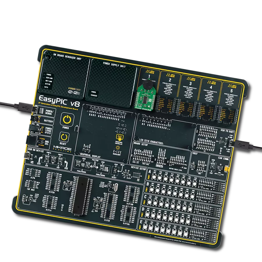
硬件概览
它是如何工作的?
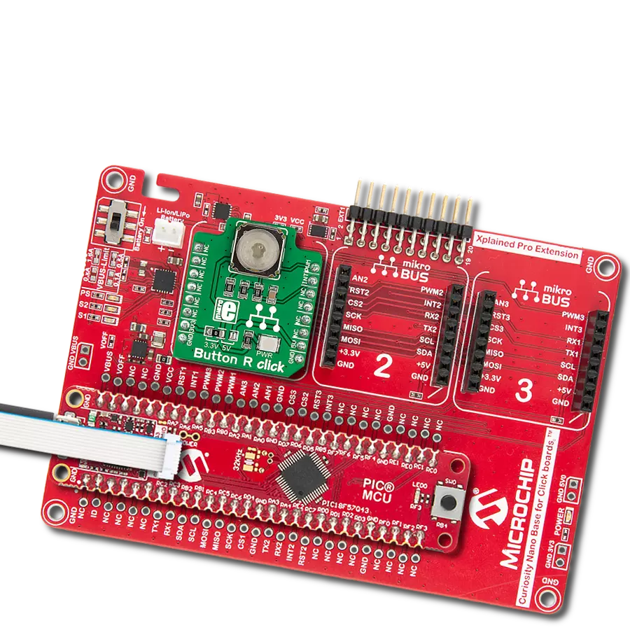
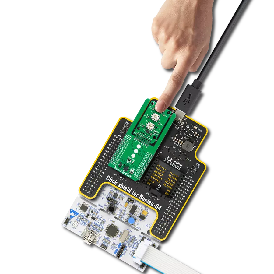
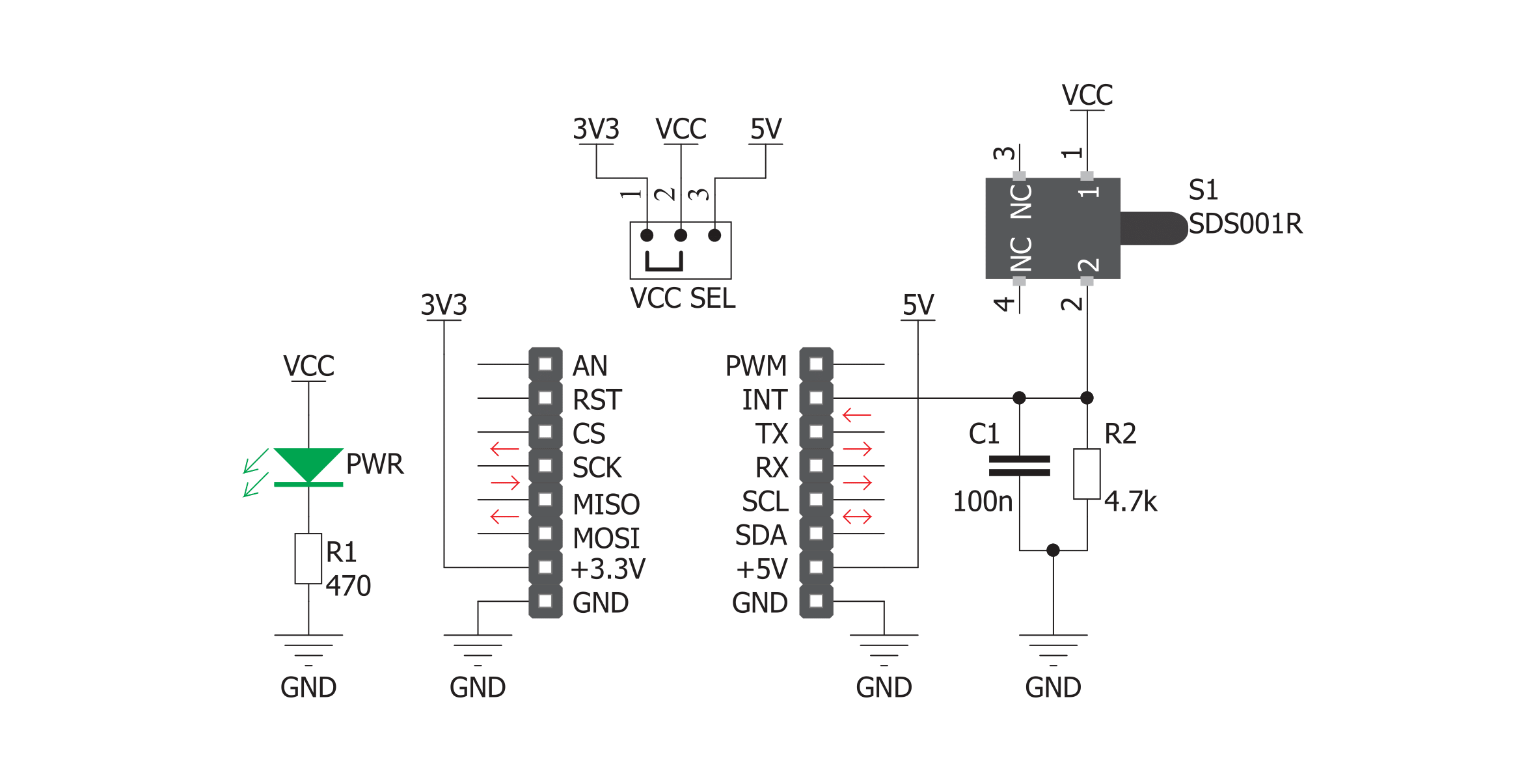
Tamper Click基于C&K的SDS001,这是一款低轮廓侧向触发检测开关。开关本身作为一个按键,具有2个NO(常开)接点,当施加力量到开关的小柱状按钮时,这些接点会短路。这种类型的开关通常安装在PCB的边缘,以便可以轻松地通过施加压力到开关的元件来触发开关。施加的压力闭合电路,将连接到开关第一个引脚的VCC与mikroBUS™上的INT引脚相
连。然后,微控制器能够检测到INT引脚上的高逻辑电平,然后可以执行所需的任务。施加的RC滤波器既用作去抖动电路,又用作开关端子的下拉,以防止浮动状态。所使用的开关本身旨在与数字信号电平一起工作,因此其电气特性专门针对此目的进行了调整:100mΩ的低接触电阻,12V下100mA的相对低接触额定值以及5万次切换周期之前的故障。这些特性使
其特别适用于数字信号应用。该Click板™可以通过VCC SEL跳线选择3.3V或5V逻辑电压级别。这样,既支持3.3V又支持5V的MCU可以正确使用通信线。此外,该Click板™配备有一个包含易于使用的函数和示例代码的库,可作为进一步开发的参考。


功能概述
开发板
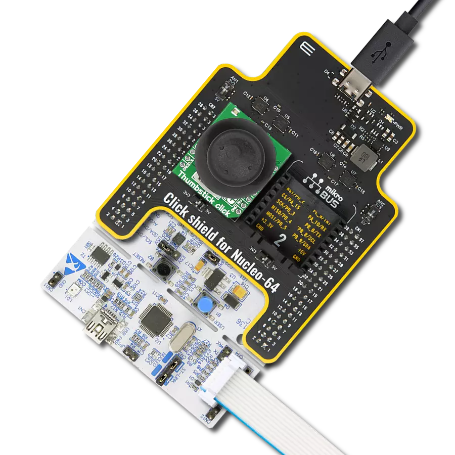
Curiosity PIC32 MZ EF 开发板是一个完全集成的 32 位开发平台,特点是高性能的 PIC32MZ EF 系列(PIC32MZ2048EFM),该系列具有 2MB Flash、512KB RAM、集成的浮点单元(FPU)、加密加速器和出色的连接选项。它包括一个集成的程序员和调试器,无需额外硬件。用户可以通过 MIKROE
mikroBUS™ Click™ 适配器板扩展功能,通过 Microchip PHY 女儿板添加以太网连接功能,使用 Microchip 扩展板添加 WiFi 连接能力,并通过 Microchip 音频女儿板添加音频输入和输出功能。这些板完全集成到 PIC32 强大的软件框架 MPLAB Harmony 中,该框架提供了一个灵活且模块化的接口
来应用开发、一套丰富的互操作软件堆栈(TCP-IP、USB)和易于使用的功能。Curiosity PIC32 MZ EF 开发板提供了扩展能力,使其成为连接性、物联网和通用应用中快速原型设计的绝佳选择。

微控制器概述
MCU卡片 / MCU

建筑
PIC32
MCU 内存 (KB)
2048
硅供应商
Microchip
引脚数
100
RAM (字节)
524288
使用的MCU引脚
mikroBUS™映射器
“仔细看看!”
Click board™ 原理图
一步一步来
项目组装

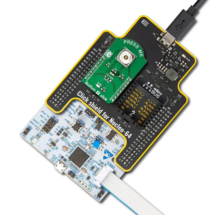
从选择您的开发板和Click板™开始。以Curiosity PIC32 MZ EF作为您的开发板开始。


软件支持
库描述
这个库包含了Tamper Click驱动程序的API。
关键函数:
tamper_state- 函数显示开关的状态
开源
代码示例
完整的应用程序代码和一个现成的项目可以通过NECTO Studio包管理器直接安装到NECTO Studio。 应用程序代码也可以在MIKROE的GitHub账户中找到。
/*!
 * \file
 * \brief Tamper Click example
 *
 * # Description
 * Tamper Click is equipped with side-actuated detect switch. The switch itself acts as
 * a push button and has 2 Normally Open terminals, which get shorted when the force is applied.
 * The applied pressure closes the circuit, connecting the VCC routed to the first pin
 * of the switch with the INT pin on the mikroBUS. The microcontroller is then able to detect
 * a high logical level on the INT pin and the desired task can then be executed.
 *
 * The demo application is composed of two sections :
 *
 * ## Application Init
 * Initialization driver enables GPIO and also starts write log.
 *
 * ## Application Task
 * This is an example which demonstrates the use of Tamper Click board.
 * It detects whether the state of switch on Tamper Click is changes to open or to closed.
 * Results are being sent to the Usart Terminal where you can keep track of their changes.
 *
 *
 * \author MikroE Team
 *
 */
// ------------------------------------------------------------------- INCLUDES

#include "board.h"
#include "log.h"
#include "tamper.h"

// ------------------------------------------------------------------ VARIABLES

static tamper_t tamper;
static log_t logger;

static uint8_t switch_state = 0;
static uint8_t switch_state_old = 1;

// ------------------------------------------------------ APPLICATION FUNCTIONS

void application_init ( void )
{
    log_cfg_t log_cfg;
    tamper_cfg_t cfg;

    /**
     * Logger initialization.
     * Default baud rate: 115200
     * Default log level: LOG_LEVEL_DEBUG
     * @note If USB_UART_RX and USB_UART_TX
     * are defined as HAL_PIN_NC, you will
     * need to define them manually for log to work.
     * See @b LOG_MAP_USB_UART macro definition for detailed explanation.
     */
    LOG_MAP_USB_UART( log_cfg );
    log_init( &logger, &log_cfg );
    log_info(&logger, "---- Application Init ----");

    //  Click initialization.

    tamper_cfg_setup( &cfg );
    TAMPER_MAP_MIKROBUS( cfg, MIKROBUS_1 );
    tamper_init( &tamper, &cfg );
}

void application_task ( void )
{
    switch_state = tamper_state( &tamper );

    if ( switch_state == 1 && switch_state_old == 0 )
    {
        log_printf( &logger, "      Closed     \r\n" );
        log_printf( &logger, "- - - - - - - - -\r\n" );
        switch_state_old = 1;
    }

    if ( switch_state == 0 && switch_state_old == 1 )
    {
        log_printf( &logger, "       Open      \r\n" );
        log_printf( &logger, "- - - - - - - - -\r\n" );
        switch_state_old = 0;
    }
}

int main ( void )
{
    /* Do not remove this line or clock might not be set correctly. */
    #ifdef PREINIT_SUPPORTED
    preinit();
    #endif

    application_init( );

    for ( ; ; )
    {
        application_task( );
    }

    return 0;
}


// ------------------------------------------------------------------------ END
额外支持
资源
类别:按钮/开关