使用MIC7401和PIC18F57Q43体验无缝升降压电源控制
掌握电压调节的艺术

已发布 6月 24, 2024
点击板
Buck & Boost Click
开发板
Curiosity Nano with PIC18F57Q43
编译器
NECTO Studio
微控制器单元
PIC18F57Q43
实现卓越的负载调节,确保在不同负载条件下输出电压稳定,适用于精密驱动应用。
A
A
硬件概览
它是如何工作的?
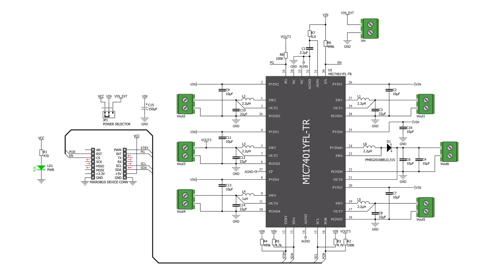
Buck & Boost Click 基于 Microchip 的 MIC7401,这是一款强大的高度集成可配置电源管理集成电路 (PMIC),具有降压和升压调节器、高速 I2C 接口、内部 EEPROM 存储器和微功耗关断功能。该 Click 板™ 具有五个 3A 同步降压调节器,采用高速自适应导通时间控制,以及一个升压调节器,提供高达 200mA 输出电流的闪存编程电源。升压调节器具有输出断开开关,如果检测到对地短路故障,该开关将打开。MIC7401 提供两种不同的工作模式,待机模式和正常模式,旨在提供适用于便携手持设备和信息娱乐应用的节能解决方案。在正常模式下,可编程的开关转换器可以配置
支持多种启动排序、时间、软启动斜坡、输出电压水平、电流限制水平和每个通道的输出放电。在待机模式下,可以通过关闭输出或将输出电压更改为较低水平来将此 PMIC 配置为低功耗状态。通过 I2C 通信或 mikroBUS™ 插座的 STB 引脚,可以实现独立退出待机模式。Buck & Boost Click 使用标准 I2C 双线接口与 MCU 通信,标准模式下频率最高为 100kHz,快速模式下最高为 400kHz,高速模式下最高为 3.4MHz。该 Click 板™ 还包含路由到 mikroBUS™ 插座上的 CS、AN、PWM 和 INT 引脚的附加功能。标记为 EN 的 CS 引脚表示一个使能引脚,可关闭设备以实现额外的节
能。标记为 STB 的 PWM 引脚表示待机复位功能,通过降低电源电压或关闭电源来减少总功耗。除了这些功能外,该 Click 板™ 具有电源开启复位,在 POR 延迟时间过去后变高,以及当所有调节器的电源良好标志都变高时被拉高的全局电源良好输出。该 Click 板™ 设计为可在 mikroBUS™ 提供的 5V 逻辑电压水平下运行,或从外部输入端子选择 2.4V 至 5.5V 范围内的电压,通过 VIN SEL 跳线选择。通过使用 mikroBUS™ 插座的逻辑电压水平或外部电压电源,使 3.3V 和 5V 兼容的 MCU 都能正确使用 I2C 通信线路。

功能概述
开发板
PIC18F57Q43 Curiosity Nano 评估套件是一款尖端的硬件平台,旨在评估 PIC18-Q43 系列内的微控制器。其设计的核心是包含了功能强大的 PIC18F57Q43 微控制器(MCU),提供先进的功能和稳健的性能。这个评估套件的关键特点包括一个黄 色用户 LED 和一个响应灵敏的机械用户开关,提供无
缝的交互和测试。为一个 32.768kHz 水晶振荡器足迹提供支持,确保精准的定时能力。套件内置的调试器拥有一个绿色电源和状态 LED,使编程和调试变得直观高效。此外,增强其实用性的还有虚拟串行端口 (CDC)和一个调试 GPIO 通道(DGI GPIO),提供广泛的连接选项。该套件通过 USB 供电,拥有由
MIC5353 LDO 调节器提供支持的可调目标电压功能,确保在 1.8V 至 5.1V 的输出电压范围内稳定运行,最大输出电流为 500mA,受环境温度和电压限制。

微控制器概述
MCU卡片 / MCU

建筑
PIC
MCU 内存 (KB)
128
硅供应商
Microchip
引脚数
48
RAM (字节)
8196
你完善了我!
配件
Curiosity Nano Base for Click boards 是一款多功能硬件扩展平台,专为简化 Curiosity Nano 套件与扩展板之间的集成而设计,特别针对符合 mikroBUS™ 标准的 Click 板和 Xplained Pro 扩展板。这款创新的基板(屏蔽板)提供了无缝的连接和扩展可能性,简化了实验和开发过程。主要特点包括从 Curiosity Nano 套件提供 USB 电源兼容性,以及为增强灵活性而提供的另一种外部电源输入选项。板载锂离子/锂聚合物充电器和管理电路确保电池供电应用的平稳运行,简化了使用和管理。此外,基板内置了一个固定的 3.3V 电源供应单元,专用于目标和 mikroBUS™ 电源轨,以及一个固定的 5.0V 升压转换器,专供 mikroBUS™ 插座的 5V 电源轨,为各种连接设备提供稳定的电力供应。

使用的MCU引脚
mikroBUS™映射器
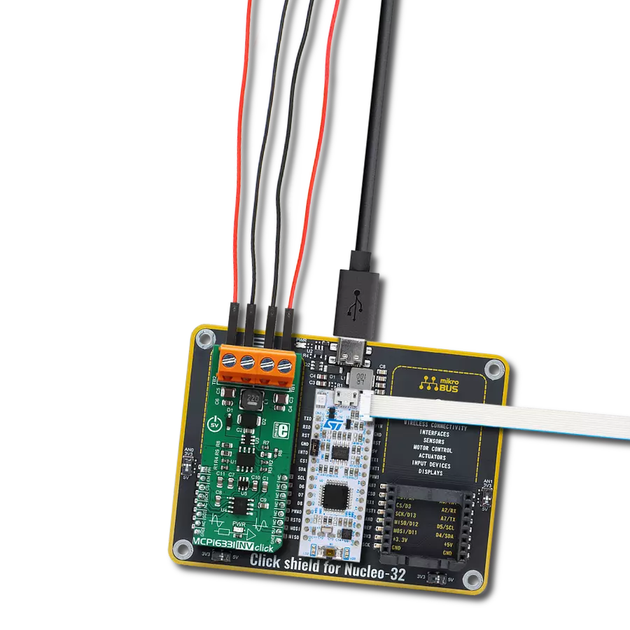
“仔细看看!”
Click board™ 原理图
一步一步来
项目组装

从选择您的开发板和Click板™开始。以Curiosity Nano with PIC18F57Q43作为您的开发板开始。


实时跟踪您的结果
应用程序输出
1. 应用程序输出 - 在调试模式下,“应用程序输出”窗口支持实时数据监控,直接提供执行结果的可视化。请按照提供的教程正确配置环境,以确保数据正确显示。

2. UART 终端 - 使用UART Terminal通过USB to UART converter监视数据传输,实现Click board™与开发系统之间的直接通信。请根据项目需求配置波特率和其他串行设置,以确保正常运行。有关分步设置说明,请参考提供的教程。

3. Plot 输出 - Plot功能提供了一种强大的方式来可视化实时传感器数据,使趋势分析、调试和多个数据点的对比变得更加直观。要正确设置,请按照提供的教程,其中包含使用Plot功能显示Click board™读数的分步示例。在代码中使用Plot功能时,请使用以下函数:plot(insert_graph_name, variable_name);。这是一个通用格式,用户需要将“insert_graph_name”替换为实际图表名称,并将“variable_name”替换为要显示的参数。

软件支持
库描述
该库包含 Buck & Boost Click 驱动程序的 API。
关键功能:
bucknboost_set_buck_out_voltage- 此功能设置所需降压通道的输出电压bucknboost_set_boost_out_voltage- 此功能设置升压通道 (CH6) 的输出电压bucknboost_get_status- 此功能读取电源良好、EEPROM 和过流状态寄存器
开源
代码示例
完整的应用程序代码和一个现成的项目可以通过NECTO Studio包管理器直接安装到NECTO Studio。 应用程序代码也可以在MIKROE的GitHub账户中找到。
/*!
 * @file main.c
 * @brief BucknBoost Click example
 *
 * # Description
 * This application demonstrates the use of Buck n Boost click board.
 *
 * The demo application is composed of two sections :
 *
 * ## Application Init
 * Initializes the driver and sets the click default configuration.
 * The default config enables the click board and limits the current of all outputs to 1100mA.
 * It also sets the default voltages of all channels which are the following:
 * OUT1 - 1.8V, OUT2 - 1.1V, OUT3 - 1.8V, OUT4 - 1.05V, OUT5 - 1.25V, OUT6 - 12V
 *
 * ## Application Task
 * Iterates through the entire range of Buck voltages for Buck 1 output starting from the maximal output.
 * It also checks the Power Good and Overcurrent status.
 * All data is being displayed on the USB UART where you can track the program flow.
 *
 * @author Stefan Filipovic
 *
 */

#include "board.h"
#include "log.h"
#include "bucknboost.h"

static bucknboost_t bucknboost;
static log_t logger;


void application_init ( void )
{
    log_cfg_t log_cfg;  /**< Logger config object. */
    bucknboost_cfg_t bucknboost_cfg;  /**< Click config object. */

    /**
     * Logger initialization.
     * Default baud rate: 115200
     * Default log level: LOG_LEVEL_DEBUG
     * @note If USB_UART_RX and USB_UART_TX
     * are defined as HAL_PIN_NC, you will
     * need to define them manually for log to work.
     * See @b LOG_MAP_USB_UART macro definition for detailed explanation.
     */
    LOG_MAP_USB_UART( log_cfg );
    log_init( &logger, &log_cfg );
    log_info( &logger, " Application Init " );

    // Click initialization.

    bucknboost_cfg_setup( &bucknboost_cfg );
    BUCKNBOOST_MAP_MIKROBUS( bucknboost_cfg, MIKROBUS_1 );

    err_t init_flag = bucknboost_init( &bucknboost, &bucknboost_cfg );
    if ( init_flag == I2C_MASTER_ERROR )
    {
        log_error( &logger, " Application Init Error. " );
        log_info( &logger, " Please, run program again... " );

        for ( ; ; );
    }

    init_flag = bucknboost_default_cfg ( &bucknboost );
    if ( init_flag == BUCKNBOOST_ERROR )
    {
        log_error( &logger, " Default Config Error. " );
        log_info( &logger, " Please, run program again... " );

        for ( ; ; );
    }

    log_info( &logger, " Application Task " );
}

void application_task ( void )
{
    bucknboost_status_t status_data;

    for ( uint8_t cnt = BUCKNBOOST_BUCK_OUTPUT_VOLTAGE_3300mV;
          cnt <= BUCKNBOOST_BUCK_OUTPUT_VOLTAGE_800mV; cnt++ )
    {
        err_t error_check = bucknboost_set_buck_out_voltage( &bucknboost,
                                                             BUCKNBOOST_OUTPUT_CH_1,
                                                             cnt );
        if ( error_check == BUCKNBOOST_ERROR )
        {
            log_error( &logger, " Setting Buck 1 Output Voltage." );
            Delay_ms ( 1000 );
            Delay_ms ( 1000 );
            Delay_ms ( 1000 );
        }
        else
        {
            log_printf( &logger, " Buck 1 Output Voltage set to %u mV.\r\n", 3300 - cnt * 50 );

            bucknboost_get_status( &bucknboost, &status_data );
            log_printf( &logger, " Power Good status -" );
            if ( status_data.power_good == BUCKNBOOST_PGOOD_ALL_MASK )
            {
                log_printf( &logger, " Valid!\r\n" );
            }
            else
            {
                log_printf( &logger, " Not Valid! - Mask: 0x%.2X\r\n", ( uint16_t ) status_data.power_good );
            }

            log_printf( &logger, " Overcurrent status -" );
            if ( status_data.power_good == BUCKNBOOST_PGOOD_ALL_MASK )
            {
                log_printf( &logger, " No Fault!\r\n" );
            }
            else
            {
                log_printf( &logger, " Fault! - Mask: 0x%.2X\r\n", ( uint16_t ) status_data.overcurrent_fault );
            }
            log_printf( &logger, "-----------------------------------\r\n" );
        }
        Delay_ms ( 1000 );
        Delay_ms ( 1000 );
    }
}

int main ( void )
{
    /* Do not remove this line or clock might not be set correctly. */
    #ifdef PREINIT_SUPPORTED
    preinit();
    #endif

    application_init( );

    for ( ; ; )
    {
        application_task( );
    }

    return 0;
}

// ------------------------------------------------------------------------ END