使用 CAV24C512 和 PIC18F57Q43 实现安全数据存储
高效的非易失性数据存储
已发布 6月 26, 2024
点击板
EEPROM 8 Click
开发板
Curiosity Nano with PIC18F57Q43
编译器
NECTO Studio
微控制器单元
PIC18F57Q43
将您的数据安全可靠地保存在硅中,长达一个世纪。
A
A
硬件概览
它是如何工作的?
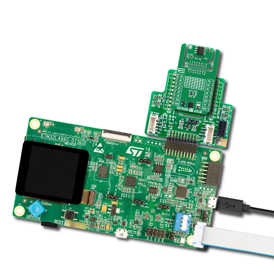
EEPROM 8 Click基于ON Semiconductor的CAV24C512,这是一款512Kb EEPROM,具有I2C接口和写保护模式。CAV24C512被组织为65,536个8位字,并且由于其广泛的电源供应范围和100年的数据保留时间,将其空前的数据存储与优秀的能源效率相结合。它非常可靠,可持续进行一百万次的全内存读/写/擦除循环。芯片内置的错误校正码(ECC)使得此Click board™非常适用于可靠性要
求高、可靠的非易失性存储器存储是必不可少的高可靠性应用。此Click board™使用标准的I2C 2-Wire接口与MCU通信,支持标准(100 kHz)、快速(400 kHz)和快速加速(1MHz)工作模式。CAV24C512具有7位从设备地址,前五位MSB固定为1010。地址引脚A0、A1和A2由用户进行编程,并确定从设备地址的最后三位LSB的值,可以通过将标记为ADDR SEL的板载SMD跳线置于标记为0或1
的适当位置来选择。此外,可配置的写保护功能,mikroBUS™插座上的WP引脚,允许用户冻结整个存储区域,从而保护免受写指令的干扰。此Click board™可以通过VCC SEL跳线选择使用3.3V或5V逻辑电压电平运行。这样,既能支持3.3V,又能支持5V的MCU可以正确使用通信线。然而,此Click board™配备了一个包含易于使用的函数和示例代码的库,可作为进一步开发的参考。


功能概述
开发板
PIC18F57Q43 Curiosity Nano 评估套件是一款尖端的硬件平台,旨在评估 PIC18-Q43 系列内的微控制器。其设计的核心是包含了功能强大的 PIC18F57Q43 微控制器(MCU),提供先进的功能和稳健的性能。这个评估套件的关键特点包括一个黄 色用户 LED 和一个响应灵敏的机械用户开关,提供无
缝的交互和测试。为一个 32.768kHz 水晶振荡器足迹提供支持,确保精准的定时能力。套件内置的调试器拥有一个绿色电源和状态 LED,使编程和调试变得直观高效。此外,增强其实用性的还有虚拟串行端口 (CDC)和一个调试 GPIO 通道(DGI GPIO),提供广泛的连接选项。该套件通过 USB 供电,拥有由
MIC5353 LDO 调节器提供支持的可调目标电压功能,确保在 1.8V 至 5.1V 的输出电压范围内稳定运行,最大输出电流为 500mA,受环境温度和电压限制。

微控制器概述
MCU卡片 / MCU

建筑
PIC
MCU 内存 (KB)
128
硅供应商
Microchip
引脚数
48
RAM (字节)
8196
你完善了我!
配件
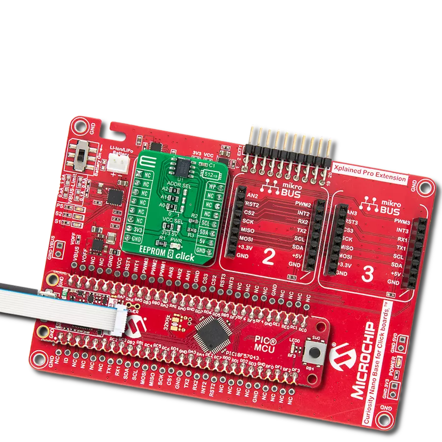
Curiosity Nano Base for Click boards 是一款多功能硬件扩展平台,专为简化 Curiosity Nano 套件与扩展板之间的集成而设计,特别针对符合 mikroBUS™ 标准的 Click 板和 Xplained Pro 扩展板。这款创新的基板(屏蔽板)提供了无缝的连接和扩展可能性,简化了实验和开发过程。主要特点包括从 Curiosity Nano 套件提供 USB 电源兼容性,以及为增强灵活性而提供的另一种外部电源输入选项。板载锂离子/锂聚合物充电器和管理电路确保电池供电应用的平稳运行,简化了使用和管理。此外,基板内置了一个固定的 3.3V 电源供应单元,专用于目标和 mikroBUS™ 电源轨,以及一个固定的 5.0V 升压转换器,专供 mikroBUS™ 插座的 5V 电源轨,为各种连接设备提供稳定的电力供应。

使用的MCU引脚
mikroBUS™映射器
“仔细看看!”
Click board™ 原理图

一步一步来
项目组装

从选择您的开发板和Click板™开始。以Curiosity Nano with PIC18F57Q43作为您的开发板开始。


实时跟踪您的结果
应用程序输出
1. 应用程序输出 - 在调试模式下,“应用程序输出”窗口支持实时数据监控,直接提供执行结果的可视化。请按照提供的教程正确配置环境,以确保数据正确显示。

2. UART 终端 - 使用UART Terminal通过USB to UART converter监视数据传输,实现Click board™与开发系统之间的直接通信。请根据项目需求配置波特率和其他串行设置,以确保正常运行。有关分步设置说明,请参考提供的教程。

3. Plot 输出 - Plot功能提供了一种强大的方式来可视化实时传感器数据,使趋势分析、调试和多个数据点的对比变得更加直观。要正确设置,请按照提供的教程,其中包含使用Plot功能显示Click board™读数的分步示例。在代码中使用Plot功能时,请使用以下函数:plot(insert_graph_name, variable_name);。这是一个通用格式,用户需要将“insert_graph_name”替换为实际图表名称,并将“variable_name”替换为要显示的参数。

软件支持
库描述
该库包含 EEPROM 8 Click 驱动程序的 API。
关键功能:
eeprom8_write_page- 此函数从所选寄存器开始写入最多128字节的数据。eeprom8_read_random_byte- 此函数从所选寄存器读取一个字节的数据。eeprom8_read_sequential- 此函数从所选寄存器开始读取所需数量的字节。
开源
代码示例
完整的应用程序代码和一个现成的项目可以通过NECTO Studio包管理器直接安装到NECTO Studio。 应用程序代码也可以在MIKROE的GitHub账户中找到。
/*!
 * @file main.c
 * @brief EEPROM8 Click example
 *
 * # Description
 * This example demonstrates the use of EEPROM 8 Click board by writing specified data to
 * the memory and reading it back.
 *
 * The demo application is composed of two sections :
 *
 * ## Application Init
 * Initializes the driver and USB UART logging.
 *
 * ## Application Task
 * Task writes a desired number of data bytes to the EEPROM 8 memory
 * and verifies that it is written correctly by reading from the same memory location and
 * in case of successful read, displays the memory content on the USB UART.
 * This is done in two passes.
 *
 * @author Stefan Popovic
 *
 */

#include "board.h"
#include "log.h"
#include "eeprom8.h"

static eeprom8_t eeprom8;
static log_t logger;

// Number of test bytes
#define TEST_NBYTES ( 150 )

// Starting address for example
#define TEST_MEM_LOCATION ( EEPROM8_BLOCK_ADDR_START + 1024ul )

static uint8_t  cnt = 0;
static uint8_t  test_write_buffer[ TEST_NBYTES ]  = { 0 };
static uint8_t  test_read_buffer[ TEST_NBYTES ]   = { 0 };
static uint16_t addr_offset = TEST_MEM_LOCATION;

/**
 * @brief First pass function
 * @details This function writes and reads defined number of bytes
 *  with zero values
 * @param[in] ctx  Click object.
 * @param[in] write_buf  Data to be written.
 * @param[out] read_buf  Data to be read.
 * @return @li @c  0 - Success,
 *         @li @c -1 - Error.
 * See #err_t definition for detailed explanation.
 * @note None.
 */
err_t run_first_pass( eeprom8_t* ctx, uint8_t* write_buf, uint8_t* read_buf );

/**
 * @brief Second pass function
 * @details This function writes and reads defined number of bytes
 *  with the values following arithmetical progression
 * @param[in] ctx  Click object.
 * @param[in] write_buf  Data to be written.
 * @param[out] read_buf  Data to be read.
 * @return @li @c  0 - Success,
 *         @li @c -1 - Error.
 * See #err_t definition for detailed explanation.
 * @note None.
 */
err_t run_second_pass( eeprom8_t* ctx, uint8_t* write_buf, uint8_t* read_buf );

void application_init ( void )
{
    eeprom8_cfg_t eeprom8_cfg;  /**< Click config object. */
    log_cfg_t log_cfg;          /**< Logger config object. */

    /**
     * Logger initialization.
     * Default baud rate: 115200
     * Default log level: LOG_LEVEL_DEBUG
     * @note If USB_UART_RX and USB_UART_TX
     * are defined as HAL_PIN_NC, you will
     * need to define them manually for log to work.
     * See @b LOG_MAP_USB_UART macro definition for detailed explanation.
     */
    LOG_MAP_USB_UART( log_cfg );
    log_init( &logger, &log_cfg );
    log_info( &logger, " Application Init " );

    //  Click initialization.
    eeprom8_cfg_setup( &eeprom8_cfg );
    EEPROM8_MAP_MIKROBUS( eeprom8_cfg, MIKROBUS_1 );
    if ( I2C_MASTER_ERROR == eeprom8_init( &eeprom8, &eeprom8_cfg ) )
    {
        log_error( &logger, " Communication Init " );
        for ( ; ; );
    }

    log_info( &logger, " Application Task " );
}

void application_task ( void )
{
    // Reset variables
    cnt = 0;
    memset( test_read_buffer, 0, sizeof ( test_read_buffer ) );
    addr_offset = TEST_MEM_LOCATION;

    // Initiate first pass
    //  filling the eeprom addresses with zeros
    if( EEPROM8_ERROR == run_first_pass( &eeprom8, test_write_buffer, test_read_buffer ) )
    {
        log_error( &logger, " First Pass Failed " );
    }

    // Initiate second pass
    //  filling the eeprom addresses with values following arithmetic sequence with difference of 1
    if( EEPROM8_ERROR == run_second_pass( &eeprom8, test_write_buffer, test_read_buffer ) )
    {
        log_error( &logger, " Second Pass Failed " );
    }

    log_printf( &logger, " \r\nInitiating new iteration\r\n " );
    // 6 seconds delay
    Delay_ms ( 1000 );
    Delay_ms ( 1000 );
    Delay_ms ( 1000 );
    Delay_ms ( 1000 );
    Delay_ms ( 1000 );
    Delay_ms ( 1000 );
}

int main ( void )
{
    /* Do not remove this line or clock might not be set correctly. */
    #ifdef PREINIT_SUPPORTED
    preinit();
    #endif

    application_init( );

    for ( ; ; )
    {
        application_task( );
    }

    return 0;
}

// First pass: writing zero values into eeprom memory and reading them back
err_t run_first_pass( eeprom8_t* ctx, uint8_t* write_buf, uint8_t* read_buf )
{
    // Fill write buffer with zeros
    memset( write_buf, 0, TEST_NBYTES );

    // Fill whole page with zeros using page write operation
    eeprom8_write_enable( ctx );
    if ( EEPROM8_ERROR == eeprom8_write_page( ctx, addr_offset, write_buf ) )
    {
        log_error( &logger, " Write Page Failed " );
        return EEPROM8_ERROR;
    }
    cnt += EEPROM8_NBYTES_PAGE;

    // Fill remaining adresses with zero using byte write operation
    addr_offset += EEPROM8_NBYTES_PAGE;

    while( cnt < TEST_NBYTES )
    {
        if ( EEPROM8_ERROR == eeprom8_write_byte( ctx, addr_offset++, 0 ) )
        {
            log_error( &logger, " Write %d. Byte Failed ", ( uint16_t ) cnt );
            return EEPROM8_ERROR;
        }
        cnt++;
        Delay_10ms( );
    }
    eeprom8_write_protect( ctx );

    Delay_1sec( );

    // Read defined number of bytes starting from the test memory location
    addr_offset = TEST_MEM_LOCATION;
    if ( EEPROM8_ERROR == eeprom8_read_sequential( ctx, addr_offset, TEST_NBYTES, read_buf ) )
    {
         log_error( &logger, "Read Sequential Failed" );
         return EEPROM8_ERROR;
    }

    // compare written and read buffers and log data in case of a match
    if ( memcmp( write_buf, read_buf, sizeof( write_buf ) ) == 0 )
    {
        log_printf( &logger,
                    " \r\nFirst pass: reading %d bytes data starting from eeprom address 0x%x\r\n ",
                    ( uint16_t ) TEST_NBYTES,
                    ( uint32_t ) TEST_MEM_LOCATION );
        for ( cnt = 0; cnt < TEST_NBYTES; cnt++ )
        {
            log_printf( &logger, " %d", ( uint16_t ) read_buf[ cnt ] );
            Delay_ms ( 50 );
        }

        log_printf( &logger, "\r\n\r\n" );
    }
    else
    {
        return EEPROM8_ERROR;
    }
    return EEPROM8_OK;
}

// Second pass: writing incremental values into eeprom memory and reading them back
err_t run_second_pass( eeprom8_t* ctx, uint8_t* write_buf, uint8_t* read_buf )
{
    for ( cnt = 0; cnt < TEST_NBYTES; cnt++ )
    {
        write_buf[ cnt ] = cnt + 1;
    }
    // Write buffer data using page write operation
    cnt = 0;
    eeprom8_write_enable( ctx );
    if ( EEPROM8_ERROR == eeprom8_write_page( ctx, addr_offset, write_buf ) )
    {
        log_error( &logger, " Write Page Failed ");
        return EEPROM8_ERROR;
    }
    cnt += EEPROM8_NBYTES_PAGE;

    // Write remaining buffer data using byte write operation
    addr_offset += EEPROM8_NBYTES_PAGE;

    while ( cnt < TEST_NBYTES )
    {
        if ( EEPROM8_ERROR == eeprom8_write_byte( ctx, addr_offset++, write_buf[ cnt++ ] ) )
        {
            log_error( &logger, " Write %d. Byte Failed ", ( uint16_t ) cnt );
            return EEPROM8_ERROR;
        }
        Delay_10ms( );
    }
    eeprom8_write_protect( ctx );

    Delay_ms ( 1000 );

    // Read bytes of the page size starting from the test memory location
    addr_offset = TEST_MEM_LOCATION;
    if ( EEPROM8_ERROR == eeprom8_read_sequential( ctx, addr_offset, EEPROM8_NBYTES_PAGE, read_buf ) )
    {
        log_error( &logger, " Read Sequential Failed " );
        return EEPROM8_ERROR;
    }

    // Read two bytes with random byte read operation
    addr_offset += EEPROM8_NBYTES_PAGE;
    cnt = EEPROM8_NBYTES_PAGE;

    if( EEPROM8_ERROR == eeprom8_read_random_byte( ctx, addr_offset, &read_buf[ cnt++ ] ) )
    {
        log_error( &logger, " Read %d. Random Byte Failed ", ( uint16_t ) cnt-1 );
        return EEPROM8_ERROR;
    }
    ++addr_offset;
    if( EEPROM8_ERROR == eeprom8_read_random_byte( ctx, addr_offset, &read_buf[ cnt++ ] ) )
    {
        log_error( &logger, " Read %d. Random Byte Failed ", ( uint16_t ) cnt-1 );
        return EEPROM8_ERROR;
    }

    // Read the rest of the bytes with current address read operation
    while ( cnt < TEST_NBYTES )
    {
        if( EEPROM8_ERROR == eeprom8_read_current_byte( ctx, &read_buf[ cnt++ ] ) )
        {
            log_error( &logger, " Read %d. Current Byte Failed ", ( uint16_t ) cnt-1 );
            return EEPROM8_ERROR;
        }
    }
    // compare written and read buffers and log data in case of a match
    if ( memcmp( write_buf, read_buf, TEST_NBYTES ) == 0 )
    {
        log_printf( &logger,
                    " \r\nSecond pass: reading %d bytes data starting from eeprom address 0x%x\r\n ",
                    ( uint16_t ) TEST_NBYTES,
                    ( uint32_t ) TEST_MEM_LOCATION );
        for ( cnt = 0; cnt < TEST_NBYTES; cnt++ )
        {
            log_printf( &logger, " %d", ( uint16_t )read_buf[ cnt ] );
            Delay_ms ( 50 );
        }

        log_printf( &logger, "\r\n\r\n" );
    }
    else
    {
        return EEPROM8_ERROR;
    }
    return EEPROM8_OK;
}

// ------------------------------------------------------------------------ END
额外支持
资源
类别:电可擦只读存储器