使用DS2413和ATmega328变革您的硬件管理
告别复杂的设备控制

已发布 6月 24, 2024
点击板
1-Wire Switch Click
开发板
Arduino UNO Rev3
编译器
NECTO Studio
微控制器单元
ATmega328
使用可编程 I/O 1-Wire 开关,将您的设备控制提升到一个新的水平 - 这是一种轻松实现远程切换和感知设备的方法。
A
A
硬件概览
它是如何工作的?
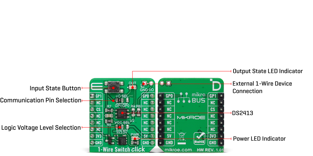
1-Wire Switch Click 基于 Analog Devices 的 DS2413,这是一款双通道可寻址开关。DS2413 将两个可编程 I/O 引脚和一个完全功能的 1-Wire 接口集成在一个封装中,确保 PIO 输出更改无误。PIO 输出配置为开漏,工作电压高达 28V(在最终应用中提供高水平的容错能力),最大导通电阻为 20Ω。通过监测其可编程 I/O 引脚的电压,DS2413 允许您读取负载的状态,在这种配置中,这个按钮的状态作为输入,而输出状态通过标记为 OUT 的红色 LED 进行视觉检测。DS2413 的电源通
过 1-Wire 总线寄生供电,1-Wire 总线系统具有一个总线控制器和一个或多个外围设备。考虑到这一点,此 Click board™ 具有一个额外的未填充头,可以连接其他外部 1-Wire 设备,从而在一个控制器上形成一条具有多个外围设备的线。DS2413 还具有 64 位长的注册号,保证唯一识别。在多路复用 1-Wire 网络环境中,该编号用于寻址设备,其中多个设备位于公共 1-Wire 总线上并独立操作。如前所述,1-Wire Switch Click 使用 1-Wire 接口与 MCU 通信,根据定义,该接口只需一条数据
线(和地线)即可与 MCU 通信。1-Wire 通信线被路由到标记为 I/O SEL 的 SMD 跳线,允许将 1-Wire 通信路由到 mikroBUS™ 插座的 GP0 引脚或 GP1 引脚。这些引脚分别标记为与 SMD 跳线位置相同,使所需引脚的选择简单明了。此 Click board™ 可以在 3.3V 或 5V 逻辑电压水平下运行,通过 VCC SEL 跳线选择。这样,3.3V 和 5V 的 MCU 都可以正确使用通信线路。此外,该 Click board™ 配备了包含易于使用的函数和示例代码的库,可作为进一步开发的参考。
功能概述
开发板
Arduino UNO 是围绕 ATmega328P 芯片构建的多功能微控制器板。它为各种项目提供了广泛的连接选项,具有 14 个数字输入/输出引脚,其中六个支持 PWM 输出,以及六个模拟输入。其核心组件包括一个 16MHz 的陶瓷谐振器、一个 USB 连接器、一个电
源插孔、一个 ICSP 头和一个复位按钮,提供了为板 子供电和编程所需的一切。UNO 可以通过 USB 连接到计算机,也可以通过 AC-to-DC 适配器或电池供电。作为第一个 USB Arduino 板,它成为 Arduino 平台的基准,"Uno" 符号化其作为系列首款产品的地
位。这个名称选择,意为意大利语中的 "一",是为了 纪念 Arduino Software(IDE)1.0 的推出。最初与 Arduino Software(IDE)版本1.0 同时推出,Uno 自此成为后续 Arduino 发布的基础模型,体现了该平台的演进。

微控制器概述
MCU卡片 / MCU

建筑
AVR
MCU 内存 (KB)
32
硅供应商
Microchip
引脚数
32
RAM (字节)
2048
你完善了我!
配件
Click Shield for Arduino UNO 具有两个专有的 mikroBUS™ 插座,使所有 Click board™ 设备能够轻松与 Arduino UNO 板进行接口连接。Arduino UNO 是一款基于 ATmega328P 的微控制器开发板,为用户提供了一种经济实惠且灵活的方式来测试新概念并构建基于 ATmega328P 微控制器的原型系统,结合了性能、功耗和功能的多种配置选择。Arduino UNO 具有 14 个数字输入/输出引脚(其中 6 个可用作 PWM 输出)、6 个模拟输入、16 MHz 陶瓷谐振器(CSTCE16M0V53-R0)、USB 接口、电源插座、ICSP 头和复位按钮。大多数 ATmega328P 微控制器的引脚都连接到开发板左右两侧的 IO 引脚,然后再连接到两个 mikroBUS™ 插座。这款 Click Shield 还配备了多个开关,可执行各种功能,例如选择 mikroBUS™ 插座上模拟信号的逻辑电平,以及选择 mikroBUS™ 插座本身的逻辑电压电平。此外,用户还可以通过现有的双向电平转换电压转换器使用任何 Click board™,无论 Click board™ 运行在 3.3V 还是 5V 逻辑电压电平。一旦将 Arduino UNO 板与 Click Shield for Arduino UNO 连接,用户即可访问数百种 Click board™,并兼容 3.3V 或 5V 逻辑电压电平的设备。

使用的MCU引脚
mikroBUS™映射器
“仔细看看!”
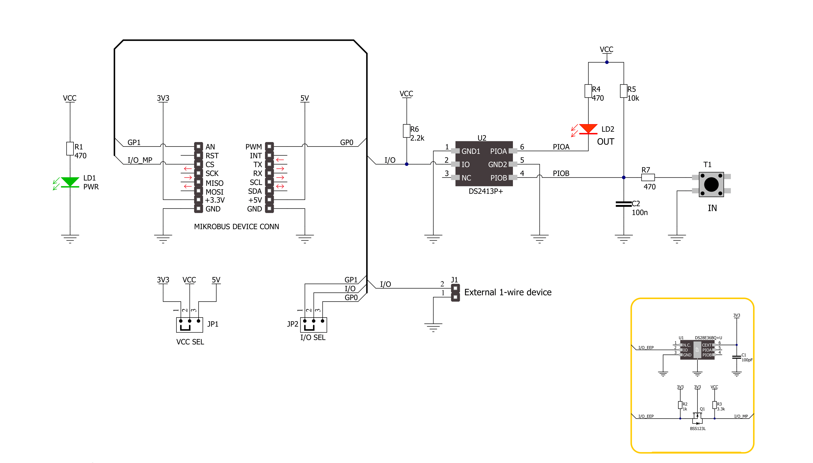
Click board™ 原理图
一步一步来
项目组装

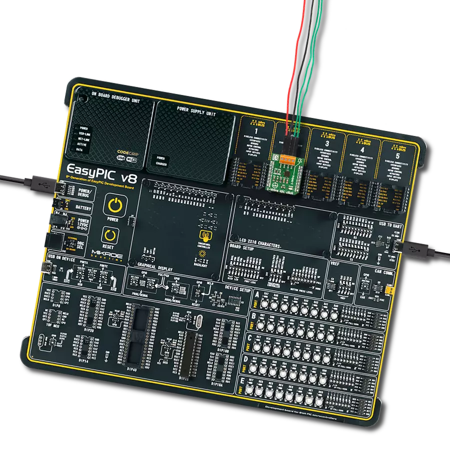
从选择您的开发板和Click板™开始。以Arduino UNO Rev3作为您的开发板开始。


软件支持
库描述
该库包含 1-Wire Switch Click 驱动程序的 API。
关键功能:
c1wireswitch_set_pio_state- 1-Wire Switch 写入特定可编程 I/O 状态功能c1wireswitch_get_pio_state- 1-Wire Switch 读取特定可编程 I/O 状态功能c1wireswitch_get_pio_latch_state- 1-Wire Switch 读取可编程 I/O 锁存状态功能
开源
代码示例
完整的应用程序代码和一个现成的项目可以通过NECTO Studio包管理器直接安装到NECTO Studio。 应用程序代码也可以在MIKROE的GitHub账户中找到。
/*!
 * @file main.c
 * @brief 1-Wire Switch Click Example.
 *
 * # Description
 * This library contains API for 1-Wire Switch Click driver.
 * The library initializes and defines the 1-Wire bus drivers to
 * write and read data for state programmable I/O,
 * as well as the default configuration.
 *
 * The demo application is composed of two sections :
 *
 * ## Application Init
 * Initializes the driver and performs default configuration and sets
 * the PIO A to OFF and PIO B to ON state.
 *
 * ## Application Task
 * This example demonstrates the use of the 1-Wire Switch Click board by changing the PIO A state,
 * which is controlling the LED, every time the state of PIO B changes.
 * Change on the PIO B happens when the button is pushed.
 *
 * @author Stefan Ilic
 *
 */

#include "board.h"
#include "log.h"
#include "c1wireswitch.h"

static c1wireswitch_t c1wireswitch;
static log_t logger;
static uint8_t state = 0;

void application_init ( void )
{
    log_cfg_t log_cfg;  /**< Logger config object. */
    c1wireswitch_cfg_t c1wireswitch_cfg;  /**< Click config object. */

    /**
     * Logger initialization.
     * Default baud rate: 115200
     * Default log level: LOG_LEVEL_DEBUG
     * @note If USB_UART_RX and USB_UART_TX
     * are defined as HAL_PIN_NC, you will
     * need to define them manually for log to work.
     * See @b LOG_MAP_USB_UART macro definition for detailed explanation.
     */
    LOG_MAP_USB_UART( log_cfg );
    log_init( &logger, &log_cfg );
    log_info( &logger, " Application Init " );

    // Click initialization.
    c1wireswitch_cfg_setup( &c1wireswitch_cfg );
    C1WIRESWITCH_MAP_MIKROBUS( c1wireswitch_cfg, MIKROBUS_1 );
    if ( ONE_WIRE_ERROR == c1wireswitch_init( &c1wireswitch, &c1wireswitch_cfg ) )
    {
        log_error( &logger, " Communication init." );
        for ( ; ; );
    }

    if ( C1WIRESWITCH_ERROR == c1wireswitch_default_cfg ( &c1wireswitch ) )
    {
        log_error( &logger, " Default configuration." );
        for ( ; ; );
    }

    c1wireswitch_set_pio_state( &c1wireswitch, C1WIRESWITCH_PIOA_OFF, C1WIRESWITCH_PIOB_ON );

    log_info( &logger, " Application Task " );
}

void application_task ( void )
{
    uint8_t pio_a = 0;
    uint8_t pio_b = 0;

    c1wireswitch_get_pio_state( &c1wireswitch, &pio_a, &pio_b );

    if ( pio_b == C1WIRESWITCH_PIOB_OFF )
    {
        if ( state == 0 )
        {
            c1wireswitch_set_pio_state( &c1wireswitch, C1WIRESWITCH_PIOA_ON, C1WIRESWITCH_PIOB_ON );
            log_printf( &logger, " Button is pressed, LED is ON. \r\n " );
            state = 1;
        }
        else
        {
            c1wireswitch_set_pio_state( &c1wireswitch, C1WIRESWITCH_PIOA_OFF, C1WIRESWITCH_PIOB_ON );
            log_printf( &logger, " Button is pressed, LED is OFF. \r\n " );
            state = 0;
        }
        Delay_ms ( 100 );
    }
    Delay_ms ( 100 );
}

int main ( void )
{
    /* Do not remove this line or clock might not be set correctly. */
    #ifdef PREINIT_SUPPORTED
    preinit();
    #endif

    application_init( );

    for ( ; ; )
    {
        application_task( );
    }

    return 0;
}

// ------------------------------------------------------------------------ END
额外支持
资源
类别:单线